Table of Contents
Advertisement
Advertisement
Table of Contents

Subscribe to Our Youtube Channel
Summary of Contents for Lippert Components Tire Linc 2.0
- Page 1 Tire Linc Tyre Pressure ® & Temperature Monitoring System 2.0 OWNER'S MANUAL (AU)
-
Page 2: Table Of Contents
TABLE OF CONTENTS Introduction Key System Components Safety Pairing OneControl BT App to Repeater Preparation Install Repeater Stem Sensor Pairing Sequence Pair Stem Sensors to Repeater Via Smart Phone Operation Tyre Limits Example Configure All Sensors Troubleshooting Remove Stem Sensor to Change Battery Factory Reset No Power Learn Sensors Procedure Resets System... - Page 3 The "WARNING" symbol above is a sign that a procedure has a safety risk involved and may cause death, serious personal injury, severe product and/or property damage if not performed safely and within the parameters set forth in this manual. Failure to follow instructions provided in this manual may result in death, serious personal injury and/or severe product and property damage, including voiding of the component warranty.
-
Page 4: Pairing Onecontrol Bt App To Repeater
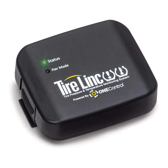
Preparation Install Repeater Locate and remove film cover (Fig. 2A) from repeater dock. NOTE: Film cover should be removed only when ready to install repeater. Snap the repeater (Fig. 2B) into the repeater dock (Fig. 2C). NOTE: The repeater dock is keyed and the repeater can only be installed in one way. The repeater will power on, lighting up the Status LED (Fig. - Page 5 OneControl BT requires location permission to find and connect to available networks (Fig. 5). Tap Continue button to proceed with setup. Allow OneControl BT access to the device's location (Fig. 6). Make a selection to move forward with setup. Tapping the Deny button will stop the process. Look for Tire Linc and tap the listing.
- Page 6 The screen will indicate the RV has connected successfully (Fig. 8). Tap Continue button to proceed. Tap the SETUP COACH button to continue (Fig. 9A). Fig. 8 Fig. 9 10. Select a vehicle class and tap CONTINUE (Fig. 10). 11. Select a vehicle layout and tap FINISH (Fig. 11). 12.
-
Page 7: Stem Sensor Pairing Sequence
Stem Sensor Pairing Sequence The pairing sequence for Stem Sensors (Fig. 13) is as follows: SINGLE AXLE: Stem Sensors for a single-axle caravan MUST be paired in the following order: Left Front (Fig.14A) and Right Front (Fig.14C). DOUBLE AXLE: Stem Sensors for a double-axle caravan MUST be paired in the following order: Left Front (Fig.14A), Left Rear (Fig.14B), Right Front (Fig.14C) and Right Rear (Fig.14D). -
Page 8: Pair Stem Sensors To Repeater Via Smart Phone
Pair Stem Sensors to Repeater Via Smart Phone NOTE: If a wrong caravan type is chosen or there is a new caravan configuration, see Troubleshooting section for factory reset. The OneControl BT app on the smart phone will indicate in specific order which tyre the stem sensor cap should be installed on: Front Left, Rear Left, Front Right, Rear Right, etc. -
Page 9: Operation
D. After the sensor has been found, the app will indicate the next stem sensor to be paired (Fig.17B). Repeat step 2B, 2C and 2D until all sensors are learned (Fig.18). Tap the FINISHED button (Fig.18A) to exit TYRE PRESSURE Sensor Configuration mode. Tapping FINISHED exits configuration mode and redisplays the Tyre Pressure screen (Fig. - Page 10 B. The app will automatically detect the Tire Linc system. NOTE: If necessary, follow the online prompts to set up Tire Linc within the OneControl BT app. The smart phone will connect to the repeater and the app will display a caravan image with tyre pressures and temperatures.
-
Page 11: Tyre Limits Example
Tyre Limits Example Programmable tyre limits have a “next” arrow (>) that, when tapped, opens that feature’s scrollable window of available settings. Scroll through the limits window to find the desired setting, select it, then tap the “back” arrow (<) located above the tyre’s name at the top of the window’s heading. The following example illustrates the interaction between the various tyre settings and how the resulting information is relayed by the monitoring system for display in the app. - Page 12 The Maximum Temperature (Fig. 22A) and the Maximum Temp Change (Fig. 22B) can also be adjusted in similar fashion. Locate the current settings (Figs. 25 and 26) and modify as needed. NOTE: Stem Sensor Temperature Reading Tolerance: +/-3 °C (+/-5.4 °F). For example, if a Stem Sensor reports tyre temperature at 29 °C (85 °F), actual tyre temperature may be 32–26 °C (90.4–79.6 °F).
-
Page 13: Configure All Sensors
Configure All Sensors As an option to configuring sensors individually, all the sensors can be configured simultaneously. Tap the arrow by Configure All Sensors (Fig. 27A). The next screen features settings for all programmable limits (Fig. 28). Select the arrow to the right of the setting to establish pressure and temperature limits for all the sensors. -
Page 14: Troubleshooting
Troubleshooting Remove Stem Sensor to Change Battery Removal of the Stem Sensor battery can be completed with the included Stem Sensor tool. The Stem Sensor tool, which is taken apart to utilize, is comprised of two pieces molded to match the tops and bottoms of the Stem Sensors. -
Page 15: Notes
Notes Page 15 Rev: 09.27.21 CCD-0004071... - Page 16 The contents of this manual are proprietary and copyright protected by Lippert Components, Inc. (LCI). LCI prohibits the copying or dissemination of portions of this manual unless prior written consent from an authorized LCI representative has been provided. Any unauthorized use shall void any applicable warranty. ...


Need help?
Do you have a question about the Tire Linc 2.0 and is the answer not in the manual?
Questions and answers