Table of Contents
Advertisement
Quick Links
IL-2000SA
SERVICE MANUAL
First Edition, November 2007
Manual No. RS-61021-11
CAUTION
READ AND UNDERSTAND THIS MANUAL
• Thoroughly read and understand this manual before installing, operating, inspecting, or
servicing the machine.
• Keep this manual in a safe place where you can refer to it whenever necessary.
107743
Advertisement
Table of Contents

Summary of Contents for ISHIDA IL-2000SA
- Page 1 IL-2000SA SERVICE MANUAL First Edition, November 2007 Manual No. RS-61021-11 CAUTION READ AND UNDERSTAND THIS MANUAL • Thoroughly read and understand this manual before installing, operating, inspecting, or servicing the machine. • Keep this manual in a safe place where you can refer to it whenever necessary.
- Page 2 © 2007 ISHIDA Co., Ltd. COPYRIGHT AND COPY PERMISSION This manual shall not be copied without permission. This manual is protected by copyright and is intended solely for use in conjunction with the machine. Please notify us before copying or reproducing this manual in any manner, for any other purpose.
- Page 3 ISHIDA is not liable for any damage, loss or injury that results from incorrect handling, insufficient caution, unauthorized modifications to the machine, or failure to follow the instructions contained in this manual.
- Page 4 Additionally, there may be significant property damage Indicates a potentially hazardous situation where, if not avoided, may result in minor or moderate injury or in property damage. Indicates a reminder or emphasis of information. IL-2000SA User’s Manual...
-
Page 5: Table Of Contents
Chapter 4 SYSTEM SETTING MENU ..........4-1 START UP OF SYSTEM SETTING MENU ..........4-1 HIERARCHICAL CHART OF SYSTEM SETTING MENU ...... 4-2 SALES MODE SETTING................. 4-3 MACHINE NUMBER SETTING ............... 4-4 HOLD DATA SETTING ................4-5 IL-2000SA Service Manual... - Page 6 Chapter 6 HARDWARE CONFIGURATION ........6-1 MECHANICAL COMPONENTS .............. 6-1 1. Main Unit ...................... 6-1 2. Printer Unit ....................6-2 3. Display Unit ....................6-3 ELECTRICITY ..................6-4 1. Electric Block ....................6-4 2. Board Setting ....................6-5 IL-2000SA Service Manual...
-
Page 7: Chapter 1 Outline
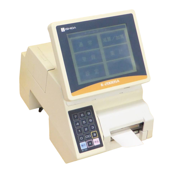
OUTLINE CHAPTER OUTLINE OUTLINE The IL-2000SA is a label printer that has the same functions as the SR-2000α except for the weighing unit. The main board, printer board, and cassette of the IL-2000SA are common to the SR-2000α. SPECIFICATIONS Items... -
Page 8: Feature
(6) The mechanism is simplified by adopting the prism for the label sensor (transparent type), and the machine height can be lowered. (7) The micro step drive is adopted for the label feeding motor, therefore, smoother rotation becomes possible. IL-2000SA (micro step drive) (8) Modular connector is adopted for the I NET communication. L-2000SA (modular) - Page 9 Chapter 1 OUTLINE (9) The RS-232C port for general-purpose interlock is installed. IL-2000SA (RS-232C port) (10) The card slot (PCMCIA) port is provided. IL-2000SA (PCMCIA port) (11) CompactFlash/flash ROM is adopted for the program storage. IL-2000SA (CompactFlash) CompactFlash (32 Mbyte) ....OS + Application program Flash ROM (1 Mbyte) ......
-
Page 11: Chapter 2 Installation
Chapter 2 INSTALLATION CHAPTER INSTALLATION 2.1 OUTER DIMENSIONS Power supply cable (1.8m) IL-2000SA Service Manual... -
Page 12: Contents Of The Package
Check that the following items are included in a package. (1) IL-2000SA (2) User’s manual (3) Head cleaning sheet (sheet wrapping film 68-5054-09) (4) Cleaning pen 1. Items Required at the Delivery (1) C/F card (2) C/F card adapter IL-2000SA Service Manual... -
Page 13: Installation
Make sure to use an appropriate power supply. Power supply with noise or voltage drop may cause malfunction. Use a dedicated power supply. Example To avoid electric shock, make sure to connect the ground wire (at least third class grounding). IL-2000SA Service Manual... -
Page 14: Setup
(19) Refer to the User’s Manual to register the necessary items. (20) Check the operation. (Perform production with user data.) 3. Handling Description Give operating and handling instructions of the machine to users and check that the instructions are fully understood. IL-2000SA Service Manual... -
Page 15: Chapter 3 Test Mode
How to advance each item Press the touch key of the item to be selected on the screen. How to return to the previous menu Touch the [MENU] key to return the display to the previous menu screen. IL-2000SA Service Manual... -
Page 16: Test Mode Hierarchical Chart
Chapter 3 TEST MODE TEST MODE HIERARCHICAL CHART The modes (All-diagnostic and Time/Date setting) described in the dotted line are only for the product check in the factory. IL-2000SA Service Manual... -
Page 17: Key Check
1. Numeric Key Check Operation Press each numeric key, then the corresponding screen key displays in reverse. The left screen is an example when [8] key is pressed. After a while, the reversed key on the screen is cleared. IL-2000SA Service Manual... -
Page 18: Touch Panel Adjustment
Coordinates of the inputted touch panel are displayed at the bottom left corner of the screen. If the screen key position misalignment occurs, perform the following key operation on the operating console while in the Main Menu to enter this mode. IL-2000SA Service Manual... -
Page 19: All Diagnosis
(1) Defect of P-910 Communication check NET loopback hardware check (1) Defect of P-910 (ELAN→ILAN) * The check cable is required. Communication check NET loopback hardware check (1) Defect of P-910 (ILAN→ELAN) * The check cable is required. IL-2000SA Service Manual... -
Page 20: Memory Clear
All masters are cleared except the system master. System Data Initialization The system master is returned to the initial values, and the system data is set to the initial values. Test Data Setting The master for test is set. IL-2000SA Service Manual... -
Page 21: Display Check
Horizontal/Vertical Perform a visual check to confirm whether there is any missing dot on the operator display. Rear Display Perform a visual check to confirm whether there is any missing dot on the customer display. IL-2000SA Service Manual... -
Page 22: Printer Adjustment
<Method 2> Read the resistance described on the thermal head, and touch the [SET] key after entering the value using the numeric keys. Enter the thermal head resistance → [SET] IL-2000SA Service Manual... - Page 23 <Cassette No.> Three sensors are in the state of light acceptance at the cassette “1”. Seven cassette types (1-7) are available. Cassette not inserted Cassette half inserted IL-2000SA Service Manual...
- Page 24 The label sensor sensibility adjustment of the conventional model has been made by the VR (volume). However, software adjustment can be performed by adopting the DPM (digital potentiometer) with this machine. Therefore, the VR (volume) adjustment by is unnecessary. 3-10 IL-2000SA Service Manual...
- Page 25 Note: If the value is more than “20”, adjust the optical axis by bending the steel plate of the emitting sensor bracket. Printer Adjustment Touch the [PAGE] key, and set each item to perform test print. Press the [PRINT] key to check whether the printing is normal. IL-2000SA Service Manual 3-11...
-
Page 26: Rom Version
Chapter 3 TEST MODE ROM VERSION Operation Each software program can be confirmed on this screen. Screen Example 3-12 IL-2000SA Service Manual... -
Page 27: Communication Check
Chapter 3 TEST MODE COMMUNICATION CHECK Operation Touch the [EXECUTE] key of the corresponding check part. Connect the cable with each cable test referring to each connection method (1-4). IL-2000SA Service Manual 3-13... - Page 28 (Refer to connection method 2) (3) Defect of harness “C3” communication (63-8468-23) D-sub cable test D-sub (Refer to connection (1) Defect of P-910 method 4) (2) Defect of P-907 RS-232C (3) Defect of harness “C3” RS-232C (63-8459-20) 3-14 IL-2000SA Service Manual...
-
Page 29: Option Check
Insert the CF card into the slot 1, and touch the [EXECUTE] key. <Slot 2 Check> Insert the CF card into the slot 2, and touch the [EXECUTE] key. <Drawer Open Check> Connect the drawer and touch the [EXECUTE] key to open the drawer. IL-2000SA Service Manual 3-15... -
Page 30: Memory Data
Chapter 3 TEST MODE 3.11 MEMORY DATA Do not change the data. If the data is changed, the machine does not operate normally. Operation SRAM and FROM data can be confirmed. 3-16 IL-2000SA Service Manual... -
Page 31: Date Set
Chapter 3 TEST MODE 3.12 DATE SET Operation Same as the date/time setting of the setup mode. This mode is used for machine operation test at factory. Date setting can also be performed in the Set Mode. IL-2000SA Service Manual 3-17... -
Page 33: Chapter 4 System Setting Menu
System Setting Menu. How to advance each item Press the touch key of the item you want to select. How to return to the previous menu Touch the [MENU] key to return the display to the previous menu. IL-2000SA Service Manual... -
Page 34: Hierarchical Chart Of System Setting Menu
Chapter 4 SYSTEM SETTING MENU HIERARCHICAL CHART OF SYSTEM SETTING MENU IL-2000SA Service Manual... -
Page 35: Sales Mode Setting
Chapter 4 SYSTEM SETTING MENU SALE MODE SETTING Operation Touch to select one of the keys to set whether the operator system is used or not. IL-2000SA Service Manual... -
Page 36: Machine Number Setting
The department number is used when managing the master for each department with the personal computer connected (Store in-line specification). Selection Touch one of the keys to select the desired function. Setting Enter the numeric value and touch the SET key. IL-2000SA Service Manual... -
Page 37: Hold Data Setting
[Yes] Entry of a customer data is forced. <Peel/mount hold> [No] Label issuing condition either peeled off or with backing paper is not held. [Yes] Label issuing condition either peeled off or with backing paper is held. IL-2000SA Service Manual... - Page 38 [No] Fixed price label issue is not prohibited at zero point. [Yes] Fixed price label issue is prohibited at zero point <Total back time> Timeout period setting for changing from the subtotal screen to the normal screen. IL-2000SA Service Manual...
-
Page 39: Automatic Update Setting
The data which is temporarily changed in the operation mode is not reflected in the PLU master. [Yes] The PLU master is updated automatically with the data temporarily changed in the operation mode. When the RAM is cleared, everything is set to "No”. IL-2000SA Service Manual... -
Page 40: Option Setting
Ethernet CARD: Linking to PC via Ethernet <Achieved Delete Msg.> REGULAR: Displayed at normal mode start. When there is record other than today’s, a message is displayed. MEMO. SHORTAGE: Displayed before memory becomes full. NONE: Daily total is automatically deleted. IL-2000SA Service Manual... - Page 41 Identify CSV data with the control code ID. [NO ID CONTROL] Do not use the control code ID. <Master Letter Out> Decide whether to add the control code to a string of the CSV file to be output. [NO CONTROL CD.] IL-2000SA Service Manual...
-
Page 42: Cassette Setting
Set whether the die-cut or continuous label is used. <Shop/Address> Set whether the shop name and address are printed on the label or not. <Field title> Set whether or not to print the field title on the label. 4-10 IL-2000SA Service Manual... - Page 43 Chapter 4 SYSTEM SETTING MENU <Over-length flag> Set whether or not to print the text that exceeds the specified length. IL-2000SA Service Manual 4-11...
-
Page 44: Label Setting
<Print direction> Normal direction Reverse direction <Back Feed> Used with [No]. IL-2000SA cannot be used with the back feeding ”Yes”. It is prepared in consideration of a future model development. <Label Sensor> Used with “Label Sensor”. Set as [No use] when the receipt is used and too thin to detect. The receipt end cannot be detected. - Page 45 Usually, the density is optimum at [5]. If the density is too thin, adjust the thermal head position. <Two color print density (0-9)> (Optional) Two color print is incapable with this machine. <Item No> Set an item number for test printing. <Format Information> The set information is displayed. IL-2000SA Service Manual 4-13...
-
Page 46: Format Setting
Chapter 4 SYSTEM SETTING MENU 4.10 FORMAT SETTING There are two pages for format setting. To change the page, touch the [PAGE] key. This mode is used to create the label format. Refer to Appendix “Label Formatting” for more information. 4-14 IL-2000SA Service Manual... -
Page 47: Unit Setting
Select column of POP name. <Register Code Print Position Select> Select the register code print position. Print position changes for each print position selection of Comment, POP name, and Register code. Note that the display position does not change. IL-2000SA Service Manual 4-15... -
Page 48: File Check
Even if initialization is performed for all masters by touching [SELECT ALL] and [EXECUTE] keys, a part of basic master is written. Therefore, the PLU master conversion (number of files) does not become “0” because memory is partially used. 4-16 IL-2000SA Service Manual... -
Page 49: File Save/Load
DataRapid referring to the figure below. Select the processing. When writing the machine data in the DataRapid Select [Main→]. When writing the DataRapid data in the machine Select [→Main]. When deleting the files in the DataRapid Select [DELETE]. IL-2000SA Service Manual 4-17... -
Page 50: Barcode Check
SYSTEM MENU screen. Selection Enter the desired starting number and ending number. Print Touch the [PRINT] key to print a barcode check label. Touch the [CANCEL] key to stop printing. Continue Touch the [CONTINUE] key to keep printing. 4-18 IL-2000SA Service Manual... -
Page 51: Chapter 5 Set Up Menu
To display “Set Up menu 2“ screen, enter [9][9][9] and touch the [PAGE] key. How to return the display to Main Menu To return the display to the Main Menu, touch the [MENU] key on the screen. IL-2000SA Service Manual... -
Page 52: Set Up Menu 1
October 10, 2007. Then touch the [DATE] key to update the date. How to return the display to Main Menu To return the display to the Main Menu, touch the [MENU] key on the screen. IL-2000SA Service Manual... -
Page 53: Expiry Date Setting
SET key. How to select the desired mode Touch to select the desired mode(s). How to return the display to Main Menu To return the display to the Main Menu, touch the [MENU] key on the screen. IL-2000SA Service Manual... -
Page 54: Preset
How to display the next page To display the next page, touch the [PAGE] key. How to return the display to Main Menu To return the display to the Main Menu, touch the [MENU] key on the screen. IL-2000SA Service Manual... -
Page 55: Reference Data Setting
How to display the next page To display the next page, touch the [PAGE] key. How to return the display to Main Menu To return the display to the Main Menu, touch the [MENU] key on the screen. IL-2000SA Service Manual... -
Page 56: Total Setting
How to preset individual report Touch the corresponding SELECT field to preset to be printed. How to return the display to Main Menu To return the display to the Main Menu, touch the [MENU] key on the screen. IL-2000SA Service Manual... -
Page 57: Cassette Link Setting
How to display the next page To display the next page, touch the [PAGE] key. How to return the display to Main Menu To return the display to the Main Menu, touch the [MENU] key on the screen. IL-2000SA Service Manual... -
Page 58: Date Display Setting
How to paste on the preset key Touch the EXECUTE key to paste on the desired preset key. How to return the display to Main Menu To return the display to the Main Menu, touch the [MENU] key on the screen. IL-2000SA Service Manual... -
Page 59: Set Up Menu 2
Chapter 5 SET UP MENU SET UP MENU 2 To display the “Set Up menu 2“ screen, enter [9][9][9] and touch the [PAGE] key. IL-2000SA Service Manual... -
Page 60: System Data Setting
How to display the next page To display the next page, touch the [PAGE] key. How to return the display to Main Menu To return the display to the Main Menu, touch the [MENU] key on the screen. 5-10 IL-2000SA Service Manual... -
Page 61: Barcode Setting
How to select the desired field Touch to select the desired field for each data. How to return the display to Main Menu To return the display to the Main Menu, touch the [MENU] key on the screen. IL-2000SA Service Manual 5-11... -
Page 62: Plu Update
Touch the corresponding field to display a selection list. Then, touch to select the desired item field How to return the display to Main Menu To return the display to the Main Menu, touch the [MENU] key on the screen. 5-12 IL-2000SA Service Manual... -
Page 63: Book Setting
Touch the corresponding field to display a selection list. Then, touch to select the desired item field How to return the display to Main Menu To return the display to the Main Menu, touch the [MENU] key on the screen. IL-2000SA Service Manual 5-13... -
Page 64: Master Initial Value Setting
For blue buttons, enter the desired numeric value and touch the corresponding field. How to return the display to Main Menu To return the display to the Main Menu, touch the [MENU] key on the screen. 5-14 IL-2000SA Service Manual... -
Page 65: Chapter 6 Hardware Configuration
Chapter 6 HARDWARE CONFIGURATION CHAPTER HARDWARE CONFIGURATION MECHANICAL COMPONENTS 1. Main Unit IL-2000SA Service Manual... -
Page 66: Printer Unit
Chapter 6 HARDWARE CONFIGURATION 2. Printer Unit IL-2000SA Service Manual... -
Page 67: Display Unit
Chapter 6 HARDWARE CONFIGURATION 3. Display Unit Touch Panel Volume Inverter IL-2000SA Service Manual... -
Page 68: Electricity
Chapter 6 HARDWARE CONFIGURATION ELECTRICITY 1. Electric Block IL-2000SA Service Manual... -
Page 69: Board Setting
Chapter 6 HARDWARE CONFIGURATION 2. Board Setting 1) Main board (P-910) When replacing the board, make sure to turn ON the battery switch. IL-2000SA Service Manual... - Page 70 XJ11 Signal name Direction Other side DC+12[V] Signal name Direction Other side Back light − inverter ON/OFF(buzzer − (CN1) on/off) RS-232C (P-919) − DC+5[V] − − − − Signal name Direction Other side DC+24[V] P-909 − (XJ9) IL-2000SA Service Manual...
- Page 71 − P-910 (XJ3) 5, 7, P-909 and P-910 2, 4, 6, 8, (DC+24[V]) Signal name Direction Other side − Thermal head phase (DC+5[V]) phase Stepping phase Signal motor between phase - thermal heads − P-909 - − IL-2000SA Service Manual...
- Page 72 Cassette 2 Head-up (Vcc) − Head-up − 3) Power Supply Unit I/O signals Signal name Direction Other side Signal name Direction Other side AC100[V] AC100[V] Power supply − − AC100[V] plug Power supply − − AC100[V] AC100[V] AC100[V] IL-2000SA Service Manual...
- Page 73 1 to 8 Display signal Signal name Direction Other side LCD indicator 1 to 4, Liquid crystal − 6, 8 to display signal LCD indicator XJ15 − 5, 7 Signal name Direction Other side − brightness LCD VR adjustment IL-2000SA Service Manual...
- Page 74 Signal name Direction Other side Option 1 to 9 ELAN D∗ display 3, 4 XJ15 Signal name Direction Other side 1 to 9 RS-232C RS-232C Signal name Direction Other side − 1, 2 Option +24V display 6-10 IL-2000SA Service Manual...
- Page 75 Signal name Direction Other side Display signal P-917 (XJ13) − Signal name Direction Other side DC+12[V] P-910 ON/OFF Signal name Direction Other side Display signal P-910 Signal name Direction Other side − DC+12[V] P-910 12,13 +34V (XJ2) IL-2000SA Service Manual 6-11...
- Page 77 Slide the right side of the cover to the rear. Lift the cover. (The cover will be damaged if the cover contacts the printer bracket.) Slide the left side to the rear to remove the cover. IL-2000SA Service Manual...
- Page 78 Remove the connector. pull it with both hands. Remove the thermal head out of the bracket, Mount the connector. and mount a new thermal head. Hold the thermal head with both hands to mount it on the printer. IL-2000SA Service Manual...
- Page 79 If the print position is misaligned left or right Loosen the fixing screws ((1) in the figure), and move the thermal head position in the reverse direction while keeping the above mentioned center lines in parallel, then tighten the screws. IL-2000SA Service Manual...
- Page 80 (1) Fixing screw (2) Printer bracket (3) Thermal head stay Front end of bracket (4) Head bracket Adjustment by moving the stay Front end of stay Uneven printing Misaligned printing (left/right Figure 1 Positioning of the thermal head IL-2000SA Service Manual...
- Page 81 7.1 DETACH OF PRINTER COVER.) Remove the screws for the thermal head. Remove the bracket. Be careful not to lose the collars. Remove the label sensor. Replace the bell sensor. Check the sensor mounting side. Mount the bracket. IL-2000SA Service Manual...
- Page 82 Loosen the fixed screws to remove the receiver side and another at the emitter sensor. side. Remove the connector to remove the Adjust the protrusion portions to the holes sensor. to mount. Do the same as 4 for other side. IL-2000SA Service Manual...
- Page 83 Chapter 7 MAINTENANCE EXCHANGE OF CASSETTE SENSOR Pull out the cassette. The sensor is fixed by two screws. Remove the screws. Remove the connector out of the sensor. IL-2000SA Service Manual...
- Page 84 DETACH OF TOP COVE The top cover needs to be removed to remove the display unit. (Refer to 7.7.) The top cover is fixed by seven screws. 2 screws inside the cover. 2 screws 1 screw 2 screws IL-2000SA Service Manual...
- Page 85 Check the connection of XJ5 of P-909C-1. Defect of P-909C-1. Print is light. Clean the thermal head. Adjust the location of the thermal head. Defect of the label and receipt. Defect of the power supply unit. Defect of the printing roller. IL-2000SA Service Manual...
Need help?
Do you have a question about the IL-2000SA and is the answer not in the manual?
Questions and answers