Table of Contents
Advertisement
Available languages
Available languages
Quick Links
Advertisement
Chapters
Table of Contents

Summary of Contents for Chattannoga OptiFlex SHOULDER CPM
- Page 1 SHOULDER CPM Operating Instructions USA/GB Modo de empleo...
-
Page 2: Device Description
Device description Descripción del aparato 23 24 8 76... -
Page 3: Figures
Figures Illustraciones... -
Page 4: Table Of Contents
Contents Device description Figures 1. How to use the CPM device 1.1 Fields of application 1.2 Therapy objectives 1.3 Indications 1.4 Contraindications 2. OptiFlex ® S description 2.1 Description of the device components 2.2 Description of the programming unit 2.3 Explanation of symbols (connections and nameplate) 3. -
Page 5: How To Use The Cpm Device
1. How to use the CPM device 1.1 Fields of application 1.3 Indications OptiFlex ® S is a motor-operated Contin- The CPM device is indicated in the uous Passive Motion (CPM) device treatment of most injuries and postop- providing motion to the shoulder joint. erative conditions and diseases of the shoulder joint. -
Page 6: Optiflex S Description
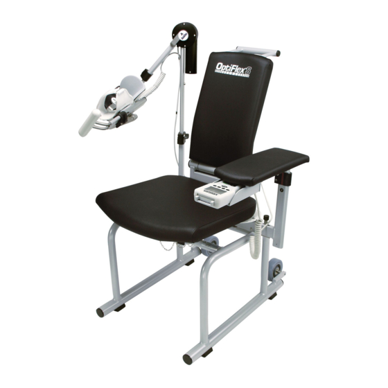
2. OptiFlex ® S description The motorized CPM device supports 1. Programming unit the following movements of the shoul- 2. Patient chip card der joint: 3. Compartment for storage of programming unit Adduction/abduction 0° - 30° - 175° 4. Armrest for healthy arm Internal/external 90°... -
Page 7: Description Of The Programming Unit
2.2 Description of the programming unit 2.2.1 Programming unit in normal mode patient chip card set angle of motor A set angle of motor B selected therapy therapy timer protocol set abduction set external value rotation value set adduction set internal value rotation value motor A - selected... - Page 8 2.2.2 Programming unit in MENU selection mode set carriage angle for set carriage angle for internal / external abduction/adduction rotation selected MENU level selectable parameters and the corresponding selection keys 2.2.3 Programming unit set to ROM programming current maximum selected function value selected for abduction or external rotation...
- Page 9 2.2.4 Programming unit in general programming mode selected function status of the selected function (here: speed)
- Page 10 2.2.3 Explanation of symbols Abduction Adduction Internal rotation External rotation Pause Timer Speed New patient Reverse on load - motor A Reverse on load - motor B Motor A ON/OFF Motor B ON/OFF Transport setting Synchronized/ non-synchronized mode Total therapy time Service menu...
-
Page 11: Explanation Of Symbols (Connections And Nameplate)
2.3 Explanation of symbols (connections and nameplate) -
Page 12: Safety Information
3. Safety information Definitions Warning! Read the safety statements before use Patient hazard — of the CPM device. The safety state- ments are classified as follows: – Only authorized individuals are allowed to operate the OptiFlex ® device. Individuals are authorized after receiving training in the opera- Danger! tion of the device and reading this... - Page 13 – It is not permitted to change the Warning! adjustment of 1 through 5 while a Shock hazard — patient is sitting in the CPM device. Strictly observe the following war- – Movements must not cause any nings. Failure to do so endangers the pain or irritation.
- Page 14 Warning! Caution! Equipment malfunction ⎯ Equipment damage ⎯ – Magnetic and electrical fields are – Check that the voltage and fre- capable of interfering with the quency ratings of your local power proper performance of the device. line are those indicated on the For this reason make sure that all nameplate.
-
Page 15: Device Setup
4. Device setup Note: For a better understanding of Setup with programmed chip card each step, please see also pages 2 and 3. Insert the original patient chip card (2) into the programming unit (1). 4.1 Connecting the device, Press the START key. performance check The device automatically enters the starting position (maximum adduction,... -
Page 16: Adjusting The Device To The Patient
• Set the armrest for the healthy arm to 4.2 Adjusting the device to a height that allows the patient to sit up straight (locking screw 14). the patient Note! For the following adjustments, the patient's arm should not yet be placed on the armrest. - Page 17 † Horizontal adduction/abduction Note! (Fig. A) If the elbow angle is changed to a flexion value of greater than or less It is the purpose of the adjustment than 90°, the setting for the upper arm procedures to accommodate the length will have to be changed, too.
-
Page 18: Setting The Treatment Values
5. Setting the treatment values - the reverse on load setting saved Warning! in the "Text" version is automati- Patient hazard ⎯ cally used for both motors Before therapy, a test run consisting - the key lock is disabled. of several exercise cycles must be completed without the patient. - Page 19 one of the parameter keys to select a Note! parameter: - Refer to sections 5.3 for a descrip- • The corresponding symbol appears tion of the parameters. on the display in a larger format. - To view the set parameter values, •...
-
Page 20: Programming Optiflex
5.2 Programming OptiFlex ® Note! • While you adjust the values, the Different programming levels are carriage will move to the set range. provided to program the OptiFlex ® This allows you to easily and quickly determine the ROM where the patient does not experience You change between levels by pressing pain. - Page 21 ■ Internal rotation the carriage will first move to the Maximum value: - 90 degrees maximum adduction position and to the position halfway between internal and external rotation. Then ■ External rotation the carriage will stop, allowing the Maximum value: 90 degrees patient to be positioned.
- Page 22 ■ Therapy timer Follow these steps to program pauses: • Access menu level 2, then press the Default setting is continuous parameter key to select the special operation. function A clock symbol in the upper right- • The display indicates the symbol for hand corner of the display identifies the special function and the selected the continuous mode of...
- Page 23 - Abduction: 41° Caution! - Adduction: 39° Patient hazard ⎯ - Internal rotation: 1° The reverse on load feature is a safety - External rotation: -1° measure to protect the patient in the - Pauses: event of cramps, spasms, locked joints and similar situations.
- Page 24 LEVEL 4: Caution! Patient hazard ⎯ The synchronized operation is recom- ■ Transport setting mended as a general rule. However, With this function, the carriage will medical and/or therapeutic indications move to a position optimally suited may call for the non-synchronized for packing the CPM device.
-
Page 25: Examples Of Use/Sample Protocols
position with the START key and 5.4 Examples of use/ initiate therapy by pressing the START key again. sample protocols 5.4.2 Isolated internal ro ta - 5.4.1 Isolated tion/ external rotation adduction/abduction 1. Complete the mechanical settings and adjust the carriage to the patient 1. - Page 26 Œ adjustment . Select a height at 5.4.3 Isolated elevation which the pivot points of motor A (flexion) and the shoulder are at the same level. c. Now open clamping lever (18) for 1. First adjust an angle of 90° for adjustment of the upper arm external rotation and deactivate Å...
-
Page 27: Care, Maintenance, Transport, Conversion
6. Care, Maintenance, Transport, Conversion 6.1 Care 6.2 Maintenance (fuse replacement) Warning! Check before each use Shock hazard – Unplug the device from the power line before cleaning. Shock hazard, equipment damage – Visually inspect the device for signs of Liquids must not enter the device or mechanical damage before each use. -
Page 28: Transport
6.3 Transport Fuse replacement The following operating steps must be Warning! completed before transporting the OptiFlex ® Patient hazard, equipment malfunc- 1. Activate the "transport setting" tion and damage — function in the menu (see The replacement of fuses must be also 5.3) and start the OptiFlex ®... - Page 29 13. Then close the box. Reverse the above steps to reassemble the device after transport. Warning! Shock hazard – Before use allow the OptiFlex ® S to reach room tempera- ture. If the device has been transpor- ted at temperatures below 0 °C (32 9.Only use the original shipping box for °F), leave it to dry at room tempera- transporting the device.
-
Page 30: Conversion
6. Open locking screw (20) and rotate 6.4 Conversion the forearm rest 180°. Tighten locking screw (20) (see conversion diagram Œ d). The OptiFlex ® S can be used on the left and on the right shoulder joint. How- 7. Hold the forearm rest and open ever, the device must be converted first. -
Page 31: Environmental Protection Statement
+ A1:1993 7. Environmental + A2: 1995 CSA No. Protection Statement 601.1-M90 UL 2601-1 The product described in this operation IEC 60601-1 manual must not be disposed of with (Electromagnetic 2:2001 unsorted household or municipal waste. compatibility) It requires separate disposal. Please contact CHATTANOOGA for information about the possible recycling of the Ambient conditions... -
Page 32: Iec 60601-1-2:2001
9. IEC 60601-1-2:2001 The OptiFlex ® S device is subject to If you detect damage or malfunctions particular precautions regarding electro- that may impair the safety of the patient magnetic compatibility (EMC). The or of the operator, have the device device must be installed and put into repaired before using it. -
Page 33: Electromagnetic Immunity
9.2 Electromagnetic immunity Guidance and Manufacturer’s Declaration – Electromagnetic Immunity OptiFlex ® S is intended for use in the electromagnetic environment specified below. It is the responsibility of the customer or user to ensure that the OptiFlex ® S device is used in such an environment. - Page 34 9.2 Electromagnetic immunity Guidance and Manufacturer’s Declaration – Electromagnetic Immunity OptiFlex ® S is intended for use in the electromagnetic environment specified below. It is the responsibility of the customer or user to ensure that the OptiFlex ® S device is used in such an environment.
-
Page 35: Recommended Separation Distances
9.3 Recommended separation distances Recommended separation distances between portable and mobile RF communications equip- ment and the OptiFlex ® S device The OptiFlex ® S is intended for use in an electromagnetic environment in which radiated RF disturbances are controlled. The customer or the user of the OptiFlex ®... -
Page 36: Technical Service
11. Technical Service 11.1 Technical hotline Do you have any technical questions? Do you need technical service? Chattanooga Technical Service Phone: 1-800-266-0026 ext. 6981 Fax: 1-423-870-7407 11.2 Shipment To prevent damage during transport, only use the original shipping box. These boxes can be obtained from CHATTANOOGA. - Page 38 Contenido Descripción del aparato Illustraciones 1. Informaciones sobre el uso de la tablilla de movilización 1.1 Posibilidades de aplicación 1.2 Objetivos de la terapia 1.3 Indicaciones 1.4 Contraindicaciones 2. Descripción del aparato OptiFlex ® 2.1 Explicación de los elementos funcionales 2.2 Explicación de la unidad de programación 2.3 Explicación de los pictogramas 3.
-
Page 39: Informaciones Sobre El Uso De La Tablilla De Movilización
1. Informaciones sobre el uso de la tablilla de movilización 1.3 Indicaciones 1.1 Posibilidades de aplicación La tablilla de movilización es adecuada El aparato OptiFlex ® S es una tablilla de para el tratamiento terapéutico de las movilización motorizada que permite un más frecuentes lesiones de la articula- movimiento pasivo continuo (Conti- ción del húmero así... -
Page 40: Descripción Del Aparato Optiflex
2. Descripción del aparato OptiFlex ® La tablilla de movilización motorizada 2.1 Explicación de los posibilita la realización de los siguientes movimientos en la articulación del elementos funcionales húmero: Aducción/Abducción 0° - 30° - 175° Nota: Rotación ¡Por favor véase también la página 2! interior/exterior 90°... -
Page 41: Explicación De La Unidad De Programación
28. Tornillo de apriete para el meca- nismo de giro 29. Mango 30. Clavijas hendidas de seguridad Modificaciones técnicas reservadas (06/2007) 2.2 Explicación de la unidad de programación 2.2.1 Unidad de programación en servicio normal Tarjeta chip del paciente Ángulo actual motor A Ángulo actual motor B Programa de terapia Indicador del tiempo... - Page 42 2.2.2 Unidad de programación en modo de selección de MENU Ángulo actual de la Ángulo actual de la tablilla tablilla de movilización de movilización en abduc- en rotación ción/aducción interior/exterior Nivel de MENÚ actual Parámetros disponibles y sus respectivas teclas 2.2.3 Unidad de programación en modo de programación «Magnitud de movimiento»...
- Page 43 2.2.4 Unidad de programación en modo de programación «General» Estado actual de la Función seleccionada función seleccionada (aquí: velocidad)
-
Page 44: Explicación De Los Pictogramas
2.3 Explicación de los pictogramas Véase también el cuadro sinóptico de pictogramas en la pág. U4a Abducción Aducción Rotación interior Rotación exterior Pausa Temporizador Velocidad Paciente nuevo Inversión de carga motor A Inversión de carga motor B Motor A On/Off Motor B On/Off Ajuste de transporte Modo de servicio... - Page 45 2.4 Explicación de símbolos (conexiones y placa de características)
-
Page 46: Indicaciones De Seguridad
3. Indicaciones de seguridad Explicación ¡Advertencia! Es sumamente importante que lea las Peligro para el paciente ⎯ indicaciones de seguridad antes de la puesta en marcha de la tablilla de – El aparato OptiFlex ® S sólo debe ser movilización. Las indicaciones de manejado por personal autorizado. - Page 47 – Después de almacenar los datos en – Los ajustes 1 a 5 sólo se deben la tarjeta chip del paciente, se tiene modificar cuando el paciente no se que escribir el nombre del paciente encuentre en la tablilla. sobre la tarjeta. Esta tarjeta sola- –...
- Page 48 – Al acoplar el aparato a otros apara- ¡Advertencia! tos o formar un conjunto de siste- Defectos de funcionamiento del mas médicos, tiene que estar aparato ⎯ garantizado de que no pueda surgir ningún peligro a causa de la suma- –...
- Page 49 ¡Precaución! Evitar huellas de presión o de roce ⎯ Preste atención en el caso de pacien- tes adiposos, especialmente en el caso de personas muy grandes o muy pequeñas, de evitar que se produzcan huellas de presión o de roce. Peligro para el paciente, deterioro de la tablilla ⎯...
-
Page 50: Ajustar El Aparato
4. Ajustar el aparato Nota: ¡Por favor véase las páginas 2 y Ajuste con una tarjeta chip ya 3 para una mejor aclaración de cada programada uno de los pasos! Inserte la tarjeta chip de paciente 4.1 Conexión del aparato, original (2) en la unidad de programa- ción (1). -
Page 51: Ajuste Del Aparato A Las Medidas Del Paciente
• Ajuste la altura del apoyabrazos del 4.2 Ajuste del aparato a las brazo sano de tal manera que el paciente esté sentado en posición medidas del paciente recta (tornillo de apriete 14). Nota: El brazo del paciente aún no debe encontrarse sobre el apoyabrazos al efectuar los siguientes ajustes. - Page 52 † Ajuste de la Nota: anteversión/retroversión (fig. A) Si usted modifica el ángulo del codo a (aducción/abducción horizontal) un valor de flexión superior o inferior a 90°, significa que también tiene que El objetivo de estos ajustes es propor- modificar el ajuste de longitud del cionarle al paciente el posicionamiento brazo.
-
Page 53: Ajustar Los Valores De Tratamiento
5. Ajustar los valores de tratamiento - la inversión de carga almace- Advertencia nada en la versión «Texto» auto- Peligro para el paciente ⎯ máticamente es adoptada para ambos motores. Antes de empezar el tratamiento se tiene que efectuar una prueba de - el bloqueo de teclas está... - Page 54 3. Para llamar el respectivo parámetro el ciclo de movimiento empieza de de tratamiento o las funciones, usted nuevo con el desplazamiento de la tiene que pulsar una de las 4 teclas tablilla hacia el máximo valor de de parámetros debajo del display. A aducción así...
-
Page 55: Programar La Versión Optiflex
NIVEL 3: Pacientes con tarjeta chip programada - Inversión de carga motor A • Realice primero los ajustes mecánicos - Inversión de carga motor B necesarios. - Motor A On/Off • Inserte ahora la tarjeta chip en el lector (el paciente aún no se debe - Motor B On/Off encontrar encima de la tablilla de movilización). - Page 56 NIVEL 1: • En el modo síncrono, después de accionar la tecla START la tablilla se desplaza primero hacia el ■ Abducción máximo valor de aducción y el Máximo valor: 175 grados valor medio entre rotación interior y exterior. Allí se detiene la tablilla para facilitarle al paciente la ■...
- Page 57 • A continuación vuelva a pulsar la NIVEL 2: misma tecla de parámetros. La marcación cambia automáticamente al renglón inferior para ajustar la ■ Pausas duración de la pausa de aduc- ción/rotación interior. Las pausas se hacen cada vez que se alcance uno de los valores máxi- En esta función la tecla de paráme- mos programados.
- Page 58 ■ Velocidad NIVEL 3: La velocidad se puede ajustar en pasos de 1% desde 1% hasta ■ Inversión de carga motor A 100%. El ajuste 100% equivale a (circuito de seguridad) 230°/minuto El aparato cambia automáticamente la dirección de movimiento (dirección Ajuste estándar: 100% opuesta) de ambos motores en cuanto la resistencia (carga) ocasio-...
- Page 59 ■ Modo de servicio Para un movimiento de rotación interior/exterior aislado, programar el síncrono/asíncrono motor A a la posición deseada Es posible conectar los motores A y (abducción/aducción) y desactivarlo B de manera sincrónica o asincró- a continuación. nica. Durante la terapia en el servicio normal de la tablilla el display mues- Síncrono: tra el símbolo «OFF»...
-
Page 60: Ejemplos De Aplicación/ Programación
¡Precaución! 5.4 Ejemplos de aplicación/ programación Peligro para el paciente ⎯ Nosotros, por principio, recomenda- mos que el aparato trabaje en el modo de servicio sincrónico. Puede 5.4.1 Aducción/abducción ser que el uso del modo de servicio aislada asíncrono esté indicado desde el punto de vista médico/terapéutico. - Page 61 8. Desactive el motor B pulsando para acceder al nivel 3 (M3). nuevamente la tecla de parámetros 7. Presione la tecla de parámetros «Motor B On/Off» o pulsando la «Motor A On/Off» para activar tecla «–». El signo en forma de V ja el parámetro.
- Page 62 tros «Motor B On/Off» o pulsando Nota: la tecla «–». El signo en forma de V ya no debe estar dentro del - Después de haber programado la círculo junto al respectivo sím- dimensión de los movimientos, bolo. usted puede programar otras opciones de programa como f.
-
Page 63: Conservación, Mantenimiento, Transporte, Reequipamiento
6. Conservación, mantenimiento, transporte, reequipamiento 6.1 Limpieza 6.2 Mantenimiento (cambiar los fusibles) Advertencia Control antes de cada uso Peligro de choque eléctrico – Siempre extraiga el enchufe de red de la respectiva caja de enchufe antes de Antes de cada uso, usted debe efectuar empezar a limpiar el aparato. -
Page 64: Transporte
Cambiar los fusibles Advertencia Peligro para el paciente, defectos de funcionamiento y/o deterioro del aparato Sólo técnicos expertos de acuerdo con lo estipulado en las normas DIN VDE 0105 o IEC 60364 o en normas equivalentes deben cambiar los fusibles (p.ej. técnicos de aparatos Fig. - Page 65 9. Para el transporte sólo se debe utilizar el embalaje original. La empresa Chattanooga no asume ninguna responsabilidad por daños 13. Cierre la caja de cartón. de transporte ocurridos sin haber Para el montaje del aparato después utilizado el embalaje original. del transporte, usted debe efectuar 10.
-
Page 66: Reequipamiento
5. Jale el elemento de movimiento 6.4 Reequipamiento hacia afuera y vuelva a introducirlo en el lado opuesto. Cierre el tornillo de apriete (14) (véase el esquema de El aparato OptiFlex ® S se puede utilizar reequipamiento † b, c). tanto para la articulación del húmero izquierdo como para la del húmero 6. -
Page 67: Indicaciones Respecto Al Medio Ambiente
Materiales: ABS, POM 7. Indicaciones (Delrin 100), respecto al medio PUR, PA, FR4, aluminio, acero ambiente fino inoxidable, latón NDD: clase 2a El producto descrito en estas instruc- ciones de uso no se debe eliminar En conformidad con: IEC 60601- conjuntamente con la basura doméstica 1:1990 corriente sin clasificar, sino que se tiene... -
Page 68: Iec 60601-1-2:2001
9. IEC 60601-1-2:2001 El aparato OptiFlex ® S está sujeto a En caso de que detecte un daño o un medidas de precaución especiales con defecto de funcionamiento que pueda respecto a la compatibilidad electro- poner en peligro la seguridad del magnética (CEM). - Page 69 9.2 Resistencia a las perturbaciones electromagnéticas Pautas y declaración del fabricante – Resistencia a las perturbaciones electromagnéticas El aparato OptiFlex ® S ha sido diseñado para el uso en el entorno electromagnético especificado a continuación. Es responsabilidad del cliente o usuario cerciorarse de que el aparato OptiFlex ®...
-
Page 70: Resistencia A Las Perturbaciones Electromagnéticas
9.2 Resistencia a las perturbaciones electromagnéticas Pautas y declaración del fabricante – Resistencia a las perturbaciones electromagnéticas El aparato OptiFlex ® S ha sido concebido para el servicio en un entorno electromagnético con las características especificadas a continuación. El cliente o usuario de OptiFlex ®... -
Page 71: Distancias De Seguridad Recomendadas
9.3 Distancias de seguridad recomendadas Distancias de seguridad recomendadas entre aparatos de radiocomunicación AF portátiles y móviles y el aparato OptiFlex ® El aparato OptiFlex ® S ha sido diseñado para el servicio en un entorno electromagnético, en el cual se controlan las magnitudes perturbadoras de AF radiadas. El cliente o usuario del aparato OptiFlex ®... -
Page 72: Servicio Técnico
11. Servicio técnico 11.1 Línea directa para Nota: preguntas técnicas Sólo personal técnico debidamente autorizado debe realizar las reparacio- nes. ¿Tiene alguna pregunta técnica? ¿Necesita ayuda de nuestro servicio La empresa CHATTANOOGA le ofrece técnico? cursillos de formación en todo lo referente al servicio técnico. - Page 74 Notas...
- Page 75 Notas...
- Page 76 Chattannoga Group • 4717 Adams Road • Hixson TN. 37343 • P h o n e 1 - 8 0 0 - 5 9 2 - 7 3 2 9 F a x 1 - 8 0 0 - 2 4 2 - 8 3 2 9 • w w w . c h a t t g r o u p . c o m...
Need help?
Do you have a question about the OptiFlex SHOULDER CPM and is the answer not in the manual?
Questions and answers