
Related Manuals for Unipart Dorman HD ALT

Summary of Contents for Unipart Dorman HD ALT
- Page 1 Heavy Duty Assisted Lift Trunnion Operation and Maintenance Manual C64.65546 Issue 5 May 2021...
-
Page 2: Table Of Contents
Signal Husbandry ........................34 Service and Repair ........................35 End of Life Disposal ........................35 Product Support ........................35 Appendix A - HD ALT/Signal Lifting Force Data ..............35 Heavy Duty Assisted Lift Trunnion Operation and Maintenance Manual Form Reference C64.65546 Issue 5.00... -
Page 3: Document Control
Document Control It is the reader’s responsibility to ensure they have the correct version of this document. If in doubt, please contact Unipart Dorman to verify the current issue status. Issue Number Dated Reason Jul 19 Initial Issue Sep 19 ... - Page 4 ALT) UTILISES TWO SPRING ASSEMBLIES TO PROVIDE ASISTANCE WHEN RAISING AND LOWERING THE SIGNAL BY HAND WHEN THE HD ALT IS IN THE HORIZONTAL POSITION KINETIC ENERGY IS STORED IN THE SPRINGS AND TO PREVENT RAPID DEPLOYMENT OF THIS, A SUITABLE HEAD AND POST SHALL BE FITTED TO PROVIDE A...
-
Page 5: Introduction
Any acquired knowledge of the Standard ALT shall not be used as a cross reference to the HD ALT. Separate O&M Manuals and Product Awareness Sessions are available for both Trunnions and these are available from Unipart Dorman. -
Page 6: Product Labelling
Product Labelling The following labels are applied to each HD ALT The RBK-211 padlock is not shown in this illustration for clarity Heavy Duty Assisted Lift Trunnion Operation and Maintenance Manual Form Reference C64.65546 Issue 5.00 5 of 39 Issue Date... -
Page 7: Safety
The weight of the HD ALT (165Kg) is clearly marked and installers should ensure that they have sufficient measures in place to ensure a safe lift. The marked weight is for the HD ALT only and does not include any pallet or packaging weight. - Page 8 INJURY AND ENDANGER LIFE DUE TO THE STORED ENERGY IN THE SPRING SYSTEM BEING RAPIDLY RELEASED The HD ALT shall not be used for any purpose other than that described in the introduction above. If it is used for any other purpose, Unipart Dorman will not accept any responsibility for damage, injury or death caused by the activity.
-
Page 9: Dimensions
Dimensions Heavy Duty Assisted Lift Trunnion Operation and Maintenance Manual Form Reference C64.65546 Issue 5.00 8 of 39 Issue Date May 2021... - Page 10 Heavy Duty Assisted Lift Trunnion Operation and Maintenance Manual Form Reference C64.65546 Issue 5.00 9 of 39 Issue Date May 2021...
-
Page 11: Description
Once the signal head and post are inserted and the HD ALT is in its vertical position the two sub-assemblies are secured together using 8 x M24 bolts and this action forms the main mounting interface between the signal and the foundation. - Page 12 Loading and Performance’). This, together with the restrictions on signal head configurations included within the generic F001, F002, and F003 submission, delivers a robust system that mitigates the risk of the safe working load on the Signal Post and HD ALT Assembly being exceeded.
-
Page 13: Storage And Movement
THE STORED ENERGY IN THE SPRING SYSTEM BEING RAPIDLY RELEASED The HD ALT is supplied on a large pallet as shown below and may be stored in the open air. The fasteners used to secure the unit to the pallet shall not be used as mounting hardware during installation and all packaging materials when removed, should be disposed of in accordance with local regulations. -
Page 14: Tooling
Tooling With the exception of the sighting scope, the only tools required to install a HD ALT onto a pre- prepared foundation are simple hand tools such as Torque Wrenches, 30mm and 36mm Sockets/Spanners. A RBK-221 key to remove the locking pin padlock will be required. -
Page 15: Foundation And Site Checks
Foundation and Site Checks Foundations should be secure and clear of any obstructions with studs fitted as shown in the Pre Installation Checks below. The laydown area for the signal shall not contain any obstacle or rising ground etc which would prevent the locking pin being inserted fully when the signal is reclined to its horizontal position A zone equivalent to the swept area of the signal being raised/lowered plus a reasonable margin either side to allow adequate footing for personnel engaged in the lift should be established. -
Page 16: Pre Installation Checks
Pre Installation Checks Prior to mounting the HD ALT a check shall be made with a spirit level to ensure that the foundation and therefore the top of all four mounting studs are level and at least 200mm of threaded stud is available above the foundation top. The mounting studs should be clean, free of damage and lubricated. -
Page 17: Installation
The signal and post should be checked for damage and any remaining transit packing materials should be removed and correctly disposed of. The HD ALT bore is to be free of debris or other obstruction and the Post Clamp should be loosened to enable the post to be inserted. -
Page 18: Raising &Lowering The Hd Alt
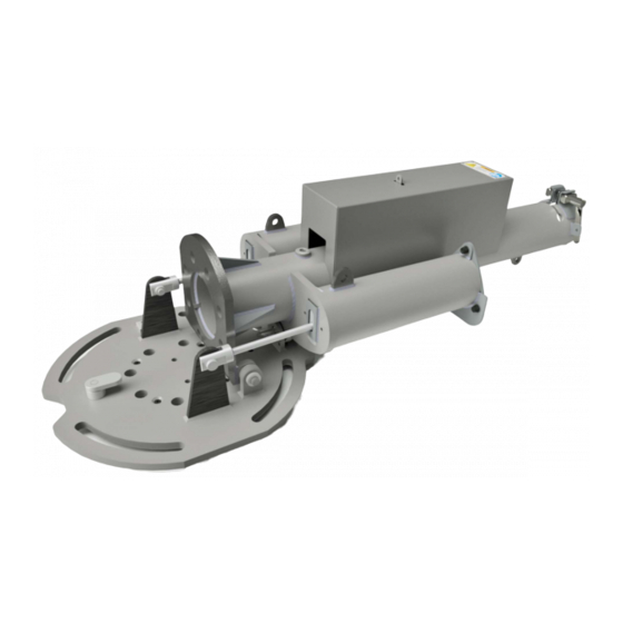
Using the lifting eyes highlighted in red shown in the image above, lift the HD ALT into position onto the four 24mm studs taking care to align the arrow marked on the Manufacturer Information Plate on the HD ALT baseplate parallel with the direction of the running rail. Then fit the remaining washers and nuts to secure it onto the studs Raising &Lowering the HD ALT... -
Page 19: Inserting The Post And Erecting The Signal
The bore of the HD ALT and the signal post should be checked for damage paying particular attention to the keyways on the post and the keys at the bottom of the HD ALT bore. Check the Plug Coupler and cable for damage, bent pins etc and any signs of moisture and then push them back into the bore of the post. - Page 20 Check that the post cannot rotate in the HD ALT bore and that the painted witness mark (indicated below) on the post is level with the top of the HD ALT. Do not fully tighten the locking collar until the signal is in the vertical position to allow for any settling.
- Page 21 To raise the assembled signal and HD ALT, position an adequate number of workers around the sign and have them ‘take the strain’ to control any movement of the signal and remove the retaining pin from the base plate.
-
Page 22: Electrical Connection
All mounting hardware should then be torque loaded to the values shown in the table in the Section “Torque Loadings”. Finally, hand tighten the HD ALT collar and secure with a padlock. Electrical Connection The infrastructure and signal cables are connected using standard plug couplers. To connect them, align the keyway and lug inside the connector shells then turn the locking collar by hand until an audible ‘click’... -
Page 23: Signal Alignment
Secure the cover with a padlock. The HD ALT should be bonded to earth if required by the use of bonding straps. No specific earth bonding arrangements to the signalling elements are required by virtue of the double insulated design, however a 17 mm through hole is provided on the base plate. - Page 24 Do not attempt to disassemble the scope to gain access to the internal lenses as this will disturb the optical alignment and the scope will need to be returned to Unipart Dorman for repair and recertification Heavy Duty Assisted Lift Trunnion Operation and Maintenance Manual Form Reference C64.65546...
- Page 25 If a camera and bracket are to be fitted to the scope for recording purposes then please refer to the instruction leaflet, part number C65.65569 available on the Unipart Dorman Website. Heavy Duty Assisted Lift Trunnion Operation and Maintenance Manual Form Reference C64.65546...
- Page 26 Using the alignment scope to provide visual cues, the signal is adjusted horizontally by rotating the base within the kidney slots and vertically by adjusting the angle of the HD ALT using the securing and adjustment nuts and the spherical washer sets shown in red.
- Page 27 The spherical washer sets are specified as a mandatory feature in the Network Rail Product Acceptance and are essential for the tilt adjustment. Therefore, they shall not be omitted. When the signal is aligned correctly to the point on the signal sighting form and any photographic records etc are obtained, ensure all of the mounting nuts are correctly torque loaded as shown below and the alignment scope is removed and stored in its protective case.
-
Page 28: Post Installation Checks
Post Installation Checks The Signal assembly has been designed for Plug and Play installation. Unipart Dorman recommends that the only test required is to have the signaller call on the aspects and ensure that the correct indications are displayed. This advice does not supersede any instructions issued by Network Rail. - Page 29 Withdraw the module sufficiently to access the inside of the signal head. If the signal is a four aspect variant, disconnect the plug coupler, which connects the two modules together. Remove and retain the cable clamps using a flat blade screwdriver Heavy Duty Assisted Lift Trunnion Operation and Maintenance Manual Form Reference C64.65546...
-
Page 30: Module Replacement (Other Signal Modules)
It is then possible to remove the module completely. As the cable is withdrawn, the tracer cord and plug coupler will travel up the post and when it reaches inside the signal head can be undone and the module fully removed. Tie the tracer cord to the plug on the new module and use it to pull the new cable down the bore of the post, guiding the cable through the slot in the post and into the connection box. -
Page 31: Additional Visors
Additional Visors Unipart Dorman iLS signals are designed to be very resistant to sunlight effects such as washout or phantom, there may be however, a very small number of signals that directly face East/West that may suffer from the effects of low winter sun. To mitigate these effects Unipart Dorman has a range of extended visors available. - Page 32 Colour Light Signal Cat Number Part Number Description 086/007488 B20.19436 CLS 600mm Extended Visor 086/007485 B20.19433 CLS 600mm Extended Visor 135° LH Obscuration 086/007486 B20.19434 CLS 600mm Extended Visor 135° RH Obscuration Junction Route Indicator Arms The JRI Visor Kit is available in Mark 1 or 2 variants and this is determined as shown in the Module replacement section above Heavy Duty Assisted Lift Trunnion Operation and Maintenance Manual Form Reference...
- Page 33 Cat Number Part Number Description 086/009514 D04.03540 iLS JRI Visor Fitting Kit Position 1 (Mk1 Indicators only) 086/009515 D04.03541 iLS JRI Visor Fitting Kit Position 4 (Mk1 Indicators only) 086/009516 D04.03542 iLS JRI Visor Array Fitting Kit Position 1 086/009517 D04.03543 iLS JRI Visor Fitting Kit Position 2 086/009518...
-
Page 34: Wedge Inserts
1.5° if required. Fitting the wedge is covered in a separate document available from Unipart Dorman. These inserts should only be ordered and fitted after consulting with the Signal Sighting Chair responsible for that particular signal. -
Page 35: Maintenance Activity
Signal Husbandry If the HD ALT/Signal requires any cleaning activity to be carried out, the only medium approved is water with the addition of proprietary soap based detergents if required. Do not use any solvent based or abrasive cleaning material as this may irreparably damage the signal. -
Page 36: Service And Repair
Product Support Unipart Dorman has developed a comprehensive support package including product overview and awareness sessions for the HD ALT and its signal range and this can be arranged by contacting Unipart Dorman using the details on the back page. - Page 37 It is not to be used as a generic or definitive document in its own right and Unipart Dorman cannot accept any responsibility for any loss of life, injury or damage caused by its use as such.
- Page 38 Heavy Duty Assisted Lift Trunnion Operation and Maintenance Manual Form Reference C64.65546 Issue 5.00 37 of 39 Issue Date May 2021...
- Page 39 Contact Us: Unipart Dorman Wennington Road Southport Merseyside United kingdom PR9 7TN T: +44 (0)1704 518000 E: dorman.enquiries@unipartdorman.co.uk ©Unipart Rail 2021 Heavy Duty Assisted Lift Trunnion Operation and Maintenance Manual Form Reference C64.65546 Issue 5.00 38 of 39 Issue Date...
Need help?
Do you have a question about the HD ALT and is the answer not in the manual?
Questions and answers