Advertisement
Quick Links
IMPORTANT: Read and follow all instruc-
tions and SAFETY PRECAUTIONS before
using this equipment. Retain for future
reference.
DESCRIPTION
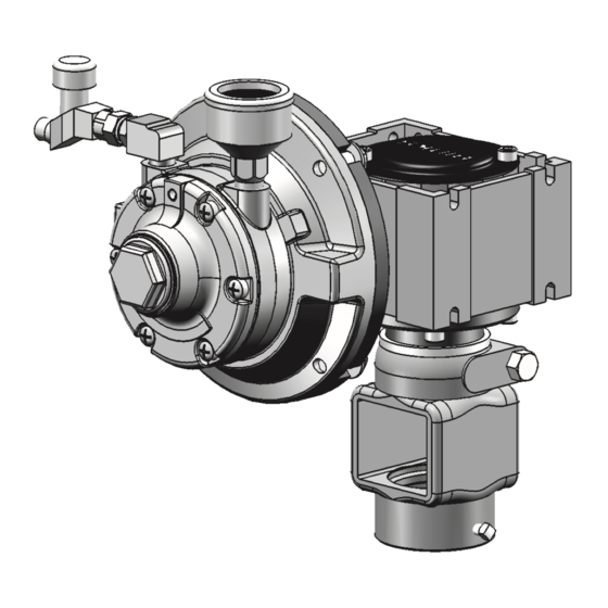
The QS-5001 air motor covered in this
service bulletin is designed to drive paint
agitators when connected to a source of
clean, dry, air pressure. Maximum air
input 100 PSI.
QS-5001 standard duty air motor drive,
1/4 h.p., 15:1 ratio, 20 to120 RPM for pres-
sure tank agitator. Includes air adjusting
valve with necessary hose and fittings for
hookup to tank regulator. Overall height
8", width 7-3/4".
High pressure can cause serious
injury. Pressure is maintained in
a pressure tank after the system
has been shut down. Before
attempting removal of fill plug
or cover, relieve tank pressure.
QS-5001 AIR MOTOR DRIVE
Pressure Relief Procedure
1.
Turn off the main air supply to the
tank.
2.
Close air inlet valve located on tank
air manifold.
3.
bleed off air in the tank by turning
the relief valve handle counter-
clockwise. Wait until all the air has
escaped through the valve before
removing the pressure tank cover
or fill plug.
4.
Leave the air relief valve open until
you have reinstalled the cover or fill
plug.
INSTALLATION
QS-5001 Installation onto Pressure Tank
with Agitator. (Refer to Figure 1.)
1. Place support (12) over agitator bear-
ing housing in tank lid and tighten in
place. Tighten setscrew (14) in either
screw hole.
2. Set air motor drive on support (12)
so that gear box shaft (35) engages
agitator shaft. Tighten cap screw (13).
3. For single regulation proceed as fol-
lows:
a. Remove air inlet valve from regula-
tor on tank and install service tee (1)
in regulator.
b. Reinstall air inlet valve in service
tee (1).
c. Install nipple (2) in service tee (1).
Install hose assembly (3) between
nipple and air adjusting valve (4) on
air motor.
4. For double regulation proceed as fol-
lows:
a. Remove plug from main line
port of lower regulator and install
nipple(2).
b. Install hose assembly (3) between
nipple (2) and air adjusting valve (4)
on air motor.
SERVICE bULLETIN
SB-19-085-P
Replaces Sb-19-085-N
OPERATION
Open valve to main air line; then slowly
open air adjusting valve until agitator
turns. To extend air motor life, adjust air
pressure setting to run motor at about one
revolution per second. The agitator should
be run continuously while using the tank.
PREVENTIVE MAINTENANCE
Air Motor Lubrication
Failure to properly lubricate
the air motor will result in
premature motor failure and
will void warranty.
Lubricate air motor daily by
adding 4 or 5 drops of SAE 10
weight oil into air inlet fitting.
Periodically - Remove air adjusting valve
and air strainer and flush motor with a
clean suitable solvent. Remove trapped
particles from screen in air inlet and clean
air strainer felt.
Air Motor Gear Box Lubrication
Every 2 Days - Remove oil fill plug and
check oil level. If oil level is low, add
140-weight SAE Gear Oil or a high quality
worm gear lubricant. Replace pipe plug
and tighten to 20 foot-pounds (27 N
of torque.
Note
Gear box oil is most easily
drained just after motor opera-
tion, while oil is still warm.
Approx. 1/8" Gap
(top of oil level to
bottom of fill hole)
Note
Do not overfill. Overfilling may
cause oil to leak out of vent cap
on top of gear box.
m)
.
Advertisement

Related Manuals for DeVilbiss QS-5001

Summary of Contents for DeVilbiss QS-5001
- Page 1 The QS-5001 air motor covered in this 2. Set air motor drive on support (12) service bulletin is designed to drive paint Air Motor Gear Box Lubrication...
-
Page 2: Safety Precautions
PAGE 2 Sb-19-085-P SAFETY PRECAUTIONS This manual contains important information that all users should know and understand before using the equipment. This informa- tion relates to USER SAFETY and PREVENTING EQUIPMENT PRObLEMS. To help you recognize this information, we use the following terms to draw your attention to certain equipment labels and portions of this Service bulletin. -
Page 3: Replacement Of Parts
Sb-19-085-P PAGE 3 After first 250 hours of operation, remove Gear Box (Refer to Figure 3.) gear box and drain gear oil. Refill gear box with 140-weight SAE Gear Oil or a Remove oil fill plug (37) or cover plate high quality worm gear lubricant. - Page 4 PAGE 4 Sb-19-085-P FIGURE 1 GEAR DRIVE AIR MOTOR QS-5001 (STANDARD DUTY) See Figure 3 for Gear box Assembly Fill Figure 2 for Air Motor. Replacement Ind. Parts Part No. Description Req'd. Service Tee 1/4" Galvanized Purchase Locally H-2008 Nipple 1/4" NPS(M) x 1/4"...
- Page 5 Sb-19-085-P PAGE 5 FIGURE 2 QS-4016 AIR MOTOR Replacement Ind. Parts Part No. Description Req'd. QS-336 Oil Seal QS-197 bearing Purchase Locally Machine Screw 1/4-28 x 1/2 QS-334 End Plate QS-189-1-K10 Dowel Pin (Kit of 10) • PT-59-K10 End Plate Gasket Kit (Kit of 10) •...
- Page 6 PAGE 6 Sb-19-085-P FIGURE 3 GEAR BOX ASSEMBLY When Replacing Ref. No. 31, Torque to 15 in-lbs. min. When Replacing Ref. No. 40, Torque to 60 in-lbs. min. Apply SS-9868 Sealant to Threads as Needed. Motor Shaft Replacement Ind. Parts Part No.
- Page 7 Sb-19-085-P PAGE 7 AIR MOTOR DRIVE SERVICE CHECKS CONDITION CAUSE CORRECTION A. Air motor sluggish or inefficient. 1. Air motor needs cleaning. 1. Disassemble and clean per parts replacement instruc-tions. 2. Motor vanes need replacing or 2. Disassemble, clean motor per parts contaminants present in motor replacement instructions.
-
Page 8: Warranty
Repair Kit PT-77-K10 End Plate PT-59-K10 End Plate Gasket Kit Directly. O-Ring WARRANTY This product is covered by DeVilbiss’ 1 Year Limited Warranty. DeVilbiss Sales and Service: www.devilbiss.com U.S.A./Canada Customer Service Toll Free Customer Service and Technical Support 195 Internationale Blvd.
Need help?
Do you have a question about the QS-5001 and is the answer not in the manual?
Questions and answers