
Summary of Contents for Altec LMAP
- Page 1 Altec LMAP (Load Moment and Area Protection) Telescopic Boom Cranes Operation Courtesy of CraneMarket.com...
- Page 2 Greer Part Number: W450240A Courtesy of CraneMarket.com...
-
Page 3: Table Of Contents
Display ......................................1 Extension Sensor ..................................2 Function Kick-Out ..................................2 Pressure Transducers ................................2 Operator Alarms ..................................2 LMAP Display ....................................3 Operation ......................................5 Power Up Self-Test ................................... 5 Adjusting Brightness & Contrast ............................. 5 Stowing the Jib................................... 6 Erecting the Jib .................................. - Page 4 Courtesy of CraneMarket.com...
-
Page 5: Introduction
• Cables The Load Moment Area Protection (LMAP) system is intended to aid the crane operator by continuously monitoring the load and warning of an approach to an overload or two-block condition. Crane functions are monitored by means of high accuracy sensors. The system continuously compares the load suspended below the boom head with the crane capacity chart stored in the computer memory. -
Page 6: Extension Sensor
On-screen messages provide the operator with visual warnings of conditions that occur during operation of the system. Extension Sensor The extension sensor provides an increasing voltage proportional to the extension of the boom. A cable attached to the boom head provides a low current electrical path for the ATB signal. Function Kick-Out Electrically operated solenoids disconnect the control lever functions for boom hoist lower, telescope out, and winch up whenever an overload or an ATB condition occurs. -
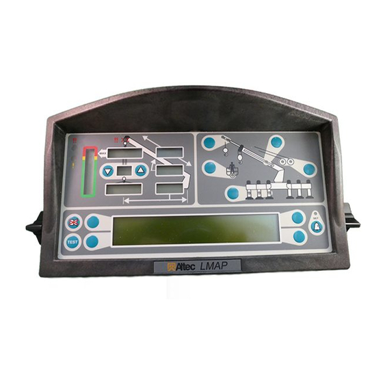
Page 7: Lmap Display
Boom Angle – Displays the current boom angle in degrees and tenths of a degree. Load Radius – Displays the load radius from centerline of rotation. Crane Setup – These keys are used in the setup process to configure the LMAP system to match the current configuration of the crane. - Page 8 YOu MuST uSE ThE CrAnE SETuP MODE TO COrrECTLY SET ThE LMAP SYSTEM FOr PrOPEr OPErATIOn. ThE LMAP SYSTEM SETuP MuST MATCh ThE ACTuAL COnFIgurATIOn OF ThE CrAnE SO ThAT IT WILL InDICATE ThE COrrECT hOOK LOAD AnD LIFTIng CAPACITY OF ThE CrAnE.
-
Page 9: Operation
Operation Power up Self-Test Immediately following electrical power up, or by manually pressing the key, the system will TEST execute a self-test lasting for approximately eight seconds. TEST TEST During this time, the numerical display segments and bar graph segments are all turned on, the audible alarm will sound, and alarm indicator lights and all other LED’s are illuminated. -
Page 10: Stowing The Jib
If the key is pressed when ERECTED JIB NOTE the LMAP System does not have a stowed jib selected, the message “There Is No Stowed Jib To Erect” will appear in the TEST information window. -
Page 11: Setting The Parts Of Line
Setting the Parts of Line PARTS OF LINE Parts of line are set by pressing the up or down arrow. The number of parts of line will appear in the display next to the arrow. When an alternate winch is selected, it is necessary to reset the parts of line for the alternate winch. -
Page 12: Operator Alarms
Operator Alarms mWArnIng ALL OPErATOr DEFInED ALArMS ArE WArnIng DEvICES. ALL CrAnE FunCTIOnS rEMAIn OPErATIOnAL WhEn An OPErATOr ALArM IS ACTIvE. Accessing the Operator Alarms Press the key to access the OPERATOR ALARM operator alarms. The information window will show the current status of the alarms. -
Page 13: Setting Maximum Boom Length Alarm
Setting Maximum Boom Length Alarm Extend the boom to the desired maximum length. Press the key to access the OPERATOR ALARM operator alarm screen. Press the key adjacent to “Max Length” to set to the current position. If the length of the boom increases beyond the maximum length set, the red warning light will flash TEST and the audible alarm will sound. -
Page 14: Swing Alarms
Swing Alarms Swing alarms define a working arc and an exclusion zone by two set points. The following diagram illustrates the working arc and exclusion zone. Right Swing • A left swing alarm is activated when swinging to the left. WORKING •... - Page 15 Press the key adjacent to “Set Left and Right Alarms?”. 12,900 31.0 77.5 1,000 SET LEFT AND RIGHT ALARMS? NEXT SET WORKING AREA ALARM? NEXT TEST Set Left And Right To set a new swing area, you must first reset the left and right points.
-
Page 16: Enabling The Preset Exclusion Zones
Press the key adjacent to “Next” to proceed. 12,900 31.0 77.5 1,000 CURRENT SWING ANGLE EXIT NEXT TEST Next Rotate the boom to the right swing point and press the key adjacent to “Off”. 31.0 12,900 77.5 1,000 SWING RIGHT AND SET RIGHT POINT CURRENT SWING ANGLE EXIT TEST... - Page 17 Press the key adjacent to “Swing Alarms”. 12,900 31.0 77.5 1,000 SWING ALARMS WORKING AREA ALARM TEST Press the key adjacent to “Preset Working Area”. 12,900 31.0 77.5 1,000 PRESET WORKING AREA SET WORKING AREA MANUALLY TEST Press the key adjacent to one of the four predefined exclusion zones: Front, Rear, Curbside, 31.0 12,900...
-
Page 18: Setting The Swing Left And Swing Right Alarms
WORKING AREA For example, selecting “Front” will set the working area from 270° through 90° and set the exclusion zone as shown in the illustration. 270° 90° EXCLUSION ZONE Confirm your selection by pressing the key adjacent to “Yes”. This will cancel all existing swing alarms 31.0 12,900 including manually set alarms. - Page 19 Press the key adjacent to “Swing Alarms”. 12,900 31.0 77.5 1,000 SWING ALARMS WORKING AREA ALARM TEST Press the key adjacent to “Set Working Area Manually”. 12,900 31.0 77.5 1,000 PRESET WORKING AREA SET WORKING AREA MANUALLY TEST To set a new swing area, you must first reset the left and right points.
- Page 20 Move the boom to the middle of the swing area and press the key adjacent to “Set”. 12,900 31.0 77.5 1,000 SWING TO THE MIDDLE OF SAFE AREA & STOP SET CURRENT SWING ANGLE EXIT TEST Set Middle Swing Press the key adjacent to “Next” to proceed. 12,900 31.0 77.5...
-
Page 21: Setting The Work Area Alarm
Setting the Work Area Alarm This alarm, when set properly, enables the operator to define a safe operating zone by setting only two points. This results in an enhanced work area and defines the exclusion zone area. The exclusion zone area can be visualized by connecting the two set points with a horizontal line and extending the line upwards to create a vertical plane or wall. - Page 22 Press the key adjacent to “Set Working Area Alarm”. 12,900 31.0 77.5 1,000 SET LEFT AND RIGHT ALARMS? NEXT SET WORKING AREA ALARM? NEXT TEST Set Working Area To set a new working area, you must first reset 31.0 12,900 the left and right points.
- Page 23 To turn off the Working Area Alarm, press key twice to access the OPERATOR ALARM 12,900 31.0 Working Area Alarm menu. 77.5 1,000 FULL SPAN OUTRIGGERS MAIN BOOM STOWED 31' JIB TEST Operator Alarm Button Press the key adjacent to “Set Working Area Alarm”.
- Page 24 Courtesy of CraneMarket.com...
Need help?
Do you have a question about the LMAP and is the answer not in the manual?
Questions and answers