Table of Contents
Advertisement
Quick Links
L
R
OGIC
AIL
TECHNOLOGIES
21175 Tomball Pkwy
Suite 287
Houston, TX 77070
Getting started
Thank you for purchasing a Logic Rail Technologies product! Please familiarize yourself with all the instructions prior to
installing this board. This version of the Block Animator (model BA-1) provides 3-color signaling for LED-based 3-light
(common anode/positive) and searchlight-style signals. It can also be used with LED-based 2-light (common anode/positive)
signals; of course then you'll only get 2-color signaling.
The Block Animator (BA) provides automatic operation of two 3-color block signals in a semi-prototypical way. Four pairs
of Infrared (IR) emitters and detectors are used for bidirectional train detection. Detection is achieved when the IR beam from
the emitter reflects off the underside of the train back down to the detector.
could still encounter false triggering from overhead lighting. This is usually eliminated with angled sensor mounting
and/or proper sensor sensitivity adjustment (page 4).
or 9-12V DC power source (such as our 12VPSR). Do NOT exceed these limits! The layout of the signals and IR
components is illustrated at left below; the illustration on the right is a side view of the IR detection method.
The BA operates the signals as described next. In the absence of any trains the two signals will be green. Now consider a
train traveling eastbound. When sensor W1 is activated signal WB will change from green to red and will remain red as the
train continues eastbound and subsequently activates sensor W2. When the train then activates sensor E2 signal EB will
change from green to red. Once the train has totally cleared sensors W1 and W2 then signal WB will change from red back to
green. As the train continues eastbound towards sensor E1 signal EB will remain red. Once the train has passed over sensor
E1 and totally clears both it and sensor E2 signal EB will change to yellow; this mimics the behavior of the train entering the
"next block." After a time delay (10 or 30 seconds; see below) signal EB will change to green. Signal operation for a
westbound train is similar with signal EB changing from green to red and back to green while signal WB changes from green
to red to yellow and back to green.
You should make all of the connections to the BA before applying power to it. You can mount the BA anywhere it is
convenient underneath your layout using the four mounting holes provided. The holes will accept #4 screws; do not enlarge
the holes as damage to the circuit board can result and your warranty will be voided!
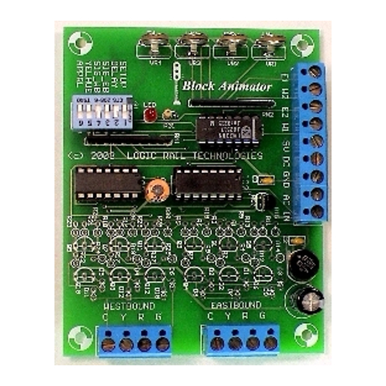
The BA board has a set of 6 configuration switches on it. Each switch is described below.
Switch Name
SETUP
DELAY
Yellow to Green delay is 30 seconds
SIG_EB
SIG_WB
YELHUE
Yellow hue for searchlight signals is more reddish
APPRL
Approach Lighting
The concept of Approach Lighting is quite simple. A signal remains dark (not illuminated) until a train approaches it (i.e. the
block in advance of the signal is occupied). This has been primarily used in the western U.S. in remote locations where signal
equipment operates on battery power. Having the signals unlit most of the time saves battery power as well as prolongs the
life of the bulbs. The "rule" for illumination is simple: the signal shall be illuminated when the preceding block is occupied.
The BA supports this feature (when the APPRL switch is ON/CLOSED) and works as follows. Signal EB will be illuminated
whenever an eastbound train activates sensor W1 and will keep signal EB illuminated until sensor E2 is activated and then
subsequently cleared. Note that if the eastbound train activates and then clears sensor W1 but after 35 seconds hasn't
TM
"Sophisticated
Model Railroad
Electronics"
Phone: (281) 251-5813
email: info@logicrailtech.com
http://www.logicrailtech.com
Meaning when OFF/OPEN
BA is in normal operating mode
EB signal is a 3-color type
WB signal is a 3-color type
Approach Lighting is Disabled
Block Animator (BA-1)
- Infrared detection version
Instructions
Despite the use of infrared components you
This version of the BA must be powered from either a 7-9V AC
Meaning when ON/CLOSED
Yellow to Green delay is 10 seconds
EB signal is a searchlight type
WB signal is a searchlight type
Yellow hue for searchlight signals is more greenish
Approach Lighting is Enabled
Revised 10/20/18
BA is in sensor setup mode
Advertisement
Table of Contents

Related Manuals for LOGIC RAIL BA-1

Summary of Contents for LOGIC RAIL BA-1
- Page 1 Revised 10/20/18 Getting started Thank you for purchasing a Logic Rail Technologies product! Please familiarize yourself with all the instructions prior to installing this board. This version of the Block Animator (model BA-1) provides 3-color signaling for LED-based 3-light (common anode/positive) and searchlight-style signals. It can also be used with LED-based 2-light (common anode/positive) signals;...
- Page 2 activated sensor E2, then the BA will assume the train has actually reversed direction and will turn the signal off. Similarly, signal EB will also be illuminated whenever a westbound train activates sensor E2 and will keep signal EB illuminated until sensor W1 is activated and then subsequently cleared.
- Page 3 Signals with 2 LEDs (Tomar Industries, Oregon Rail Supply, etc) To select signals using 2 individual LEDs you must have the appropriate switch in the OFF/OPEN position. The BA directly controls 2-light LED signals wired in a common anode (the anode is the positive side of the LED) arrangement. Virtually all brands of 2-light signals are wired this way.
- Page 4 Figure 5 below illustrates the wiring for one set of IR components (shown for sensor location “E1”). Use the same wiring scheme for the three remaining sensor locations (E2, W1, W2). Four 180 ohm 1 Watt resistors are included with the BA. WARNING: The 180 ohm 1 watt resistor may become hot to the touch –...
- Page 5 Power The BA accepts 7-9V AC or 9-12V DC power. Power consumption for LED signals is approximately 360mA (including the signals). If you are only using a single BA then use the TWO AC terminals to provide power (polarity doesn’t matter). CAUTION: Most AC or DC accessory terminals on your throttle/power pack exceed 12V and cannot be used with the BA! However, you can use those power sources in conjunction with our 12VPSR which will provide 12V DC.
- Page 6 This product is warranted to be free from defects in materials or workmanship for a period of one year from the date of purchase. Logic Rail Technologies reserves the right to repair or replace a defective product. The product must be returned to Logic Rail Technologies in satisfactory condition.
Need help?
Do you have a question about the BA-1 and is the answer not in the manual?
Questions and answers