Ormazabal cpg.0 General Instructions Manual
Hide thumbs
Also See for cpg.0:
- General instructions manual (68 pages) ,
- General instructions manual (60 pages) ,
- General instructions manual (60 pages)

Related Manuals for Ormazabal cpg.0


Summary of Contents for Ormazabal cpg.0
- Page 1 GIS medium-voltage switchgear, gas insulated, up to 40.5 kV, in accordance with IEC Standard General instructions IG-123-EN, version 11, 23/07/2021...
- Page 2 Therefore, the use of this equipment poses electrical, mechanical and thermal risks. In order to ensure an acceptable level of protection for people and property, and in compliance with applicable environmental recommendations, Ormazabal designs and manufactures its products according to the principle of integrated safety, based on the following criteria: •...
-
Page 3: Table Of Contents
6.6.3. cpg.0-v 2500 A......26 6.6.4. cpg.0-c ........26 6.6.5. -
Page 4: General Description
GIS medium-voltage switchgear, gas insulated, up to 40.5 kV, in accordance with IEC Standard General description The cpg.0 switchgear is made up of a series of gas- lled GIS cubicles for primary distribution in medium-voltage networks up to 40.5 kV. 1.1. Models... -
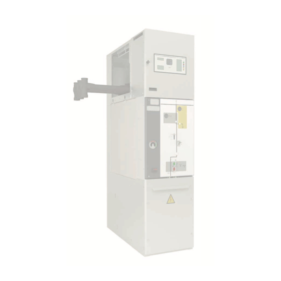
Page 5: Main Components
40.5 kV, in accordance with IEC Standard 1.3. Main components Busbar compartment Gas tank Gas pressure relief duct Cable compartment Control compartment Driving mechanisms compartment Figure 1.1. Main elements of cpg.0 cubicles IG-123-EN version 11; 23/07/2021... - Page 6 General description General instructions cpg.0: GIS medium-voltage switchgear, gas insulated, up to 40.5 kV, in accordance with IEC Standard Gas tank This is a sealed compartment, made of stainless steel and sealed for life, which houses the switching and breaking switchgear, with gas as the insulating medium.
- Page 7 General instructions General description cpg.0: GIS medium-voltage switchgear, gas insulated, up to 40.5 kV, in accordance with IEC Standard Cable compartment Located in the bottom part of the cubicle, this has a cover, interlocked with the earthing circuit, which allows front access to the medium-voltage cables.
- Page 8 Figure 1.7. Fuses compartment detail Exterior cable connections (bushing) cpg.0 cubicles have bushing on the front for medium- voltage cable connection. These are made of epoxy resin and can, thanks to their con guration, withstand the current transformers. They are duly screened and designed in line with Standard EN 50181, type "C".
- Page 9 (cpg.0-rcd, right cable riser) models. 800 mm . These side bushings do not allow it to withstand current transformers. Figure 1.11. Left-side cable riser cubicle (cpg.0-rci) for cpg.0-vl cubicle Figure 1.9. Side bushings in cpg.0-vl for connection of medium-voltage cables Figure 1.12.
- Page 10 General description General instructions cpg.0: GIS medium-voltage switchgear, gas insulated, up to 40.5 kV, in accordance with IEC Standard Gas pressure relief duct (optional) The entire cubicle is prepared to withstand an internal arc in A ue made of metal sheet, which conducts the gases the tank up to 31.5 kA - 1 s...
- Page 11 General instructions General description cpg.0: GIS medium-voltage switchgear, gas insulated, up to 40.5 kV, in accordance with IEC Standard Driving mechanism In addition to a mimic diagram customised for each type of function, this has the driving elements in its middle section:...
-
Page 12: Technical Characteristics
Isolating distance Lightning impulse [U Between phases Isolating distance Models cpg.0-vl, cpg.0-f, cpg.0- and cpg.0-rc are not available for 40.5 kV rated voltage models. Table 2.1. Table of electrical characteristics common to cpg.0 family For rated voltage cpg.0-v cpg.0-vl cpg.0-c cpg.0-f... - Page 13 General instructions Technical characteristics cpg.0: GIS medium-voltage switchgear, gas insulated, up to 40.5 kV, in accordance with IEC Standard For 36 kV voltage cpg.0-v cpg.0-vl cpg.0-c cpg.0-s cpg.0-f cpg.0- cpg.0-pt cpg.0-rb cpg.0-rc Rated current [I 1250 1250 1250 1250 1250...
-
Page 14: Name Plate
Weight of insulating uid (g) Year Year of manufacture Thermal class Internal arc classi cation (*) This number should be reported to Ormazabal in the event of incident. Table 2.6. List of information shown on the name plate IG-123-EN version 11; 23/07/2021... -
Page 15: Mechanical Ratings
1365* 2425 1365* 2425 1365* (*) 1410 mm in the case of cubicles with IAC AFLR rating. (**) 1447 mm in the case of cubicles with IAC AFLR rating. Table 2.7. Dimensions and weights of cpg.0 IG-123-EN version 11; 23/07/2021... -
Page 16: Ip Rating
Technical characteristics General instructions cpg.0: GIS medium-voltage switchgear, gas insulated, up to 40.5 kV, in accordance with IEC Standard 2.3. IP rating All power circuit elements are installed inside a stainless steel gas tank, providing a IP65 rating. The standard degree of protection for the cubicle assembly, in all designations, is IP3X, optionally reaching IP4X. -
Page 17: Normal Service Conditions
Vibrations caused by causes external to the switchgear or by seismic movements (a) For special service conditions (ambient temperature above + 40°C, installation, storage or transport altitude over 1000 m above sea level, signi cant pollution level, or others di erent to those described), check with Ormazabal. Table 3.1. -
Page 18: Handling And Transport
Always in upright position, directly perfectly balanced at all times. 4.2. Lifting means cpg.0 cubicles can be handled either by lifting (with slings) or using a forklift truck (with pallet): Figure 4.1. Lifting a cpg.0 cubicle with chains Figure 4.2. - Page 19 Lifting a cpg.0-c cubicle with a speci c tool Figure 4.5. Wheel anchors in the cubicle Figure 4.4. Lifting a cpg.0-c cubicle using a forklift truck and speci c tool Figure 4.6. Positioned wheel detail Elevating castor wheels can be used to put the cubicles in their nal position.
-
Page 20: Storage
Storage General instructions cpg.0: GIS medium-voltage switchgear, gas insulated, up to 40.5 kV, in accordance with IEC Standard Storage If it needs to be stored, the material must be placed on dry After prolonged storage, clean all the insulating parts ground or damp-proof insulating material, still in its original carefully before commissioning the equipment. -
Page 21: Installation
1. Using a blade, cutter or similar tool, cut the cellophane the cubicle is wrapped in. 6.2. List of assembly materials supplied A box is supplied along with the cpg.0 switchgear with all 3. Earthing bars. the material necessary for installation and correct operation. -
Page 22: Minimum Installation Distances
Installation General instructions cpg.0: GIS medium-voltage switchgear, gas insulated, up to 40.5 kV, in accordance with IEC Standard 6.3. Minimum installation distances The minimum distances to the walls and ceiling, in Minimum distances [mm] accordance with Standard IEC-62271-200 Annex AA, are as... -
Page 23: Recommended Dimensions
General instructions Installation cpg.0: GIS medium-voltage switchgear, gas insulated, up to 40.5 kV, in accordance with IEC Standard 6.4.1. Recommended dimensions Minimum recommended dimensions based on the trench Minimum distances [mm] dimensions used in the tests in accordance with Standard Trench IEC 62271-200. -
Page 24: Joining The Cubicles
Hexagonal nut and bolt detail Figure 6.9. Detail of the two connected cubicles The assembly sequence for the busbar and the busbar compartment enclosure is described in Ormazabal's RA-283 Spares and accessories instructions document. Figure 6.7. Detail of the hexagonal bolt in place Figure 6.8. -
Page 25: Cpg.0-V 24 Kv 630 A
The xing points for circuit-breaker cubicles up to 630 A are de ned in Figure 6.10: Figure 6.10. Fixing points 6.6.2. cpg.0-v 1250 A and 1600 A/cpg.0-pt/cpg.0-vl xing points for 1250 and 1600 A circuit-breaker cubicles are de ned in Figure 6.11: Figure 6.11. Fixing points with side connection... -
Page 26: Cpg.0-V 2500 A
Installation General instructions cpg.0: GIS medium-voltage switchgear, gas insulated, up to 40.5 kV, in accordance with IEC Standard 6.6.3. cpg.0-v 2500 A The xing points for 2500 A circuit-breaker cubicles are de ned in Figure 6.12: Figure 6.12. Fixing points 6.6.4. -
Page 27: Cpg.0-S
General instructions Installation cpg.0: GIS medium-voltage switchgear, gas insulated, up to 40.5 kV, in accordance with IEC Standard 6.6.5. cpg.0-s The xing points for disconnector cubicles are de ned in Figure 6.14: Figure 6.14. Fixing points 6.6.6. cpg.0-f/cpg.0-fl The xing points for fuse-protection cubicles are de ned in Figure 6.15:... -
Page 28: Cpg.0-Rb
Installation General instructions cpg.0: GIS medium-voltage switchgear, gas insulated, up to 40.5 kV, in accordance with IEC Standard 6.6.7. cpg.0-rb The xing points for busbar riser cubicles are de ned in Figure 6.16. Figure 6.16. Fixing points IG-123-EN version 11; 23/07/2021... -
Page 29: Equipment Earthing
General instructions Installation cpg.0: GIS medium-voltage switchgear, gas insulated, up to 40.5 kV, in accordance with IEC Standard 6.7. Equipment earthing The switchgear has an earth collector at bar connected to the system's general earth. Earthing bars between cubicles Earthing bars 24 kV 630 A cubicles joint to other cubicles Earth braid 24 kV - 630 A cubicles joint to busbar coupling Figure 6.17. -
Page 30: Cable Connection
Installation General instructions cpg.0: GIS medium-voltage switchgear, gas insulated, up to 40.5 kV, in accordance with IEC Standard 6.8. Cable connection The cables are connected to the bushings with IEC type reinforced connection connectors (screwable). Never touch live connectors, not even screened connectors. - Page 31 General instructions Installation cpg.0: GIS medium-voltage switchgear, gas insulated, up to 40.5 kV, in accordance with IEC Standard Continuation Max. diameter Max. rated Total on insulation Cubicle Manu- Connector Nº Terminal current connector Connector admitted by model facturer series terminals...
- Page 32 Installation General instructions cpg.0: GIS medium-voltage switchgear, gas insulated, up to 40.5 kV, in accordance with IEC Standard Continuation Max. diameter Max. rated Total on insulation Cubicle Manu- Connector Nº Terminal current connector Connector admitted by model facturer series terminals...
- Page 33 General instructions Installation cpg.0: GIS medium-voltage switchgear, gas insulated, up to 40.5 kV, in accordance with IEC Standard Continuation Max. diameter Max. rated Total on insulation Cubicle Manu- Connector Nº Terminal current connector Connector admitted by model facturer series terminals...
- Page 34 Installation General instructions cpg.0: GIS medium-voltage switchgear, gas insulated, up to 40.5 kV, in accordance with IEC Standard Continuation Max. diameter Max. rated Total on insulation Cubicle Manu- Connector Nº Terminal current connector Connector admitted by model facturer series terminals...
- Page 35 General instructions Installation cpg.0: GIS medium-voltage switchgear, gas insulated, up to 40.5 kV, in accordance with IEC Standard Continuation Max. diameter Max. rated Total on insulation Cubicle Manu- Connector Nº Terminal current connector Connector admitted by model facturer series terminals...
-
Page 36: Installing The Gas Duct To Outside The Cubicle
IEC Standard 6.9. Installing the gas duct to outside the cubicle room Ormazabal's scope of supply includes a 250 mm long duct section from the side panel. In general, supply and assembly of the rest of the ducts are not included in Ormazabal's scope of supply. - Page 37 IEC Standard CAREFUL, INSTALLER! Follow the recommendations below when designing the part of the ducts NOT included in Ormazabal's scope of supply: 1. The ducts must exit to an adjacent room or to outside the room where the cubicles are installed.
-
Page 38: Operations Sequence
IEC Standard Operations sequence 7.1. Operating and commissioning sequence 7.1.1. Disconnector function operating sequence (cpg.0-s) For standard cubicles: cpg.0-s up to 36 kV/1250 A/25 kA • cpg.0-s 40.5 kV/1250 A/25 kA • cpg.0-s up to 40.5 kV/1250 A/31.5 kA •... - Page 39 General instructions Operations sequence cpg.0: GIS medium-voltage switchgear, gas insulated, up to 40.5 kV, in accordance with IEC Standard a. Manual feeder disconnector operation The FEEDER DISCONNECTOR manual driving lever is identi ed using the symbol area GREY colour. Figure 7.2.
- Page 40 Operations sequence General instructions cpg.0: GIS medium-voltage switchgear, gas insulated, up to 40.5 kV, in accordance with IEC Standard b. Manual earthing switch operation The EARTHING SWITCH manual driving lever is identi ed in YELLOW in the symbol area. Figure 7.5.
- Page 41 GIS medium-voltage switchgear, gas insulated, up to 40.5 kV, in accordance with IEC Standard For standard cubicles: cpg.0-s up to 24 kV/1600 A/25 kV • When the disconnector and/or earthing switch are motorised, they are tted with a "MOTORISED" or "MANUAL"...
- Page 42 Operations sequence General instructions cpg.0: GIS medium-voltage switchgear, gas insulated, up to 40.5 kV, in accordance with IEC Standard a. Manual feeder disconnector operation The DISCONNECTOR manual driving lever is identi ed by the white bushing in the neck and an ori ce on the side which is introduced in.
- Page 43 General instructions Operations sequence cpg.0: GIS medium-voltage switchgear, gas insulated, up to 40.5 kV, in accordance with IEC Standard b. Manual earthing switch operation The EARTHING SWITCH's manual driving lever is identi ed by the yellow bushing in the neck.
-
Page 44: Circuit-Breaker Operating Sequence
7.1.2. Circuit-breaker operating sequence (cpg.0-v/cpg.0-vl) For standard cubicles: cpg.0-v up to 24 kV/630 A/25 kA • cpg.0-v up to 36 kV/up to 1250 A/25 kA • cpg.0-v 40.5 kV up to 1250 A/25 kA • • cpg.0-vl up to 36 kV/up to 1250 A/25 kA... - Page 45 General instructions Operations sequence cpg.0: GIS medium-voltage switchgear, gas insulated, up to 40.5 kV, in accordance with IEC Standard If the spring charging status indicator on the circuit-breaker Press the "I" pushbutton to connect the circuit-breaker. The shows DISCHARGED: move the access interlock cover to the circuit-breaker status indicator should show CLOSED.
- Page 46 Insert the lever in the feeder disconnector's actuating shaft. Then turn 90º anti-clockwise. Check that the disconnector status indicator shows opened. Figure 7.20. Circuit-breaker opened indicator Figure 7.22. Feeder disconnector opening sequence Figure 7.21. Starting position of the cpg.0-v disconnector IG-123-EN version 11; 23/07/2021...
- Page 47 40.5 kV up to 1250 A/31.5 kA • cgp.0-v up to 36 kV/up to 1600 A/31.5 kA • cpg.0-v up to 36 kV/up to 2500 A/31.5 kA • cpg.0-vl up to 36 kV/up to 1250 A/31.5 kA • The lever for manual charging of the aforementioned CIRCUIT-BREAKERS' closing springs is identi ed by its black knob.
- Page 48 Operations sequence General instructions cpg.0: GIS medium-voltage switchgear, gas insulated, up to 40.5 kV, in accordance with IEC Standard If the spring charge status indicator shows UNCHARGED. Press the "I" pushbutton to connect the circuit-breaker. The Slide the access interlocking cover to the left and insert the circuit-breaker status indicator should show CLOSED.
- Page 49 Insert the lever in the feeder disconnector's actuating shaft. Then turn 90º ANTI-CLOCKWISE. Check that the feeder disconnector status indicator shows opened. Figure 7.29. Starting position of the cpg.0-v disconnector Press the "0" pushbutton to disconnect the circuit-breaker. Figure 7.31. Feeder disconnector opening sequence Figure 7.30.
- Page 50 • cpg.0-v up to 36 kV, 1250 A outgoing current and 25 kA short-circuit current. • cpg.0-v up to 12 kV, 2000 A outgoing current and 25 kA short-circuit current.
- Page 51 1. Move the locking lever down as far as it will go to release the mechanism. Figure 7.35. Actuator mechanism locking in cpg.0-v 36 kV/1250 A/25 kA Figure 7.36. Actuator mechanism locking in cpg.0-v 12 kV/2000 A/25 kA 2. Pull the handle back rmly to move the disconnector to "opened"...
- Page 52 1. Move the locking lever down as far as it will go to release the mechanism. Figure 7.41. Actuator mechanism locking in cpg.0-v 36 kV/1250 A/25 kA Figure 7.42. Actuator mechanism locking in cpg.0-v 12 kV/2000 A/25 kA IG-123-EN version 11; 23/07/2021...
- Page 53 IEC Standard 2. Push the handle forward rmly to move the disconnector to "connected" position. Figure 7.43. Disconnector displaced to "connected" position cpg.0-v 36 Figure 7.44. Disconnector displaced to "connected" position cpg.0-v 12 kV/1250 A/25 kA kV/2000 A/25 kA 3.
- Page 54 Operations sequence General instructions cpg.0: GIS medium-voltage switchgear, gas insulated, up to 40.5 kV, in accordance with IEC Standard Cable test Once the earthing switch is closed and the cable Return the cubicle to its initial condition by proceeding in...
-
Page 55: Sequence (Cpg.0-C)
GIS medium-voltage switchgear, gas insulated, up to 40.5 kV, in accordance with IEC Standard 7.1.3. Busbar coupling function operating sequence (cpg.0-c) The following sequences are based on the instructions given for the feeder disconnector and circuit-breaker operation in the sections above. - Page 56 Operations sequence General instructions cpg.0: GIS medium-voltage switchgear, gas insulated, up to 40.5 kV, in accordance with IEC Standard 2. Close the left feeder disconnector. Figure 7.50. Busbar coupling sequence (ii) 3. Close the circuit-breaker. Figure 7.51. Busbar coupling sequence (iii)
- Page 57 General instructions Operations sequence cpg.0: GIS medium-voltage switchgear, gas insulated, up to 40.5 kV, in accordance with IEC Standard b. Right busbar earthing operations 1. Close the right feeder disconnector. Figure 7.52. Right busbar earthing sequence (i) 2. Close the left earthing switch.
- Page 58 Operations sequence General instructions cpg.0: GIS medium-voltage switchgear, gas insulated, up to 40.5 kV, in accordance with IEC Standard 3. Close the circuit-breaker. Figure 7.54. Right busbar earthing sequence (iii) Proceed in reverse order to disconnect the right busbar earthing.
- Page 59 General instructions Operations sequence cpg.0: GIS medium-voltage switchgear, gas insulated, up to 40.5 kV, in accordance with IEC Standard 2. Close the right earthing switch. Figure 7.56. Left busbar earthing sequence (ii) 3. Close the circuit-breaker. Figure 7.57. Left busbar earthing disconnection sequence (iii) Proceed in reverse order to disconnect the left busbar earthing.
-
Page 60: Busbar Riser Cubicle (Cpg.0-Rb)
7.1.4. Busbar riser cubicle (cpg.0-rb) Figure 7.58. Detail of the busbar riser cubicle's mimic diagram 7.1.5. Busbar earthing operating sequence (cpg.0-pt) Initial conditions: disconnect all the main busbar feeder disconnectors. Connection 1. Insert the lever in the earthing switch's actuating shaft. - Page 61 General instructions Operations sequence cpg.0: GIS medium-voltage switchgear, gas insulated, up to 40.5 kV, in accordance with IEC Standard 2. Press the "I" pushbutton to connect the circuit-breaker. Figure 7.60. “I” pushbutton detail Figure 7.61. Circuit-breaker closed indicator IG-123-EN version 11; 23/07/2021...
- Page 62 Operations sequence General instructions cpg.0: GIS medium-voltage switchgear, gas insulated, up to 40.5 kV, in accordance with IEC Standard Disconnection 1. Press the "0" pushbutton to disconnect the circuit- breaker. Figure 7.62. Circuit-breaker opened indicator 2. Insert the lever in the earthing switch's actuating shaft.
-
Page 63: Fuse Protection Operating Sequence
Figure 7.64. Initial situation for cpg.0-f cubicle In the following sequences only gures of the mimic diagram of the fuse protection function with left-side connection are shown (cpg.0- ). The sequences for the fuse-protection cubicle (cpg.0-f ) are identical. IG-123-EN version 11; 23/07/2021... - Page 64 Operations sequence General instructions cpg.0: GIS medium-voltage switchgear, gas insulated, up to 40.5 kV, in accordance with IEC Standard a. Switch-disconnector closing and opening operations. Charging springs and connection 1. Move the actuating shaft access handle to its bottom position.
- Page 65 General instructions Operations sequence cpg.0: GIS medium-voltage switchgear, gas insulated, up to 40.5 kV, in accordance with IEC Standard Disconnection 1. The switch can be opened manually, using the push- button on the front of the cubicle, a tripping coil, or due to action by the fuses.
- Page 66 Operations sequence General instructions cpg.0: GIS medium-voltage switchgear, gas insulated, up to 40.5 kV, in accordance with IEC Standard b. Switch-disconnector closing and opening operations Connection 1. Move the actuating shaft access handle to its bottom position. 2. Insert the lever in the earthing switch actuating shaft, move the drive arm to the end and press inwards on the head of the lever with one hand, and turn 90º...
- Page 67 General instructions Operations sequence cpg.0: GIS medium-voltage switchgear, gas insulated, up to 40.5 kV, in accordance with IEC Standard Disconnection 1. Move the actuating shaft access handle to its bottom position. 2. Insert the lever in the earthing switch actuating shaft, move the drive arm to the end and press inwards on the head of the lever with one hand, and turn 90º...
- Page 68 Operations sequence General instructions cpg.0: GIS medium-voltage switchgear, gas insulated, up to 40.5 kV, in accordance with IEC Standard Replacing fuses To access the fuse holders, rst remove the cable compartment cover. It is essential to close the earthing switch. If any of the three fuses blow, the switch- disconnector will open automatically (a);...
- Page 69 General instructions Operations sequence cpg.0: GIS medium-voltage switchgear, gas insulated, up to 40.5 kV, in accordance with IEC Standard 3. Pull up the handle on the fuse carrier cover until the locking clip is unhooked and then pull sharply outwards to open the fuse holder.
- Page 70 Operations sequence General instructions cpg.0: GIS medium-voltage switchgear, gas insulated, up to 40.5 kV, in accordance with IEC Standard 6. Insert the fuse holder carriage in its compartment by pulling it inwards. Before inserting the fuse holder carriage in the fuse-...
- Page 71 General instructions Operations sequence cpg.0: GIS medium-voltage switchgear, gas insulated, up to 40.5 kV, in accordance with IEC Standard 8. Close the cover and check that all the strikers have been reset. Figure 7.82. Fuse holder closure 9. Position the fuse and cable compartment access cover...
- Page 72 40.5 kV, in accordance with IEC Standard Recommended fuses The fuses recommended for use in cpg.0-f and cpg.0- by the manufacturers. The following table shows the cubicles are de ned according to tests carried out recommended fuse ratings according to the U...
-
Page 73: Safety Elements
IEC Standard Safety elements 8.1. ekor.ivds voltage detectors The voltage presence/absence detector installed in cpg.0 The device indicator complies with the requirements laid cubicles is designed and built in accordance with the down in Standard IEC 61243-5: recommendations laid down in Standards IEC 61243-5, •... -
Page 74: Interlocks
Safety elements General instructions cpg.0: GIS medium-voltage switchgear, gas insulated, up to 40.5 kV, in accordance with IEC Standard 8.3. Interlocks The disconnector, circuit-breaker and earthing switch The circuit-breaker can only be connected in the end are interlocked in accordance with section 5.11. of positions (connected) of the disconnector or earthing Standard IEC 62271-200. -
Page 75: Maintenance
Components manufactured from galvanised sheet steel have been painted to ensure their resistance to corrosion. The live parts of the main circuit in cpg.0 cubicles do not Any scratches, dents or similar on them must be repaired to require inspection or maintenance, thanks to their gas- lled prevent corrosion. -
Page 76: Spares And Accessories
Certain spares and accessories must be installed in the cubicle by specialised personnel. Contact Ormazabal. IG-123-EN version 11; 23/07/2021... -
Page 77: Environmental Information
40.5 kV, in accordance with IEC Standard 11. Environmental information 11.1. Sulphur hexafluoride SF cpg.0 cubicles are designed as a hermetically sealed it being released into the atmosphere. Extracting and pressure system containing sulphur hexa uoride (SF handling of SF must be carried out by quali ed personnel, using a sealed piercing system. - Page 78 Notes General instructions cpg.0: GIS medium-voltage switchgear, gas insulated, up to 40.5 kV, in accordance with IEC Standard Notes IG-123-EN version 11; 23/07/2021...
- Page 80 Ormazabal Distribución Subject to change Primaria without prior notice. For further information, AMOREBIETA- contact Ormazabal. ETXANO Spain www.ormazabal.com...
Need help?
Do you have a question about the cpg.0 and is the answer not in the manual?
Questions and answers