Table of Contents
Advertisement
Quick Links
Table of Contents
1. Pack contents ......................................................................................................................... 3
2. Technical specifications ......................................................................................................... 3
3. Description ............................................................................................................................. 4
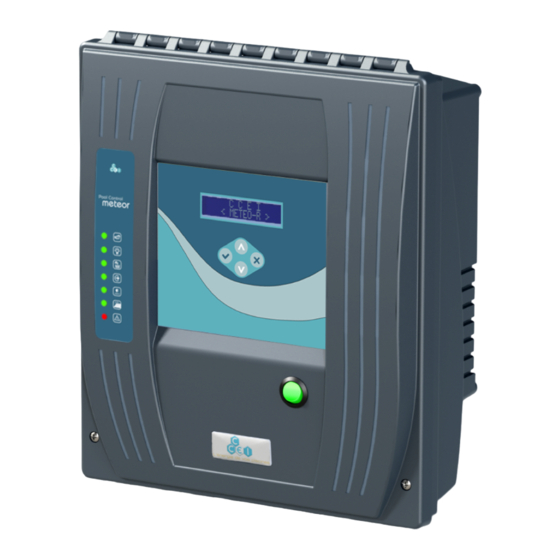
3.1. Presentation of the MeteoR2 ...................................................................................... 4
3.2. Filtering management .................................................................................................. 5
3.3. Auxiliary outputs ........................................................................................................ 7
3.4. Cover closure management ......................................................................................... 7
3.5. Lighting management .................................................................................................. 8
3.6. "Level regulation" Option ......................................................................................... 10
3.7. "Zen'iT" option (remote control) ............................................................................... 10
3.8. "Extra inputs" Option ................................................................................................ 11
3.9. Electric protection - Power supply ............................................................................ 11
4. Installation ........................................................................................................................... 12
4.1. Control box mounting ............................................................................................... 12
4.2. Remote control holder installation ............................................................................. 12
4.3. Temperature sensor ................................................................................................... 12
4.4. Connection to electricity ........................................................................................... 13
5. Operation ............................................................................................................................. 21
5.1. Interface presentation ................................................................................................ 21
5.2. Use ............................................................................................................................ 23
5.3. Radio-frequency remote control - use ....................................................................... 37
5.4. Supervisor menus ...................................................................................................... 39
6. Start up ................................................................................................................................ 44
A. Internal wiring diagram ................................................................................................... 45
B. Menu synopsis .................................................................................................................... 46
C. Declaration of conformity ................................................................................................. 48
Read these instructions carefully before installing, commissioning and using
this product.
MPNT0078 v3.2EN (09/03/2017)
Technical information sheet
MeteoR2
Multifunction swim-
ming pool control box
Réf : PF10Y500 / PF10Y501
Advertisement
Table of Contents

Subscribe to Our Youtube Channel
Related Manuals for ccei MeteoR2

Summary of Contents for ccei MeteoR2
-
Page 1: Table Of Contents
Table of Contents 1. Pack contents ......................... 3 2. Technical specifications ......................3 3. Description ..........................4 3.1. Presentation of the MeteoR2 ..................4 3.2. Filtering management ....................5 3.3. Auxiliary outputs ......................7 3.4. Cover closure management ..................7 3.5. - Page 2 Technical information MeteoR2 v3.2EN sheet www.c- cei.fr...
-
Page 3: Pack Contents
MeteoR2 v3.2EN sheet 1. Pack contents • 1 multifunction control box MeteoR2 • 1 temperature sensor with Ø50mm ½" fixing collar • 1 "BRiO®" 4 way radio-frequency remote control • 1 bag containing – 6 screws and 6 wall plugs (power supply box + wall mount for the remote control) –... -
Page 4: Description
3. Description 3.1. Presentation of the MeteoR2 The new generation of MeteoR2 control box retains the ease of use and installation of the first MeteoR while bringing new features designed to allow the end user to control the pool more easily. -
Page 5: Filtering Management
3.2. Filtering management It is possible for the MeteoR2 to calculate ideal filtering time every day (AUTO mode) by simply choosing the start-up time. If you prefer to control the pump operating times, it is also possible (in PROG mode) to programme 3 fixed filtering time slots (= clock). - Page 6 3.2.2. Filtering heat regulation (AUTO mode) As water temperature varies during the season, filtering times must be adjusted. This daily pump operation adjustment depending on the temperature is carried out automatically by the MeteoR2 in AUTO filtering mode. Heat regulated filtering calculation method: •...
-
Page 7: Auxiliary Outputs
When the auxiliary is configured for "Treatment", it also possible to have an "Auto" mode: In which case the daily operating time is calculated automatically by the MeteoR2. The second auxiliary output is on the electric socket located on the side of the MeteoR2. It can be coupled to the filter pump or not. -
Page 8: Lighting Management
Technical information MeteoR2 v3.2EN sheet 3.5. Lighting management The MeteoR 2 can be used to control most lighting. Several operating modes are available depend- ing on whether the pool is fitted with monochrome floodlights (simple ON/OFF) or multicoloured floodlights (Micro power cuts or compatible with BRiO RC® / BRiO RC+®). - Page 9 / programmes. 3.5.1.2. RC mode All CCEI floodlights are compatible with the RC control mode. 3.5.1.3. RC+ mode All CCEI floodlights manufactured after February 2016 are compatible with the RC + control mode. Here is the list: Floodlight Reference number...
-
Page 10: Level Regulation" Option
3.6. "Level regulation" Option The MeteoR2 includes level regulation. Three kits are available as options to complete your instal- lation; • Floater only (no topping up, only low water safety) (ref SF140008). • NIV KIT (ref PF10K006/V02) for pools fitted with skimmers, it contains –... -
Page 11: Extra Inputs" Option
MeteoR2). • A 30mA ground fault protection with a cut-off power superior to the short circuit protection calibre. Control box ref. PF10Y002 is perfectly suited to guarantee the electric protection for the MeteoR2 and the equipment connected to it. www.c-... -
Page 12: Installation
Technical information MeteoR2 v3.2EN sheet 4. Installation 4.1. Control box mounting The control box is fixed to the wall using the 4 included screws and wall plugs. 4.2. Remote control holder installation The remote control holder is fixed to the wall using the 2 included screws and wall plugs. -
Page 13: Connection To Electricity
• either at 3.50 m from the pool edge. This distance takes into account the dis- tance around obstacles. If the box MeteoR2 is installed behind a wall, this will then be the distance required to complete the loop and connect to the box. - Page 14 Technical information MeteoR2 v3.2EN sheet www.c- cei.fr...
- Page 15 4.4.1. Electricity supply The connection is to the two connection terminals and the earth bar. The MeteoR2 must have a 230V single phased 50Hz power supply protected by a 30mA ground fault protection, which supplies sufficient intensity. There must also be a short-circuit protection (max. 16A) on the control box power supply line.
- Page 16 Technical information MeteoR2 v3.2EN sheet 4.4.2. Temperature sensor The temperature sensor is connected to the unpluggable terminal block located directly on the mod- ule. Pass its wire through the small cable gland provided. Use a flat tipped screwdriver of a size adapted to the terminal block! (max.
- Page 17 Technical information MeteoR2 v3.2EN sheet 4.4.4. Auxiliary 1 Auxiliary 1 (brush, heating, treatment, auxiliary 1) is connected to the second contactor (the one on the right). The electric connection differs depending on how Auxiliary 1 is used (brush, heating, treatment or auxiliary). Follow the instructions below to the letter.
- Page 18 Auxiliary 2 is the power socket on the side of the control appliance. It is a standard European 2P+E socket. The maximum power available on this socket is 1000W. There is a 5A fuse in the control box to protect this output. 4.4.6. Floodlights Depending on the MeteoR2 reference, there are 2 possible connections: PF10Y501 12V 100VA PF10Y502 12V 300VA The connection is made to a 2-point "screw"...
- Page 19 UVs and most pollutants, so the need is significantly less. Most covers are fitted with a limit switch that the MeteoR2 can be connected to so that it can adjust its operation. This contact must be open when the cover is open, and closed when the cover is over the pool.
- Page 20 Technical information MeteoR2 v3.2EN sheet 4.4.9. Level regulation The floater (or channel for overflow pools) is connected to the unpluggable terminal block located directly on the module. Pass its wire through a supplied cable gland. The top-up solenoid is connected to the lugs at the bottom right of the module. The kit includes two wires with female lugs, as well as cable glands and a round fuse to be installed next to it.
-
Page 21: Operation
Technical information MeteoR2 v3.2EN sheet 5. Operation 5.1. Interface presentation The interface has a multi-function liquid crystal display with two 16 character lines, 4 keys and 7 status indicators; Component Description "UP / PLUS" Used to increment values or to scroll to the top of setting or programme lists "DOWN / MINUS"... - Page 22 Technical information MeteoR2 v3.2EN sheet Component Description Indicator lamp FILTERING output active. Indicator lamp LIGHTING output active. Indicator lamp TOP-UP output active. AUXILIARY 1 output active. (Auxiliary, Treatment, Heating or Booster Indicator lamp pump depending on the configuration). Indicator lamp AUXILIARY 2 output active.
-
Page 23: Use
Technical information MeteoR2 v3.2EN sheet 5.2. Use The system is switched on using the luminous switch on the front. The screen displays the following home message: Meteor-2 Pool Controller followed by the display of: Display No To scroll through the menus, use the... - Page 24 Technical information MeteoR2 v3.2EN sheet 5.2.1. System status The default screen (screen saver) gives information on the MeteoR2 function statuses by alternating between filtering and auxiliary function messages; On the left is the water temperature, and on the right 25.0°C 10:10 the current time.
- Page 25 Technical information MeteoR2 v3.2EN sheet Depending on the system status, the following symbols are shown on the screen; Symbol Meaning Topping up in progress The "top-up solenoid" output is activated. Output active. (Filtering, Aux1, Aux2 depending on the displayed screen) Freeze protection active.
- Page 26 5.2.2. Messages Alternating with the status screen (screen saver) described above, the MeteoR2 gives the user in- formation to help prevent possible anomalies or to troubleshoot a possible fault. Messages are then displayed alternating with the device status:...
- Page 27 Technical information MeteoR2 v3.2EN sheet 5.2.3. Menus Using the keys, it is possible to scroll through the screens to access the following menus; Screen Function CONFIGURATION Used to access the filtering function settings. MENU CONFIGURATION Used to access the lighting function settings.
- Page 28 Technical information MeteoR2 v3.2EN sheet Screen Function • Treatment / Auxiliary / Booster pump : This screen dis- plays its operating mode (Off/On/Prog + Auto if treat- ment) alternating with the programmed times if the mode is PROG or AUTO. An "arrow" symbol is displayed if the Prog ->...
- Page 29 Technical information MeteoR2 v3.2EN sheet 5.2.4. Graphic clock A graphic clock is used to show the filter pump operating time slots. The first line (AM) is for the morning, the second (PM) for the afternoon. Each half-day is split into twelve hours, each character representing an hour.
- Page 30 Technical information MeteoR2 v3.2EN sheet 5.2.5. FILTERING MENU This menu gives access to the filtering function settings. Screen Function MENU Use to select the filtering mode (see below). AUTO Used to enter the times for the P1 filtering time slot.
- Page 31 The different possible filtering modes are the following: • OFF: Filtering is not controlled by the MeteoR2. • ON: Filtering is in override mode, 24h/24h • PROG: Filtering will be triggered using the settings for the 3 filtering time slots P1 to P3.
- Page 32 Technical information MeteoR2 v3.2EN sheet 5.2.6. LIGHTING MENU This menu gives access to the lighting function settings. Screen Function • OFF: Lighting is off • ON: Lighting is on 24 hours per day. MENU • PROG: Lighting will be triggered depending on the time slot settings below.
- Page 33 Technical information MeteoR2 v3.2EN sheet 5.2.7. AUXILIARY MENU This menu gives access to the auxiliary function settings. Depending on the selected operating mode for the auxiliary output, the name of this menu changes (Auxiliary / Treatment / Heating / Booster pump).
- Page 34 TREATMENT mode (see supervisor menu). As water temperature varies during the season, treatment times must be adjusted. This daily treat- ment output adjustment depending on the temperature is carried out automatically by the MeteoR2 in AUTO treatment mode. The calculation is only made during the operating time slots (visible on the Treatment status screen).
- Page 35 Technical information MeteoR2 v3.2EN sheet Example of calculated treatment time in AUTO mode; Pool water 10°C 15°C temperature Time in AUTO mode / PT = 10h 07:30 8h to 18:00 Time in AUTO mode / PT = 14h 11:30 8h to 22:00 Time in AUTO 0h30 (min.
- Page 36 Technical information MeteoR2 v3.2EN sheet 5.2.8. CONFIGURATION MENU This menu gives access to the device's general settings. Screen Function Clock setting Used to set the time on the device. 10:10 Date setting Used to set the date on the device.
-
Page 37: Radio-Frequency Remote Control - Use
Technical information MeteoR2 v3.2EN sheet 5.3. Radio-frequency remote control - use The radio-frequency remote control can be used to control colour changes from a distance. A wall mount is also supplied. This mount is attached to a wall using two screws, it holds the emitter when not in use. - Page 38 Technical information MeteoR2 v3.2EN sheet 5.3.1. Reinitialisation If you have several floodlights that do not run synchronously or light in different colours, it may be useful to reinitialise them. To do this, in addition to the method method described in the “stand- alone”...
-
Page 39: Supervisor Menus
Technical information MeteoR2 v3.2EN sheet 5.4. Supervisor menus 5.4.1. Access to the Supervisor menus Some of the functions on the device are reserved for use by installers or the persons in charge of maintaining the device. To access the supervisor menus, 1. - Page 40 • T. Switch: Used to control most colour changes using mi- cro power cuts (Toggle Switch). Brio RC+ • Brio RC: Used to control CCEI lighting compatible with BRIO RC. • Brio RC+: Used to control CCEI lighting compatible with BRIO RC+.
- Page 41 Technical information MeteoR2 v3.2EN sheet Screen Function • Heat. : Heating • Boost. : Booster pump Heating/ Frost If auxiliary 1 is configured as HEATING mode, this screen is used to activate it when the control box is in freeze protection Yes / No mode.
- Page 42 Technical information MeteoR2 v3.2EN sheet Screen Function This screen is used to configure the type of pump current monitoring; Pump protection • None: No pump current monitoring. • > Imax: Only excess intensity is monitored. <Imin >Imax • < Imin: Only under intensity is monitored.
- Page 43 Technical information MeteoR2 v3.2EN sheet 5.4.4. Remote control code There are 10 switches inside the remote control unit (under the battery cover) which are used to set the code. The code displayed on the "Remote control" menu must correspond to the positions of switches n °5 to 8.
-
Page 44: Start Up
6. Start up Once the electric connections have been made, you must configure your MeteoR2. 1. Go to the supervisor menu 2. Set the options depending on the installation configuration • Type of auxiliary 1 (Auxiliary, Heating, Booster pump or Treatment) •... -
Page 45: Internal Wiring Diagram
Technical information MeteoR2 v3.2EN sheet A. Internal wiring diagram www.c- cei.fr... -
Page 46: Menu Synopsis
Technical information MeteoR2 v3.2EN sheet B. Menu synopsis MENUS METEOR2 ind. B English METEOR2 26/05/2016 Meteor-2 Display Nr Pool Controller 25°C 10:10 25°C 10:10 Filtr. Program. Auxil. Program. MENU FILTRATION FILTRATION AUTO Off/On/Prog/Auto Filtration P1 10:00 => 18:00 Filtration P2 22:00 =>... - Page 47 Technical information MeteoR2 v3.2EN sheet MENUS METEOR2 ind. B English METEOR2 26/05/2016 Type of Light Brio RC+ Mono/T.Switch/Brio RC/Brio RC+ Aux 1 Function Auxil. Auxil./Treatmnt/Heating/Booster Heating/Frost Yes/No Aux 1 controlled Yes/No Level control Fill None/Fill/Overflow/Safety DST Auto Yes/No Aux 2 controlled...
-
Page 48: Declaration Of Conformity
Technical information MeteoR2 v3.2EN sheet C. Declaration of conformity Bleu Electrique SAS (FR47403521693) declares that product Me- teoR2 is compliant with the safety and electromagnetic compatibili- ty requirements of European directives 2006/95/CE and 2004/108/CE. Emmanuel Baret Marseille, on 09/03/2017 Distributor's stamp Date of sale: .
Need help?
Do you have a question about the MeteoR2 and is the answer not in the manual?
Questions and answers