Table of Contents
Advertisement
Quick Links
Advertisement
Table of Contents

Summary of Contents for Smartwave SmarTire
- Page 1 SmarTire Tire Pressure Monitor Tool Users Manual 090.0011...
-
Page 2: Table Of Contents
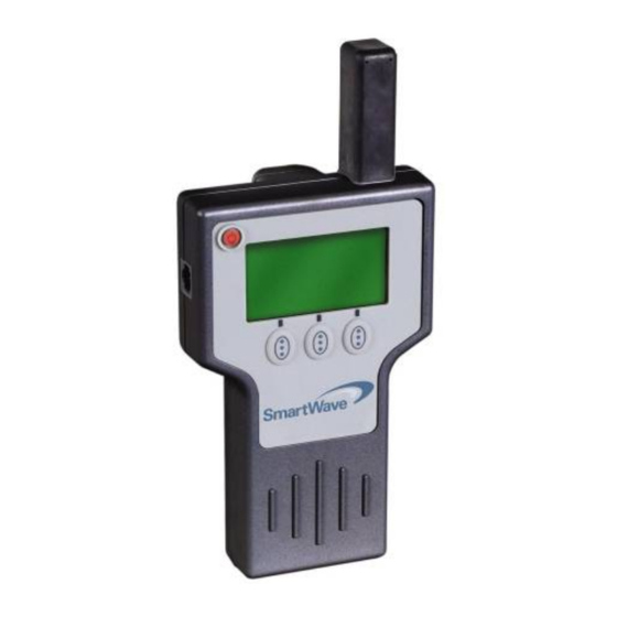
FCC Compliance Label The FCC compliance label is located on the back of the tool as shown in figure 1. Table of Contents FCC Compliance Label .................2 User Interface Illustration ..............2 Introduction....................3 Tire Rotation...................3 Testing Tire Sensors ................4 Main Menu ....................5 Main Menu Icon Legend................6 Main Menu Details .................7 Initiate Function .................... -
Page 3: Introduction
Introduction Testing Tire Sensors The sensor test procedure is used to verify the sensors can transmit The tire pressure monitoring system consists of a tire pressure sensor valid data after they have been activated with a Low Frequency (LF) inside the wheel that will transmit a radio frequency (RF) signal that transmission from the tool. -
Page 4: Main Menu
Main Menu Main Menu Icon Legend STATE DESCRIPTION ICON These icons indicate the battery life of the handheld device at startup. This icon is located in the lower left Handheld area of the tool display. Battery Life To continue, press the Check mark. To turn off the tool and replace the batteries, press the X. -
Page 5: Main Menu Details
Main Menu Details Set-up Menu Icon Legend Initiate Function Selecting the Setup button commands the tool into Setup mode. If the Initiate button is pressed, the tool will retrieve sensor ID, pressure STATE DESCRIPTION ICON data and battery status from the sensor that is displayed •... -
Page 6: Set-Up Menu Icon Explanations
Maintenance Tool software update program Set-up Menu Icon Explanations Software Update The software update function is used to download the latest SmartWave Maintenance Tool software from a personal computer. Refer to update information supplied with future software updates. Maintenance Tool Software Update The maintenance tool function allows the user to easily upgrade the software in the field. -
Page 7: Measurement Units
5. Activate each of the vehicle's wheel sensors in the proper order (see service information for the activation order). 6. Hold the SmartWave tool’s antenna against the tire’s upper sidewall Stored Sensor Information Retrieval in line with the valve stem. Press the Learn button . -
Page 8: Walk-Around Learn Download
Scroll down the Menu and set the maintenance tool to Learn Ambient Pressure. J1939 Receiver SmartWave J1939 receiver with RS232 connection. Activate ambient sensor using the Learn function. The ID of the ambient sensor to be used for compensating the ambient pressure appears on the maintenance tool display. -
Page 9: Sensor Learn
Execution Icons Sensor Learn STATE DESCRIPTION ICON The following is displayed after activating a sensor within sensor LF range pressing the Learn button. Confirm Good Cancel Cancels current action. Information Received From Sensor After Activating Learn Back Back, Select, Enter, Return to main menu. Scroll Scroll displayed data or selection. -
Page 10: Application Notes, Display Examples
Application Notes, Display Examples Sensor Initiation The following are possible scenarios after activating a sensor within LF sensor range using the Initiate command. The received information by the maintenance tool is stored in the tool memory and can be recalled by selecting the Sensor Information Storage command in the menu settings. -
Page 11: Specifications
Note: Transmission/communication of SmartWave tire sensor at a maximum distance of 12 inches. Three “C” Cell Batteries Supply Voltage (Alkaline or NiMH) Or equivalent NiMH rechargeable. Antenna Types • The SmarTire tool has an internal antenna for communicating with SmartWave sensors. -
Page 12: Mechanical Specifications
Mechanical Specifications PARAMETERS CONDITION VALUE UNITS Weight Without batteries Injection Housing Material molded plastic enclosure Troubleshooting The tool does not power up or Replace batteries. turns off when the Activate button is pressed. No tire pressure sensor data Make sure the Activate Antenna is held is received. - Page 13 090.0011...
Need help?
Do you have a question about the SmarTire and is the answer not in the manual?
Questions and answers