
Related Manuals for General Air Products NGP-1000D-M2


Summary of Contents for General Air Products NGP-1000D-M2
- Page 1 Nitrogen Generator NGP-1000D-M2/M3 Installation, Operation and Maintenance Manual 1 800 345 8207 Call or visit our web site for our complete product listing www.GeneralAirProducts.com 216442 REV: 2 (7/18)
- Page 2 1-800-345-8207...
-
Page 3: Table Of Contents
Table of Contents Safety & Warnings ............. . . Section 1 System Overview . -
Page 4: Safety & Warnings
Only competent personnel, who have been trained, qualified, and approved by General Air Products should perform commissioning, servicing, and repair procedures. When handling, installing, or operating this equipment, personnel must employ safe engineering practices and observe all related local regulations, health, and safety procedures, and legal requirements for safety. - Page 5 The warnings in this manual cover the most known potential hazards, but by definition cannot be all-inclusive. If the user em- ploys an operating procedure, item of equipment, or a method of working that is not specifically recommended by General Air Products, the user must ensure that the equipment will not be damaged or become hazardous to persons or property.
-
Page 6: System Overview
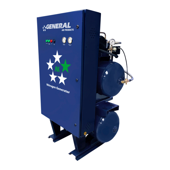
Section 2 - System Overview The Nitrogen Generator operates using membrane technology. The smaller oxygen and water vapor molecules can pass through (permeate) the membrane quickly. The larger nitrogen molecules are less likely to diffuse through the separator tubes; therefore, they continue downstream to the separator outlet. The permeated molecules are discharged to the atmos- phere through a vent in the separator casing. - Page 7 Figure 2: Typical NGP-1000D-M2/M3 External View 1-800-345-8207...
- Page 8 Figure 3: Typical NGP-1000D-M2/M3 Internal View 1. Nitrogen Membrane 9. Coalescing Filter 2. Nitrogen Control Panel 10. Separator 3. Filter Drain Solenoid Test 11. Clean Out Valve on Strainer 4. Bypass Valve (Yellow Handle) 12. Nitrogen Solenoid Valve 5. Nitrogen Tank Pressure Switch 13.
- Page 9 Rapid release of nitrogen gas into an enclosed space displaces the oxygen and can cause an asphyxiation hazard. Inhalation of nitrogen in excessive concentrations can result in unconsciousness without any warning symptoms. Run a dedicated electrical circuit with an electrical disconnect switch to sprinkler room. Model Phase Amperage Voltage NGP-1000D-M2-2A SINGLE 11.6 208v NGP-1000D-M2-3A SINGLE 230v...
-
Page 10: Uncrating And Inspection
Section 4 - Uncrating and Inspection On arrival, do a full inspection by checking all packages and crates in the shipment for damage. If damage is found, sign for the damage or refuse the shipment. Contact the carrier immediately and file a shipping damage claim with the carrier. -
Page 11: Installation Of Nitrogen Generator
Section 5 - Installation of Nitrogen Generator Anchor the unit to a level surface using the ½” diameter holes on the floor mounting brackets. It is recommended practice to use the vibration isolation kit to prevent excess vibration. Install a ½” ball valve at the nitrogen storage tank outlet connection. -
Page 12: Wiring
Section 6 - Wiring of NGP-1000D-M2/M3 Wire the NGP-1000D-M2/M3. All wiring should be performed by a licensed electrician and conform to NEC and all applicable local standards. For wiring instructions refer to the Wiring Diagram. Wiring location is in the nitrogen cabinet. See Figure 6. -
Page 13: Standard Air Filling Method
Section 7 - Standard Air Filling Method Before beginning, make sure the water supply to the sprinkler system is turned off. Make sure all piping connections have been made according to installation instructions. Close all Air Maintenance Device valves. If multiple AMDs are used, ensure all valves are in closed position. - Page 14 Power the nitrogen generator system ON. The Power On light and the Nitrogen Solenoid light should turn green. See Figure 9 The nitrogen storage tank will fill to 75±3 PSI, then the nitrogen solenoid will close. The Nitrogen Solenoid light should now be off.
- Page 15 The nitrogen generator is now ready to fill the fire sprinkler system to the desired supervisory pressure. Open the ball valve at the nitrogen storage tank outlet. Open the Air Maintenance Device bypass valve to begin filling the sprinkler system. See Figure 13. CAUTION If there is more than one AMD on the system, then close the others.
-
Page 16: Nitrogen Filling Procedure
Section 8 - Nitrogen Filling Procedure Once the system is at the desired supervisory pressure, it is time to start injecting nitrogen. Close the Bypass Valve (Yellow Handle). Open the Nitrogen "Inlet" Valve (Blue Handle). Open the Nitrogen "Outlet" Valve (Blue Handle). Figure 15 Bypass Valve 1-800-345-8207... - Page 17 85 and 105 PSI. See Figure 17. Record the time it takes for the nitrogen storage tank to reach 75 PSI. It should typically take 14 minutes for the NGP-1000D-M2, and 8 minutes for the NGP-1000D-M3. NOTE: The air compressor will cycle on and off during this process.
- Page 18 When the nitrogen storage tank pressure reaches 75±3 PSI, the Nitrogen Solenoid light will turn OFF and the nitrogen membrane pressure will go to zero (0). See Figure 18. Repeat steps 5-8 a second time to ensure nitrogen storage tank fill up times are consistent. On the second cycle, open the Nitrogen Test Port Valve (Green Handle) located on the inside of the cabinet.
-
Page 19: Nitrogen Control Module
Section 9 - Nitrogen Control Module The Nitrogen Control Module is a built in PLC used to control the nitrogen generator and provide useful information on alarms, compressor operating hours, cycles and nitrogen solenoid operation. Normal operation does not require any operator input. The display should read “Nitrogen Generator Normal”... -
Page 20: Alarms/Troubleshooting
Section 10 - Nitrogen Generator Alarms/Troubleshooting The nitrogen generator has 7 alarms. If an alarm is activated, the alarm light will turn red on the outside of the cabinet and the Alarm Horn will sound. The alarm number will also display on the Nitrogen Control Module inside the cabinet. To clear alarms, cycle power or press ALT then hold the right arrow key for 5 seconds. - Page 21 Alarm 6 – Compressor Excess Cycles Issue: Air compressor has cycled more than 36 times in 3 hours. Answer: The unit is running more frequently than normal. Check to ensure all valves in the cabinet are in correct position. Check the nitrogen generator system for leaks. Check the sprinkler system for leaks.
-
Page 22: Nitrogen Generator Leak Check Method
Once the air compressor and Nitrogen Solenoid light have both turned off, record the pressure on the air storage tank and the nitrogen storage tank. This should typically take 7 minutes for the NGP-1000D-M2/M3. Let the nitrogen generator sit for 30 minutes. The air compressor or the Nitrogen Solenoid light should NOT turn on during this time. -
Page 23: Air Side Leak Check Method
Allow the pressure to build to 105±3 PSI. Make note the time it takes to reach this pressure. This should typically take less than 5 minutes for the NGP-1000D-M2/M3. If the unit reaches 105±3 PSI and does not stop, this could indicate a pressure switch issue. -
Page 24: Nitrogen Membrane Check
Quickly close the petcock. Record the time it takes for the Nitrogen Solenoid light to turn off. This should typically take 14 minutes for the NGP-1000D-M2 and 8 minutes for the NGP-1000D-M3. Check the membrane pressure gauge, it should be between 85-105 PSI. -
Page 25: Maintenance
Section 15 - Maintenance WARNING All pressure must be relieved from the entire nitrogen generator system BEFORE servicing. To avoid system damage and/or personal injury, the nitrogen generator should be isolated from the compressed air supply and the generator systemfully depressurized before any maintenance or service is performed. - Page 26 Filter Replacement To replace the filters in the generator cabinet: Isolate the nitrogen generator and relieve pressure. Disconnect the power to the nitrogen generator. Disconnect drain hose from bottom of filters. Unscrew the bowl from the filter body. See Figure 23. Remove the element by unscrewing the filter.
-
Page 27: Normal Operating Parameters
Section 16 - Normal Operating Parameters The Nitrogen Generator System uses a two tank system design to deliver high purity nitrogen to the fire protection system.The pressure switch on the air storage tank controls the air compressor by turning it on and off at the desired pressure set points. -
Page 28: Nitrogen Analyzer Instructions
Section 17 - Nitrogen Analyzer Instructions Component Description necessary. normal operation. Automatic Calibration After the unit is turned on, it will automatically calibrate to room air. The display should be stable and reading 79.1%. To check the nitrogen concentration of a sample gas: (after the unit has been calibrated) Connect the Tygon tubing to the bottom of the analyzer by threading the barbed adapter onto the oxygen sensor. - Page 29 Code Meaning Corrective Action E02 or ED4 CAL Err St: O CAL Err lo Sensor voltage too low CAL Err Bat Changing the Batteries When the batteries need to be changed, the device will indicate this in one of two ways: The battery icon on the bottom of the display will begin to flash.
- Page 30 Changing the Oxygen Sensor Should the oxygen sensor require changing, the device will indicate this by presenting “Cal Err lo” on the display after initiating a calibration. To change the oxygen sensor, begin by removing the three screws from the back of the device. A #1 Phillips screwdriver is required to remove these screws.
-
Page 31: Wiring Diagrams
Section 18 - Wiring Diagrams 1-800-345-8207... - Page 32 DISCONNECT SWITCH, BRANCH CIRCUIT PROTECTION AND/OR OVERLOAD RELAY TO BE PROVIDED BY INSTALLER (SEE MANUAL FOR SIZING) CR-1 OL-1 COMPRESSOR MOTOR CONTACTOR OVERLOADS NOTE 2 208-230/460V, 3 PH, 60 HZ 24 VDC POWER SUPPLY PWR-1 CONTROL POWER LIGHT LT-1 NOTE 2 NOTE 2 OVERLOAD OL-1 COMPRESSOR...
-
Page 33: Technical Specifications And Drawings
Section 19 - Technical Specifications and Drawings Size (HxWxD) 62” x 44” x 33” Size (HxWxD) 62” x 44” x 33” Weight 550 lbs Weight 550 lbs Available in 208V (11.6A), 230V (11A), single Available in 208V (11.6A), 230V (11A), single Power Supply phase and 208V (9.2A), 230V (9.2A), 460V Power Supply... -
Page 34: Warranty Policy
Company, transportation prepaid by Purchaser, areas. While General Air Products, Inc. attempts to assure that its to establish a claim under this warranty. products comply with such codes, it cannot guarantee compliance, and cannot be responsible for how the product is installed or used.
Need help?
Do you have a question about the NGP-1000D-M2 and is the answer not in the manual?
Questions and answers