Table of Contents
Advertisement
Quick Links
Manual for all flexible level sensors and wire sensors delivered be-
fore October 15th 2021
Covers: HBLT & HBSLT
Wire sensor suited for liquids like NH3, and HFC/HFO refrigerants
•
Flex sensor suited for liquids like CO2 and Hydro carbons
•
Can be used in refrigeration systems and similar demanding systems.
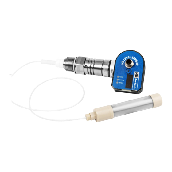
Introduction
Wire and Flex are intelligent liquid level sensors which can be installed in a vessel or in a standpipe. For the Wire sensor the
sensor element is a stainless steel wire insulated with PTFE and for the Flex sensor the element is a stainless steel wire
mounted with steel tube elements to increase the sensitivity. Both sensors can to be mounted directly in a stand pipe. If they
need to be installed in a vessel they need an inner pipe. Both sensors measure between the wire/tube elements and the sur-
rounding pipe.
The sensor can be installed in refrigeration systems and similar demanding applications with high pressures and aggressive
fluids. The sensor emits a 4-20mA analog signal, which is proportional to the liquid level.
Wire and Flex level sensor manual 04
ATEX/Ex versions included
October 2021 HBproducts.dk
1
Advertisement
Table of Contents

Summary of Contents for HB HBLC-Fgas
-
Page 1: Introduction
Manual for all flexible level sensors and wire sensors delivered be- fore October 15th 2021 Covers: HBLT & HBSLT Wire sensor suited for liquids like NH3, and HFC/HFO refrigerants • Flex sensor suited for liquids like CO2 and Hydro carbons •... -
Page 2: Table Of Contents
If changes are made to type-approved equipment, this type approval becomes void. The product's input and output, as well as its accessories, may only be connected as shown in this guide. HB Products assumes no responsibility for damages re- sulting from not adhering to the above. -
Page 3: Application Examples
Installation Instructions—wire sensor The wire sensor is designed for level measurement of liquids in vessels like, tanks, pump separators and receivers . The sensor can be mounted in a standpipe from 1” (25mm) up to 4” (100mm) diameter or directly in a vessel with an inner pipe from 1”... - Page 4 Stand pipe: DN32..…DN65. Recommended pipe standard: DIN 10220 Recommended bending: DIN 2615-1/Type 3 Recommended TEE: DIN 2615-1 Standpipe: DN65…DN100. Recommended pipe standard: DIN 10220 Recommended bending: DIN 2615-1/Type 3 Site pipe can be designed in smaller pipe e.g. o.5 x DN. Wire and Flex level sensor manual 04 October 2021 HBproducts.dk...
- Page 5 Installation Instructions—Flex sensor The Flex sensor is designed for level measurement of liquids in vessels like, tanks, pump separators and receivers . The sensor can be mounted in a standpipe 1” (25mm) or 1 ¼” (32mm) diam- eter or directly in a vessel with an inner pipe 1” (25mm) or 1 ¼”...
-
Page 6: Installation Wire
Wire adjustment—Wire sensor The sensor is installed in the standpipe or directly in the tank. The sensor length is determined by standpipe length or tank height. Cut the insulated steel wire to desired length with a wire cutters or bolt cutter in the end where the weight is in- stalled. -
Page 7: Installation Flex
Installation instruction—Flex sensor The sensor can be shortened to fit the standpipe length or vessel height. The sensor consist of a 5 mm steel wire fitted with a stainless steel weight at the bottom, plastic spacers and aluminum pipes. The purpose of the plastic spacers is to keep the metal parts away from the pipe and the aluminum pipe increase the sensitivity of the sensor. -
Page 8: Connection Diagrams
How to connect the sensor Two different type of sensors • A pure sensor version with 4-20 mA output • A controller version with both cable for direct valve control and analog output All sensors can provide a signal for a PLC via the M12 connection. The M12 connection is also used for power supply. Some versions are able to control a valve directly. - Page 9 Connection diagram for sensors with control ca- Suited for • HBSLT/S and HBSLT–wire & Flex/S ble for all common stepper motor valves — here • HBSLC/S shown with Carel E2V +24V DC or AC - Common AI Remote set point 4-20 mA AO, 4-20 mA level Run in signal The sensor has a build in controller for a stepper valve.
- Page 10 Connection diagram for sensors with control ca- Suited for ble for pulse modulating valve — here shown • HBSLT/PWM and HBSLT–wire & Flex/ with Danfoss AKV/AKVA • HBSLC/PWM +24V DC or AC - Common AI Remote set point 4-20 mA AO, 4-20 mA level Run in signal The sensor has a build in controller for a pulse modulating valve.
- Page 11 Connection diagram for sensors with control ca- Suited for • HBSLT/C and HBSLT–wire & Flex/C ble for modulating valve — here shown with Sie- • HBLC/C mens MVS661 MVS661 motor valve -common - = White common + supply + = Brown Supply mA input AO = Grey , 4-20 mA mA output position...
-
Page 12: Analog Output
HB-tool. It is also possible to make the offset by making a calibrations to known levels also in the tool. -
Page 13: Use The Hb-Tool For Setting Up The Sensor
Select Control/Level to select the mode Setting up the sensor The HB tool has three pages of settings. Some fields will be shown in grey when they are not relevant/ active with the setting chosen. Detailed explanations of the individual fields will show up when the mouse is moved over the field. - Page 14 Basic settings Filter time averages the output over a peri- Here you make the primary settings of the sensor od and reduce fluctua- tions Here you set the parame- ters for the control func- Here you set the pa- tion. rameters for the sen- When “Run in signal”...
- Page 15 Advanced settings Here you make the advanced settings of the sensor Here you set the parame- ters for the alarm func- tion. Only available for sensors without cable Here you can adjust parameters for the valve control Alarm relay function: Here, the relay function is indicated, depending upon the instructions –...
- Page 16 Diagnostic (calibration of sensor) Here you make the calibration of the sensor. If the sensor is operating in one of the predefined liquid it is delivered with a calibration and does normally not need further calibration. If you need higher accuracy the sensor can be calibrated Here you can see and change the zero Here you can see and change the SPAN calibration.
-
Page 17: Led Indication
LED indication • Green LED indicates 24 V DC supply; it flashes during operation. If "run-in" is not used, this function must be deactivated in the tool. • Yellow LED indicates control. The flashing sequence indicates if the valve is closing or opening. •... -
Page 18: Fault Detection
Please contact your local distributor about how to handle complaints. Further Information For further information, please visit our website, www.hbproducts.dk, or send an email to: support@hbproducts.dk. HB Products A/S – Bøgekildevej 21 – DK8361 Hasselager – support@hbproducts.dk – www.hbproducts.dk Wire and Flex level sensor manual 04... - Page 19 Wire and Flex level sensor manual 04 October 2021 HBproducts.dk...
- Page 20 You need a computer and a USB/M12 cable to do the calibration and more advanced setup. The setup is done in the HB-tool which is down- loaded from the HBproduct web page www.hbproducts.dk...
Need help?
Do you have a question about the HBLC-Fgas and is the answer not in the manual?
Questions and answers