Table of Contents
Advertisement
Quick Links
Advertisement
Table of Contents

Related Manuals for Iwatsu CS-5000 Series


Summary of Contents for Iwatsu CS-5000 Series
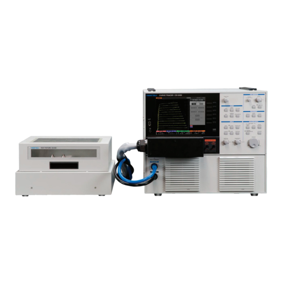
- Page 1 Instruction Manual Curve Tracer CS-5000 series CS-5100 CS-5200 CS-5300 CS-5400...
- Page 2 Ⓒ 2013 IWATSU ELECTRIC CO., LTD. All rights reserved....
- Page 3 Reproduction or reprinting of the contents of this manual without prior permission from Iwatsu is prohibited. For questions about this instrument, contact IWATSU listed at the end of this manual or our sales distributors. Manual Part Number KML112431 ...
- Page 4 Read this page to ensure proper safety. (Also read the following pages.) WARNING ● In measurement with this instrument, high voltage may be applied and high current may be supplied. Always close the cover before measurement after setting the DUT (Device under test) on the test fixture.
- Page 5 Continued use under these circumstances may result in electric shock or fire. After taking measures above, contact Iwatsu office or our sales distributors for repair. Repairing the instrument yourself is very dangerous. Do not attempt to repair the instrument under any circumstances.
- Page 6 ● When handling power cord, observe items below: If not, fire or electric shock may occur. If the power cord is damaged, contact Iwatsu office or our sales distributors for repair. - Do not attempt to fabricate the power cord.
- Page 7 Iwatsu office or our sales distributors for repair. ● Do not use this instrument if it is not functioning correctly.
- Page 8 Read this page to ensure proper safety. (Also read the following pages.) CAUTION ● Set the power supply cord up in the place where it is pulled out easily. When this instrument is a dicey situation, it is necessary to cut power off promptly. Do not attempt to place this instrument in the location where difficult to remove the power supply cord from the receptacle.
- Page 9 If you do not have the proper packing material or shock absorbing material, contact Iwatsu office or our sales distributors. When having the intrument transported by a shipping company, write "Precision Instrument - Handle With Care" on each side of the packing box.
- Page 10 Long-term use of an instrument having a dirty or dusty interior may cause a fire or malfunction. It is recommended that you contact Iwatsu office or sales distributors to check and clean the interior, calibrate, etc., about once per year.
- Page 11 Items When receiving this instrument, please verify items in the package. ♦ Curve Tracer .................... : 1 Test fixture - CS-303 (for CS-5100 / CS-5200 / CS-5300) ..........: 1 set - CS-304 (for CS-5400) ................: 1 set * Either depending on CS-5400 / CS-5300 / CS-5200 or CS-5100 <Accessories>...
- Page 12 Updating version of software Since each software program has suitability to a machine, contact Iwatsu office or our sales distributors for software version update or visit on our Web site (URL : http://www.iti.iwatsu.co.jp). For the procedure of the version updating software in the main unit, refer to the section 3.11.1.6...
-
Page 13: Table Of Contents
Contents Capter1 Overview ..........................1-1 1.1 Features............................1-1 Capter2 Name and Function of Each Part (Outline) ............... 2-1 2.1 Name and outline of each part on front panel ................2-1 2.1.1 Function keys and FUNCTION knob ..................2-3 2.1.2 STEP GENERATOR ......................2-4 2.1.3 COLLECTOR SUPPLY ...................... - Page 14 3.4 Screen structure .......................... 3-17 3.5 Setting with function keys and knobs ..................3-19 3.6 Setting step generator ......................... 3-20 3.6.1 Setting STEP knob ......................3-21 3.6.2 Setting STEP 1/10 key ......................3-22 3.6.3 Setting OFFSET knob ......................3-23 3.6.4 Setting MENU key ....................... 3-24 3.7 Setting collector supply ........................
- Page 15 4.1.1 Diode measurement ......................4-2 4.1.2 Transistor measurement ..................... 4-10 4.1.3 FET measurement ....................... 4-23 4.2 Characteristics measurement ...................... 4-34 4.2.1 IGBT characteristics measurement ..................4-34 Capter5 Daily Maintenance and Calibration ................... 5-1 5.1 Daily maintenance ......................... 5-1 5.2 Calibration............................5-3 5.3 Repair and sending of repaired product ..................
- Page 16 Memo...
-
Page 17: Capter1 Overview
Importance of evaluating power semiconductor devices is increasing to improve the efficiency in use of energy. The Curve Tracer CS-5000 series have been improved further for the power of CS-3000 and have been developed to evaluate power semiconductor devices in such a power electronics market. - Page 18 Capter1 Overview ■ Remote control function CS-5000 series supports LAN interface (10 Base-T/100 Base-TX Ethernet). External connection uses LAN terminal on the rear panel. For details; e.g., usage and commands, see Remote Control Manual recorded in the attached CD. Curve Tracer CS-5000 Series Instruction Manual...
-
Page 19: Capter2 Name And Function Of Each Part (Outline)
HIGH CURRENT compared with CS-5400. CS-5200/CS-5300 have part ⑧ HIGH CURRENT, but don't have ⑨ HIGH CURRENT high current connector. ① ③ ② ⑤ ④ ⑦ ③ ① ② ⑧ ④ ⑦ ⑥ Figure 2.2 Front panel of CS-5200/CS-5300 Figure 2.3 Front panel of CS-5100 Curve Tracer CS-5000 Series Instruction Manual... - Page 20 Included in CS-5200/5300/5400. (Not included in CS-5100.) HIGH CURRENT ⑧ Included in only CS-5400. (Not included in CS-5100/5200/5300.) HIGH CURRENT ⑨ The HC cable of the test fixture CS-304 is connected with the HIGH Connector terminal CURRENT connector terminal. Curve Tracer CS-5000 Series Instruction Manual...
-
Page 21: Function Keys And Function Knob
LCD when the function menu is selected. It is available only when icon appears on the submenu. Pushing FUNCTION knob allows transfer among base steps and switchover of a side to be moved during cursor measurement. Curve Tracer CS-5000 Series Instruction Manual... -
Page 22: Step Generator
It displays the 1st page menu. OFFSET MODE It changes the offset mode; i.e., offset is added to the entire Section pulse steps or each pulse step. It is available when STEP is 3.6.4.2 set to PULSE. Curve Tracer CS-5000 Series Instruction Manual... -
Page 23: Collector Supply
GENARATOR is set to PULSE.) SWEEP TYPE It sets SWEEP direction. SWEEP END VARIABLE It sets the voltage for SWEEP, using the ratio (%) to MAX PEAK VOLTAGE. Validity / invalidity changes by setting SWEEP TYPE. Curve Tracer CS-5000 Series Instruction Manual... - Page 24 When using the software looping, the lamp turns on (other than 0%). It sets items below on LOOPING-COMPENSATION menu: It sets the numeric value of setting range (%). HARDWARE COMPENSATION It sets the numeric value of setting range (%). SOFTWARE COMPENSATION Curve Tracer CS-5000 Series Instruction Manual...
-
Page 25: Measurement
VARIABLE setting value and 0% is used for measurement. For step generator SWEEP, SWEEP being arbitrarily set between the maximum and minimum (offset setting value) values of a step signal is used for measurement. Curve Tracer CS-5000 Series Instruction Manual... -
Page 26: Display
It sets the horizontal range (VOLTS/DIV) of the screen and the Section 3.9.1 ⑦ VOLTS/DIV source (STEP, BASE-EMITTER, and COLLECTOR). VERTICAL It sets the vertical range (CURRENT/DIV) of the screen and the Section 3.9.2 ⑧ CURRENT/DIV source (STEP, EMITTER, and COLLECTOR). Curve Tracer CS-5000 Series Instruction Manual... -
Page 27: System
It is a function to observe the characteristic of the semiconductor 3.11.7.4 COLLECTOR SWEEP DOUBLE devices such as hysteresis. SWEEP can be measured by turning continuously in the image like start point A⇒UP SWEEP⇒ turning point B⇒DOWN SWEEP⇒ start point A. Curve Tracer CS-5000 Series Instruction Manual... -
Page 28: Name And Function Of Each Part On Rear Panel
The outside air is sucked from the openings on the both sides and ② discharged from it. ETHERNET terminal LAN connector connection terminal to connect this instrument with ③ the external controller through Ethernet. Specification: 10 Base-T / 100Base-TX Ethernet 2-10 Curve Tracer CS-5000 Series Instruction Manual... -
Page 29: Test Fixture Cs-303
Case3: Connecting HIGH VOLTAGE terminal and HIGH CURRENT terminal of collector output at the same time on DUT; It may be cause for fire and/or malfunction due to high voltage applied to HIGH CURRENT terminal. Curve Tracer CS-5000 Series Instruction Manual 2-11... - Page 30 ⑰ and 1kΩ resistance. Connect it with the output terminal of ⑥ step signal instead of ⑭ when using it. ADAPTER EXCLUSIVE USE These are terminals that install the test adapter. Section 3.3 ⑰ 2-12 Curve Tracer CS-5000 Series Instruction Manual...
-
Page 31: Test Adapter Cs-500 (Blank Adapter)
It connects the emitter of a measured device or equivalent terminal. Section ⑥ 3.3.4 Note: Connect each Sense terminal of above-mentioned ④ to ⑥. Especially, if connection to SENSE terminal is not made in HIGH CURRENT mode, measurement cannot be done. Curve Tracer CS-5000 Series Instruction Manual 2-13... -
Page 32: Test Fixture Cs-304
Case3: Connecting HIGH VOLTAGE terminal and HIGH CURRENT terminal of collector output at the same time on DUT; It may be cause for fire and/or malfunction due to high voltage applied to HIGH CURRENT terminal. 2-14 Curve Tracer CS-5000 Series Instruction Manual... - Page 33 BASE/GATE 1kΩ It is connected internally through the base terminal Section 3.3 ⑯ of ⑰ and the resistance of 1kΩ. ADAPTER EXCLUSIVE USE These are terminals that install the test adapter. Section 3.3 ⑰ Curve Tracer CS-5000 Series Instruction Manual 2-15...
-
Page 34: Test Adapter Cs-501A (To Type Adapter, Option)
② or ③ of Figure 2.15 like the dotted line.) ③ ② Insulation tab ① Figure 2.15 Test adapter CS-501A (front side) Figure 2.16 Test adapter CS-501A (rear side) attached to the patch panel 2-16 Curve Tracer CS-5000 Series Instruction Manual... - Page 35 - It is not possible to measure at the same time though two kinds of devices to be measured can be installed in test adaptor CS-501A. Measure by installing one device to be measured and one insulation tab. Curve Tracer CS-5000 Series Instruction Manual 2-17...
-
Page 36: Test Adapter Cs-502 (Axial Type Adapter, Option)
The test adapter CS-502 (AXIAL type adapter) is the optional instrument and can be mounted on either of test fixtures CS-303 or CS-304. ② ① ③ Figure 2.17 Test adapter CS-502 (front side) Figure 2.18 Test adapter CS-502 (rear side) attached to the patch panel 2-18 Curve Tracer CS-5000 Series Instruction Manual... - Page 37 - Do not apply a voltage exceeding 1 kV or a current exceeding 1 A to each terminal of the test adapter (Axial type adaptor) CS-502. If 1 kV or 1 A is exceeded, test adapter or a measured device might be damaged. Curve Tracer CS-5000 Series Instruction Manual 2-19...
- Page 38 (TO-263-7 type adapter) are the optional instruments and can be mounted on either of test fixtures CS-303 or CS-304. ① ② ③ CS-503 CS-504 CS-505 Figure 2.19 Test adapter CS-503/CS-504/CS-505 (front side) Figure 2.20 Test adapter CS-503 (rear side) attached to the patch panel 2-20 Curve Tracer CS-5000 Series Instruction Manual...
- Page 39 - Do not apply a voltage exceeding 1 kV or a current exceeding 1 A to each terminal of the test adapter CS-503, CS-504 and CS-505. If 1 kV or 1 A is exceeded, test adapter or a measured device might be damaged. Curve Tracer CS-5000 Series Instruction Manual 2-21...
-
Page 40: Test Adapter Cs-506 (Surface Mount Type Adapter, Option)
The test adapter CS-506 (TO-252-5 type adapter) is the optional instrument and can be mounted on either of test fixtures CS-303 or CS-304. ① Figure 2.21 Test adapter CS-506 (front side) Figure 2.22 Test adapter CS-506 (rear side) attached to the patch panel 2-22 Curve Tracer CS-5000 Series Instruction Manual... - Page 41 - Do not apply a voltage exceeding 1 kV or a current exceeding 1 A to each terminal of the test adapter CS-506. If 1 kV or 1 A is exceeded, test adapter or a measured device might be damaged. Curve Tracer CS-5000 Series Instruction Manual 2-23...
-
Page 42: Test Adapter Cs-507/Cs-509 (Surface Mount Type Adapter, Option)
① ③ ② ④ Figure 2.23 Test adapter CS-507(front side) Figure 2.24 Test adapter CS-509(front side) ⑨ ⑧ ⑩ Figure 2.25 Test adapter CS-507 or CS-509 (rear side) attached to the patch panel 2-24 Curve Tracer CS-5000 Series Instruction Manual... - Page 43 - It is not possible to measure at the same time though two kinds of devices to be measured can be installed in test adaptor CS-507 and CS-509. Measure by installing only one device to be measured. Curve Tracer CS-5000 Series Instruction Manual 2-25...
-
Page 44: Test Adapter Cs-508 (Smd Chip Type Adapter, Option)
Emitter sense terminal respectively; It may cause for burn of SENSE RESISTER inside of the unit since the sense resister connected to output of Collector output for Kelvin sensing and may be supplied exceeded current specification. 2-26 Curve Tracer CS-5000 Series Instruction Manual... - Page 45 - Do not apply a voltage exceeding 3 kV or a current exceeding 40 A to each terminal of the test adapter CS-508. If 3 kV or 40 A is exceeded, test adapter or a measured device might be damaged. Curve Tracer CS-5000 Series Instruction Manual 2-27...
-
Page 46: Test Adapter Cs-510 (Surface Mount Type Adapter, Option)
The test adapter CS-510 (SC-62 type adapter) is the optional instrument and can be mounted on either of test fixtures CS-303 or CS-304. ① Figure 2.28 Test adapter CS-510 (front side) Figure 2.29 Test adapter CS-510 (rear side) attached to the patch panel 2-28 Curve Tracer CS-5000 Series Instruction Manual... - Page 47 - Do not apply a voltage exceeding 500 V or a current exceeding 1 A to each terminal of the test adapter CS-510. If 500 V or 1 A is exceeded, test adapter or a measured device might be damaged. Curve Tracer CS-5000 Series Instruction Manual 2-29...
- Page 48 Function of Each Part (Outline) Capter2 Name Memo 2-30 Curve Tracer CS-5000 Series Instruction Manual...
-
Page 49: Capter3 Function Setting And Basic Operation
Section3.5 Setting with function keys and knobs Section3.6 Setting step generator Section3.7 Setting collector supply Section3.8 Setting measurement Section3.9 Setting with HORIZONTAL knob/ VERTICAL knob Section3.10 Setting display menus Section3.11 Setting system menus Curve Tracer CS-5000 Series Instruction Manual... -
Page 50: Measurement Operation Flow
Capter3 Function 3.1 Measurement operation flow The measurement operation flow below allows the beginner of the CS-5000 series to easily understand the flow of the entire operation. For details of each item, see description of functions and operation in each chapter and each section. -
Page 51: Setting Up This Instrument
When transferring to an environment with different temperature and humidity, sudden temperature change may cause dew condensation. In such a case, this instrument should be inured to the ambient temperature before using it; ambient temperature gradually changes. Curve Tracer CS-5000 Series Instruction Manual... -
Page 52: Preparation Before Measurement
Therefore, to shut off the power to this instrument completely. put this instrument in the standby state and then pull the power cord out from the AC socket. Curve Tracer CS-5000 Series Instruction Manual... -
Page 53: Connecting The Test Fixture With The Main Body
Note: When the breaker is set to ENABLED, the voltage being set by VARIABLE is generated. Before carrying out measurement, confirm the breaker being set to ENABLED. Breaker for HIGH VOLTAGE Breaker for HIGH CURRENT (only for CS-5200/5300/5400) Curve Tracer CS-5000 Series Instruction Manual... - Page 54 Also software stops SWEEP, and sets the VARIABLE value to 0% internally. Thus, the interlock function operates for double three piles, and secures the safety to the human body. Curve Tracer CS-5000 Series Instruction Manual...
-
Page 55: Connecting The Patch Panel (For Cs-303/Cs-304)
SENSE terminal SENSE terminal Test fixture CS-303 Test fixture CS-304 Memo Kelvin Sense Since voltage drop caused by the contact resistance of a contact is not included in measurement, high accuracy measurement can be attained. Curve Tracer CS-5000 Series Instruction Manual... - Page 56 Test fixture CS-303 Test fixture CS-304 Caution ! ♦ Very dangerous voltage is applied to the collector and base terminals. Dangerous operation must be avoided; i.e., emitter terminal short-circuited with collector or base terminal. Curve Tracer CS-5000 Series Instruction Manual...
- Page 57 When mounting the test adapter, push it into the patch panel vertically in parallel to the patch panel. Test adapter Patch panel (5) If the cover of the test fixture is closed after connecting the test adapter, INTERLOCK state is released and measurement can be carried out. Curve Tracer CS-5000 Series Instruction Manual...
-
Page 58: Connecting The Measured Device With The Test Adapter Cs-501A (Option)
(4) If the cover of the test fixture is closed after connecting the test adapter, INTERLOCK state is released and measurement can be carried out. 3-10 Curve Tracer CS-5000 Series Instruction Manual... -
Page 59: Connecting The Measured Device With The Test Adapter Cs-502 (Option)
(5) When the cover of the test fixture is closed after connecting the test adapter, INTERLOCK state is released and measurement can be carried out. Curve Tracer CS-5000 Series Instruction Manual 3-11... - Page 60 :Mount the measurement device of following package TO-263-7 on the socket. - For CS-506 :Mount the measurement device of following package TO-252-5 on the socket. The pin assign of the gate terminal and the source terminal corresponds when the factory is shipped. 3-12 Curve Tracer CS-5000 Series Instruction Manual...
- Page 61 (4) When the cover of the test fixture is closed after connecting the test adapter, INTERLOCK state is released and measurement can be carried out. Curve Tracer CS-5000 Series Instruction Manual 3-13...
-
Page 62: Connecting The Measured Device With The Test Adapter Cs-507/Cs-509 (Option)
(4) If the cover of the test fixture is closed after connecting the test adapter, INTERLOCK state is released and measurement can be carried out. 3-14 Curve Tracer CS-5000 Series Instruction Manual... -
Page 63: Connecting The Measured Device With The Test Adapter Cs-508 (Option)
(5) When the cover of the test fixture is closed after connecting the test adapter, INTERLOCK state is released and measurement can be carried out. Curve Tracer CS-5000 Series Instruction Manual 3-15... -
Page 64: Connecting The Measured Device With The Test Adapter Cs-510 (Option)
(4) When the cover of the test fixture is closed after connecting the test adapter, INTERLOCK state is released and measurement can be carried out. 3-16 Curve Tracer CS-5000 Series Instruction Manual... -
Page 65: Screen Structure
Measurement curve and waveform display area 7 Measurement result or Waveform source setting 8 Collector supply setting 9 Step generator 11 Vertical axis range, source 10 Horizontal axis range, source Figure 3.4 Screen structure Curve Tracer CS-5000 Series Instruction Manual 3-17... - Page 66 Displays MODE, range, number of steps, and offset value. Section 3.6 ⑨ HORIZONTAL Displays the horizontal axis range and source. Section 3.9.1 ⑩ VERTICAL Displays the vertical axis range and source. Section 3.9.2 ⑪ 3-18 Curve Tracer CS-5000 Series Instruction Manual...
-
Page 67: Setting With Function Keys And Knobs
FUNCTION knob (see below) is available only when the submenu displays the icon rotating it allows settings to change. Pushing of FUNCTION knob has various functions depending on menus. See description of each menu. ② Function knob ① Function keys(in frame) Curve Tracer CS-5000 Series Instruction Manual 3-19... -
Page 68: Setting Step Generator
Measurement results are displayed in the setup display area under the waveform display area as shown in the example below: Voltage or current per STEP -1mA 10steps No. of STEPs Mode (STEP/PULSE) and polarity (+/−) The left shows the minus polarity of STEP waveform. Offset value -0.78mA 3-20 Curve Tracer CS-5000 Series Instruction Manual... -
Page 69: Setting Step Knob
To right rotation → VOLTAGE 50mV, 100mV, 200mV, 500mV, 1V, 2V 50nA, 100nA, 200nA, 500nA, 1μA, 2μA, 5μA, 10μA, 20μA, 50μA, 100μA, CURRENT 200μA, 500μA, 1mA, 2mA, 5mA, 10mA, 20mA, 50mA, 100mA, 200mA Curve Tracer CS-5000 Series Instruction Manual 3-21... -
Page 70: Setting Step 1/10 Key
To right rotation → VOLTAGE 5mV, 10mV, 20mV, 50mV, 100mV, 200mV 5nA, 10nA, 20nA, 50nA, 100nA, 200nA, 500nA, 1μA, 2μA, 5μA, 10μA, 20μA, CURRENT 50μA, 100μA, 200μA, 500μA, 1mA, 2mA, 5mA, 10mA, 20mA 3-22 Curve Tracer CS-5000 Series Instruction Manual... -
Page 71: Setting Offset Knob
Pressing OFFSET knob allows the setting value to be cleared to 0. The resolution is 1% of the voltage or current per step. The offset setting is not affected by STEP 1/10 key. Curve Tracer CS-5000 Series Instruction Manual 3-23... -
Page 72: Setting Menu Key
RECTIFIED SINE (full-wave rectified) and 50Hz or 60Hz when set to AC. Note 2: When the collector supply is set to HIGH CURRENT, the measurement frequency per step depends on PULSE setting. 3-24 Curve Tracer CS-5000 Series Instruction Manual... - Page 73 "STEP" at step generator. or "DC" collector supply selected at "PULSE" at step generator. the waveform icons changes on STEP GENERATOR and COLLECTOR SUPPLY menus. Note 2: HC: HIGH CURRENT mode is not installed in CS-5100 . Curve Tracer CS-5000 Series Instruction Manual 3-25...
- Page 74 Stopping and restarting SWEEP measurement When the data up to SWEEP STEPS setting value is acquired, the measurement stops and the state returns to STOP. If SWEEP measurement is to be done again, press SWEEP key. 3-26 Curve Tracer CS-5000 Series Instruction Manual...
-
Page 75: Setting Collector Supply
The current limitation resistance value to limit the peak power applied to a measured device is determined using the maximum peak power and the maximum peak voltage settings as shown below: Current limitation resistance Curve Tracer CS-5000 Series Instruction Manual 3-27... - Page 76 MAX PEAK POWER WATTS 10kW (1kA) 40mΩ 4kW (400A) 100mΩ 400W (40A) 1Ω In case of CS-5400 MAX PEAK VOLTAGE MAX PEAK POWER WATTS 12kW (1.5kA) 20mΩ 4.5kW (600A) 50mΩ 450W (60A) 500mΩ 3-28 Curve Tracer CS-5000 Series Instruction Manual...
-
Page 77: Variable Knob
- If the large collector current with steep rise is detected, VARIABLE is reduced to 0%. - If the effective current value exceeds a specified value, VARIABLE is reduced below the value. Curve Tracer CS-5000 Series Instruction Manual 3-29... -
Page 78: Mode/Polarity Keys
AC, +polarity, or -polarity (● position in diagram: origin of trace display): Horizontal axis: for COLLECTOR range Horizontal axis: for BASE-EMITTER range +polarity −polarity +polarity −polarity 3-30 Curve Tracer CS-5000 Series Instruction Manual... - Page 79 • The HIGH CURRENT mode is not installed in CS-5100. HIGH CURRENT STEP/PULSE setting Vertical axis source display • HC Temporarily changes to PULSE. COLLECTOR: collector current Configuration for HIGH CURRENT Collector/StepGen/Common fixed Curve Tracer CS-5000 Series Instruction Manual 3-31...
-
Page 80: Power−Watt Key
See Table 3.7 POWER WATTS/VOLTAGE and the current limitation resistance in Section 3.7. In addition, if the maximum peak voltage setting is 3 kV, 390 W cannot be selected. 3-32 Curve Tracer CS-5000 Series Instruction Manual... -
Page 81: Volts Key
"Initializing VARIABLE setting value." If the maximum peak power is set to 390 W and the configuration is set to "Open/Collector/Common" (i.e.: the collector output is connected to the base), 5 kV cannot be selected. Curve Tracer CS-5000 Series Instruction Manual 3-33... -
Page 82: Acquire Key
Note ) When the use of DOUBLE SWEEP optional CS-801 and this function have been turned on, DOWN UP of SWEEP TYPE can be selected. Refer to section 3.11.7 for details of this option CS-801. 3-34 Curve Tracer CS-5000 Series Instruction Manual... - Page 83 Maximum peak power settings PULSE INTERVAL range settings 320ms~1000ms 10kW 160ms~1000ms 80ms~1000ms 400W CS-5400 Maximum peak power settings PULSE INTERVAL range settings 400ms~1000ms 12kW 200ms~1000ms 4.5kW 100ms~1000ms 450W Conditions for collector supply SWEEP Curve Tracer CS-5000 Series Instruction Manual 3-35...
- Page 84 Push REPEAT key or STOP key to stop SWEEP. When SWEEP is completed, VARIABLE setting value returns to the value when SWEEP starts. Push SWEEP key after setting an appropriate VARIABLE value again when restarting. 3-36 Curve Tracer CS-5000 Series Instruction Manual...
-
Page 85: Looping Compensation Key
Using software thinning, pseudo-compensates the loop. FUNCTION COMPENSATION Setting range: 0% to 100% Compensation cannot be done at 0%. In the settings other than 0%, LED beside the key lights up. F3 to F6 (Not used) Curve Tracer CS-5000 Series Instruction Manual 3-37... -
Page 86: Setting Measurement
(voltage per step × number of steps + offset voltage) is automatically swept using the set number of steps for measurement. SWEEP start When SWEEP is available, pressing SWEEP key allows SWEEP to start. 3-38 Curve Tracer CS-5000 Series Instruction Manual... - Page 87 Section 4.1.1.3: Measuring the reverse characteristics (breakdown) of diode It shows the measurement example of the collector supply SWEEP. Section 4.2.1: Measuring IGBT characteristics It shows the measurement example of the collector supply SWEEP. Curve Tracer CS-5000 Series Instruction Manual 3-39...
-
Page 88: Setting With Horizontal Knob/ Vertical Knob
COLLECTOR, BASE-EMITTER, and STEP. The VERTICAL knob is used to set the range of the vertical axis (CURRENT/DIV) and sources of COLLECTOR and STEP. The setting result is displayed in the setup display area under the waveform display area. 3-40 Curve Tracer CS-5000 Series Instruction Manual... - Page 89 For example, if the source of the horizontal axis range is set to COLLECTOR and "Ic" is selected for the 1st waveform on VIEW MODE = WAVE screen, the vertical range and that of the waveform on the 1st side of WAVE move together. Ranges move together Curve Tracer CS-5000 Series Instruction Manual 3-41...
-
Page 90: Horizontal Knob
If other than Open/Collector/Common is selected on CONFIGURATION menu, the voltage between collector and emitter (Vce) is displayed. If Open/Collector/Common is selected, the voltage between base and emitter (Vbe) is displayed when the source is COLLECTOR. 3-42 Curve Tracer CS-5000 Series Instruction Manual... - Page 91 Setting and Basic Operation Capter3 Function Source: BASE-EMITTER If Collector/ StepGen/Common is set on CONFIGURATION menu, Vbe voltage is measured. If Collector/ Common/StepGen is set on CONFIGURATION menu, Veb voltage is measured. Curve Tracer CS-5000 Series Instruction Manual 3-43...
-
Page 92: Vertical Knob
*The HIGH CURRENT mode is not installed in CS-5100. Source: COLLECTOR If other than Open/Collector/Common is selected on CONFIGURATION menu, COLLECTOR current (Ic) is measured. If Open/Collector/Common is set, BASE current (Ib) is measured when the source is set to COLLECTOR. 3-44 Curve Tracer CS-5000 Series Instruction Manual... - Page 93 2.00mA/div to 1.00nA/div (1-2-5 step) Source: STEP If VERTICAL knob is turned fully counterclockwise, this instrument changes to STEP display and the vertical axis is fixed; i.e., 1 step of the step generator is indicated by 0.5div. Curve Tracer CS-5000 Series Instruction Manual 3-45...
-
Page 94: Setting Display Part Menus
POSITION key in Section 3.10.6 explains how to set the origin to an arbitrary position in TRACE/WAVE waveforms. ∗ For HORIZONTAL and VERTICAL knobs, see Section 3.9. 3.10.1 MENU key 3.10.2 INVERT key 3.10.3 VIEW/PULSE key 3.10.4 CURSOR key 3.10.5 ZOOM key 3.10.6 POSITION key 3-46 Curve Tracer CS-5000 Series Instruction Manual... -
Page 95: Menu Key
If F4 is set to OFF or VIEW MODE is set to WAVE, this key is disabled.∗1 (Not used) ∗1: For saving REF waveforms in USB memory, see "SAVE/RECALL key" in Section 3.11.3. Curve Tracer CS-5000 Series Instruction Manual 3-47... -
Page 96: Invert Key
INVERT on Inverted display GND level mark V GND level mark H GND level mark V/H Origin WAVE display INVERT on Inverted display INVERT off GND level mark V GND level mark V 3-48 Curve Tracer CS-5000 Series Instruction Manual... -
Page 97: View/Pulse Key
* For F4 to F5, see F4 and F5 settings (page 3-44). F6 is not used. Note 1: If HORIZONTAL source is set to STEP, Vce=500V/div and Vbe=5.00V/div are fixed. Note 2: If VERTICAL source is set to STEP, Ic=2.00A/div is fixed. Curve Tracer CS-5000 Series Instruction Manual 3-49... - Page 98 2.00 A/div To the way in a right figure, the range being set is displayed in the area under the menu. (When VIEW MODE is WAVE) 3-50 Curve Tracer CS-5000 Series Instruction Manual...
- Page 99 Step generator =STEP Start to finish of a cycle of the waveform set by MODE/POLARITY of the collector supply (SIN, full-wave rectified) is displayed in full scale. Ex.: For SIN, 50Hz, full scale: 20msec. Curve Tracer CS-5000 Series Instruction Manual 3-51...
-
Page 100: Cursor Key
The readout is displayed for all cursors under CURSOR menu as shown below: - Numeric value enclosed by ( ) is the setting value. - Numeric value not enclosed by ( ) is the value obtained by calculating a measurement result. 3-52 Curve Tracer CS-5000 Series Instruction Manual... - Page 101 = Current value at the cursor position/(STEP voltage × step No. of cursor position + Offset voltage) Note: When the vertical axis is set to STEP, the parameter above is not calculated. If DOT cursor is changed to FREE cursor, the value is displayed in the same manner. Curve Tracer CS-5000 Series Instruction Manual 3-53...
- Page 102 In addition, the voltage value at the intersection point of fLINE cursor and the horizontal axis is displayed in the intercept readout. If the horizontal or vertical axis is used for STEP, no cursor appears and the parameter above is not calculated. 3-54 Curve Tracer CS-5000 Series Instruction Manual...
- Page 103 STEP, it is necessary to change to DOT cursor once. In addition, there are multiple intersection points between the characteristics curve and the specified voltage (current), calculation uses the intersection point with lower index value. Curve Tracer CS-5000 Series Instruction Manual 3-55...
- Page 104 = Height of rectangular area (h) / (STEP voltage x step No. of cursor position + Offset voltage) If the WINDOW cursor is set so that its length is equal to that between steps of curves, β or gm at that position can be measured. 3-56 Curve Tracer CS-5000 Series Instruction Manual...
-
Page 105: Zoom Key
×10 can be done on the menu but the action is the same as that for OFF. If the signal corresponding to VERTICAL or HORIZONTAL is displayed on the 1st side or 2nd side in Wave display, the waveform is enlarged using the center line as the center. Curve Tracer CS-5000 Series Instruction Manual 3-57... -
Page 106: Position Key
Zero position = left edge of screen Zero position = right edge of screen STEP −5.00 to +5.00 div This setting is possible but the display is fixed at the specified position; cannot be moved. 3-58 Curve Tracer CS-5000 Series Instruction Manual... - Page 107 −20 −45 −25 −70 −145 +STEP −5 −20 −45 −STEP −25 −70 −145 BASE +PULSE −5 −20 −45 −PULSE −25 −70 −145 STEP −15 −45 −95 Curve Tracer CS-5000 Series Instruction Manual 3-59...
-
Page 108: Setting System Part Menus
3.11.7 APPLICATION key 3.11.4 Setting of SAVE/RECALL/DELETE 3.11.8 Default settings SYSTEM menu tree The diagram below shows the tree structure (system diagram) of SYSTEM menu. The part of lower APPLICATION KEY is optional. 3-60 Curve Tracer CS-5000 Series Instruction Manual... -
Page 109: Utility Key
Pressing UTILITY key ① allows "UTILITY" submenu to appear. 3.11.1.1 REMOTE CONTROL submenu 3.11.1.2 HARD COPY submenu 3.11.1.3 INTENSITY submenu 3.11.1.4 SYSTEM SETUP submenu 3.11.1.5 SYSTEM TOOLS submenu 3.11.1.6 Updating firmware in instrument 3.11.1.7 Installation of optional software Curve Tracer CS-5000 Series Instruction Manual 3-61... - Page 110 If DHCP = OFF, the setting values previously being set are displayed. In addition, if DHCP = OFF at activation and then DHCP is changed to ON after activation, the address at DHCP = OFF is displayed without any change. 3-62 Curve Tracer CS-5000 Series Instruction Manual...
- Page 111 4 characters on the left: alphabet: 0 to 9, A to Z ! # $ % & ' ( ) - ^ _ { } ~ 4 characters on the right: numeric 0 to 9 To execute the hard copy actually, press COPY key. Curve Tracer CS-5000 Series Instruction Manual 3-63...
- Page 112 Sets the brightness of cursors (25% to 100%, 5% step). Sets the brightness of a REF waveform (25% to 100%, 5% step). (Not used) Sets the brightness of the LCD backlight. Each press of F6 key changes BACKLIGHT dark/middle/light. 3-64 Curve Tracer CS-5000 Series Instruction Manual...
- Page 113 For how to set, see Section 3.11.1.4.1. The MEASUREMENTSETUP submenu opens by pushing the F5 MEASUREMENT key. SETUP For how to set, see Section 3.11.1.4.2. (Not used) Curve Tracer CS-5000 Series Instruction Manual 3-65...
- Page 114 Refer to paragraph 3.11.1.4.1.1 for the method of setting time at the date. COMMENT The TXIT EDIT submenu opens by pushing F3 key. Refer to paragraph 3.11.1.4.1.2 for the method of setting COMMENT (comment). F4~F6 (Not used) 3-66 Curve Tracer CS-5000 Series Instruction Manual...
- Page 115 (4) Press F4 key to select "HOUR" and "MIN" and rotate FUNCTION knob to set "Hour" and "Minute". (5) Press F6 key to enable the settings. The display of year/month/day and Hour/minute at the upper part on the menu screen is updated. Curve Tracer CS-5000 Series Instruction Manual 3-67...
- Page 116 Each press of F4 key deletes one character ahead of the cursor position in the comment field. (Not used) ENTER F6 determines characters entered in the comment field and displays COMMENT. ∗ For names in TEXT EDIT menu and operation procedure, see next page. 3-68 Curve Tracer CS-5000 Series Instruction Manual...
- Page 117 ④ Repeat steps ①, ②, and ③ to create the comment. ⑤ Press F6 key to decide the comment. * Refer to the table of last page for SPACE and BACK SPACE of the TEXT EDIT submenu. Curve Tracer CS-5000 Series Instruction Manual 3-69...
- Page 118 Next, press of F5 function key displays the submenu "MEASUREMENT SETUP." There are two pages in MEASUREMENT SETUP submenu like the right of the figure below. Refer to the table since next page for each PAGE explanation of the submenu. 3-70 Curve Tracer CS-5000 Series Instruction Manual...
- Page 119 Set only when the change of the collector supply output according measured change influences measurement. F4 to F5 (Not used) NEXT PAGE The menu is switched to NEXT PAGE by pushing F6 key. Curve Tracer CS-5000 Series Instruction Manual 3-71...
- Page 120 When measuring it, the leveling processing is not done, and the measurement value is sampled every intervals of time. F3~F5 (Not used) PREV PAGE The menu is switched to PREV PAGE by pushing F6 key. 3-72 Curve Tracer CS-5000 Series Instruction Manual...
- Page 121 "Table 3.11.2: Settings not to be recalled" of Section 3.11.8. UPDATE/ Updates the software (see Section 3.11.1.9) or install options (see OPTION Section 3.11.1.10). F4 to F6 (Not used) Example of SYSTEM STATUS menu Curve Tracer CS-5000 Series Instruction Manual 3-73...
- Page 122 Push [CANCEL] button to abort.) appears. (2) Press [OK] button. The confirmation screen (System initialization completed. Remote I/F setup changed. Reboot for new remote setup.) appears. (3) Restart this instrument using Power On/Standby switch. 3-74 Curve Tracer CS-5000 Series Instruction Manual...
- Page 123 5) When saving the file in the software of this instrument in the USB memory, to be sure to enter in in"FIRMWARE” folder. If not, an error may occur and the software cannot be updated. When updating, follow [Procedure] below: Curve Tracer CS-5000 Series Instruction Manual 3-75...
- Page 124 ⇒ It is not necessary to update the software since the software already installed in this instrument has the same version of the software saved in USB memory or newer version. Press CLEAR key to exit the menu. 3-76 Curve Tracer CS-5000 Series Instruction Manual...
- Page 125 USB memory using SAVE function (see Sections 3.11.3 and 3.11.4) in SAVE/RECALL menu. For initialized items, see the default setting items in "Table 3.11.1: Recall function" and "Table 3.11.2 Not recall function" of Section 3.11.8. Curve Tracer CS-5000 Series Instruction Manual 3-77...
- Page 126 Caution) please never make the power supply a standby while updating the internal hardware in the instrument. ⑫ After restart, press UTILITIES key, F5 key, and F1 key to confirm the normally updated version No. (as shown below) on SYSTEM STATUS screen. 3-78 Curve Tracer CS-5000 Series Instruction Manual...
- Page 127 When installing the optional software, attention should be paid to caution below: Caution ! 1) When installing the optional software, never set the power supply to standby or remove the USB memory. When installing the software, follow [Procedure]. Curve Tracer CS-5000 Series Instruction Manual 3-79...
- Page 128 USB memory. If the error message appears as shown on 4th and 5th lines of the lower side, refer to “5. Error Messages”. ⑥ Press F1 or F2 to select the optional file to be installed. 3-80 Curve Tracer CS-5000 Series Instruction Manual...
- Page 129 ⑨ Restart this instrument using Power On/Standby switch. ⑩ After restart, press UTILITIES key, F5 key, and F1 key to confirm the normally installed option (items of Installed option) on SYSTEM STATUS screen. Curve Tracer CS-5000 Series Instruction Manual 3-81...
- Page 130 If a wrong USB is inserted, use USB memory consistent with Product ID of this instrument. ② Execute [Procedure] of installation again. If the error message appears again, contact Iwatsu office or our sales distribution. 3-82 Curve Tracer CS-5000 Series Instruction Manual...
-
Page 131: Copy Key
- Messages below are displayed on the upper part on the screen: When USB memory is mounted: "USB memory available." When hard copy is executed: "Creating save data" and then "Display hardcopy dumped to $filename$." Curve Tracer CS-5000 Series Instruction Manual 3-83... -
Page 132: Save/Recall Key
USB memory after attaching the file name. RECALL is used to recall the file selected by File List of the USB memory into the internal memories (#1 to #4). Internal memory Characteristic curve DISPLAY-MENU key SAVE/RECALL key USB memory 3-84 Curve Tracer CS-5000 Series Instruction Manual... - Page 133 ¥REF¥*.REF - If there is the file with the same file name when saving the file, the confirmation screen to overwrite is displayed. - Pressing OK key allows the file to be overwritten. Curve Tracer CS-5000 Series Instruction Manual 3-85...
- Page 134 BOTH saves both of binary and text files. ∗ TEXT format cannot be recalled. (Not used) SAVE Executes the saving. ∗1: For saving REF waveform in the internal memory, see "SAVE REF" of MENU key in Section 3.10.1. 3-86 Curve Tracer CS-5000 Series Instruction Manual...
- Page 135 - Pressing F4 key on the right of the submenu "RECALL DEFAULT" allows the default settings to be recalled. Caution! ♦ Execution of RECALL causes the voltage being set by VARIABLE % to be applied to a measured device. Care should be taken. Curve Tracer CS-5000 Series Instruction Manual 3-87...
- Page 136 FROM Media including data is fixed to USB memory. FILE LIST Displays the file list for selection. Not used/REF. Sets REF waveform number to recall: 1 to (Not used) RECALL Executes RECALL. 3-88 Curve Tracer CS-5000 Series Instruction Manual...
- Page 137 You return to the previous menu. The screen displays the file number selected in the submenu "FILE LIST". (3) Press F6 key on the right of the submenu "RECALL." The selected SETUP/TRACE/REF data is recalled and at the same time, "RECALL" menu disappears. Curve Tracer CS-5000 Series Instruction Manual 3-89...
- Page 138 (3) Press OK key to format the memory. Caution: If the memory is formatted, all saved data is deleted. Before execution of formatting, check that the memory to be formatted includes no important data. 3-90 Curve Tracer CS-5000 Series Instruction Manual...
-
Page 139: Setting Of Save/Recall/Delete (Saving/Recalling/Deleting Data)
(4) Pressing OK key allows the file to be overwritten. Caution! ♦ Execution of RECALL causes the voltage being set by VARIABLE % to be applied to a measured device. Care should be taken. Curve Tracer CS-5000 Series Instruction Manual 3-91... - Page 140 Ex.: CONFIRMATION File "ABCD0001.WFM" already exists. Do you overwrite? Push [OK] button to overwrite. Push [CANCEL] button to abort. Press [OK] key to overwrite the file. Press [CANCEL] key to abort. 3-92 Curve Tracer CS-5000 Series Instruction Manual...
- Page 141 (7) Press F6 key on the right of the submenu "RECALL" and execute "RECALL." (8) When being recalled, "Recall SETUP from #xx" (xx=SETUP NO) is displayed in the message area on the upper part on the screen. Curve Tracer CS-5000 Series Instruction Manual 3-93...
- Page 142 (8) "Recall from ABCD0001.WFM" is displayed in the message area on the upper part of the screen and TRACE waveform is displayed in the waveform display area. At the same time, the menu screen disappears. (3) (4) (5) (6) (7) (8) 3-94 Curve Tracer CS-5000 Series Instruction Manual...
- Page 143 "Recall from ABCD0001.REF" is displayed in the message area on the upper part of the screen and REF waveform is displayed in the waveform display area. "Recall from ABCD0001.REF" appears in the message area on the upper side of the screen. (3) (4) (6) (7) Curve Tracer CS-5000 Series Instruction Manual 3-95...
- Page 144 (9) Press F5 key on the right of the submenu "DELETE" and execute "DELETE." "Delete ABCD0001.WFM" is displayed in the message area on the upper part of the screen. (4) (5) (6) (7) (8) 3-96 Curve Tracer CS-5000 Series Instruction Manual...
- Page 145 (5) Rotate FUNCTION knob to set the number (1 to 4). (6) Press F5 key on the right of the submenu "DELETE FILE" and execute "DELETE." "Delete Ref #1" is displayed in the message area on the delete screen. Curve Tracer CS-5000 Series Instruction Manual 3-97...
- Page 146 USB memories being formatted by FAT or FAT32 are available. This instrument does not support USB memories formatted by NTFS For USB memories with security functions, they must be used after disabling the functions. 3-98 Curve Tracer CS-5000 Series Instruction Manual...
-
Page 147: Configuration Key
The comment on the connection status is displayed on the lower-right side of the internal connection diagram. Internal connection diagram Destination of measured device C/B/E C: Collector Supply B: Step Generator E: Common C: Collector Supply B: Open E: Common Curve Tracer CS-5000 Series Instruction Manual 3-99... - Page 148 C: Collector Supply B: Common E: Open C: Collector Supply B: Common E: Step Generator F6-1 C: Open B: Collector Supply E: Common For Open/Collector/Common, MAX PEAK VOLTAGE cannot be set to 5kV. 3-100 Curve Tracer CS-5000 Series Instruction Manual...
- Page 149 * State (Open / Short) of the terminal COLLECTOR is different though COLLECTOR SUPPLY are connected with the terminal BASE of the device in both of two internal connections allocated in the F6 key. Curve Tracer CS-5000 Series Instruction Manual 3-101...
- Page 150 The waveform of each step is displayed at each STEP 0.5div. VERTICAL setting COLLECTOR EMITTER When COLLECTOR SUPPLY is set to LEAKAGE The waveform of each step is displayed at each STEP 0.5div. 3-102 Curve Tracer CS-5000 Series Instruction Manual...
-
Page 151: Aux Key
(AUX terminal). The setting voltage is generated when measurement stops. Submenu and function OFF: Output off OUTPUT 0V to ±40.0V (in 0.1V step): Generates the voltage being set. F2 to F6 (Not used) Curve Tracer CS-5000 Series Instruction Manual 3-103... -
Page 152: Application Key (Option)
APPLICATION key as shown below, the option should be purchased and the optional file should be installed.(Refer to Section 3.11.1.7. When purchasing it, contact Iwatsu office or our Web site (URL : http://www.iti.iwatsu.co.jp)). If the option is already installed, pressing APPLICATION key ⑥ allows three right APPLICATION menu to appear as shown below. - Page 153 COLLECTOR SETUP 〜 % STEP GENERATOR SETUP 〜 A VERTICAL TARGET HORIZONTAL TARGET : RESOLUTION (permissible range) : % Search point after SWEEP START COLLECTOR SETUP STEP GENERATOR SETUP Voltage between collector/emitter (V) Curve Tracer CS-5000 Series Instruction Manual 3-105...
- Page 154 Note that when Vth CONSTANT VOLTAGE / CURRENT menu is executed, other keys are invalid excluding the ABORT key, the STOP key in the menu, and the CLEAR key to the front panel. 3-106 Curve Tracer CS-5000 Series Instruction Manual...
- Page 155 (voltage between collector and emitter) is 10 V, search is carried out in the order of ① ⇒ ② ⇒ ③ as shown below. The permissible range for the target point is 3% in horizontal and vertical axes. ① First SWEEP for V and Ic Curve Tracer CS-5000 Series Instruction Manual 3-107...
- Page 156 (DOT cursor display) Display of measurement result: Vth, I ③ Search completion <Measurement result> Vth (Gate Emitter Threshold Voltage): 6.130 V (collector current): 798.5 mA (voltage between collector and emitter): 9.928 V: -6.014 V 3-108 Curve Tracer CS-5000 Series Instruction Manual...
- Page 157 (1) SWEEP TYPE: Select DOWN UP from four kinds of UP, DOWN, CUSTOM, and DOWN UP. (2) SWEEP END VARIABLE: Setting value of turn of DOUBLE SWEEP (%) (3) Setting value of VARIABLE: Setting value of start of DOUBLE SWEEP (%) Curve Tracer CS-5000 Series Instruction Manual 3-109...
- Page 158 After setting 5 items above, F6 key is pressed to start the search function. To cancel the search, F6 key is used to select ABORT or press CLEAR key. Note: This option function is not activated by REPEAT, SINGLE/STOP, and SWEEP keys of MEASUREMENT. 3-110 Curve Tracer CS-5000 Series Instruction Manual...
- Page 159 If any value out of the range from MAXIMUM to MINIMUM is to be set, the value is set to MAXIMUM or MINIMUM value; i.e., any value out of the range cannot be set.. - Setting range: 0.0 to 100.0% - Setting resolution: 0.1% (Not used) - Curve Tracer CS-5000 Series Instruction Manual 3-111...
- Page 160 - Setting range: STEP range × (0.01 to 1) START OFFSET Sets START value of SWEEP of STEP GENERATOR. FUNCTION - Setting range: MINIMUM value to MAXIMUM value - Setting resolution: 1/100 of STEP range (Not used) - 3-112 Curve Tracer CS-5000 Series Instruction Manual...
- Page 161 - > setting value: Set SWEEP restriction on the horizontal axis. When any value equal to or larger than the setting value is obtained, SWEEP stops. Points being swept are displayed. F3~F6 (Not used) Curve Tracer CS-5000 Series Instruction Manual 3-113...
- Page 162 It starts application of constant voltage or current with the setting above. After start, it changes to STOP key in the menu. CLEAR key on the front panel can be used to stop the operation. 3-114 Curve Tracer CS-5000 Series Instruction Manual...
- Page 163 If not, the setting value stops at MAXIMUM or MINIMUM value; i.e. setting cannot be made out of the range. - Setting range: 0.0 to 100.0% - Setting resolution: 0.1% (Not used) - Curve Tracer CS-5000 Series Instruction Manual 3-115...
- Page 164 If ON, the numeric value is set for the lower limit of COLLECTOR SUPPLY current. Setting range and resolution depend on the VERTICAL range. - Setting range: ±10 times of VERTICAL range - Setting resolution: 1/50 of VERTICAL range F5, F6 (Not used) - 3-116 Curve Tracer CS-5000 Series Instruction Manual...
- Page 165 Key / knob COLLECTOR SWEEP Press F1 key to select the following items. FUNCTION DOUBLE ・OFF: The DOUBLE SWEEP function is invalid. ・ON: The DOUBLE SWEEP function is valid. F2 to F6 (Not used) Curve Tracer CS-5000 Series Instruction Manual 3-117...
-
Page 166: Default Settings
0 (V/A) PULSE WIDTH 400 μsec MESUREMENT POINT 300 μsec Step generator OFFSET MODE PULSED OFFSET NUMBER OF STEPS VOLTAGE STEP WIDTH 50 mV CURRENT STEP WIDTH 50 nA STEP 1/10 SWEEP STEPS 3-118 Curve Tracer CS-5000 Series Instruction Manual... - Page 167 FREE CURSOR Y POSITION 5.0 div Cursor WINDOW CURSOR UPPER 6.5 div POSITION WINDOW CURSOR LOWER 3.5 div POSITION WINDOW CURSOR RIGHT 7.5 div POSITION WINDOW CURSOR LEFT 2.5 div POSITION OUTPUT OUTPUT AMPLITUDE 0.0 V Curve Tracer CS-5000 Series Instruction Manual 3-119...
- Page 168 COLLECTOR SUPPLY SETUP START VARIABLE 0.0 % OBSERVATION SETUP VOLTAGE UPPER 0.0 V OBSERVATION SETUP VOLTAGE LOWER 0.0 V OBSERVATION SETUP CURRENT UPPER 0.0 A OBSERVATION SETUP CURRENT LOWER 0.0 A COLLECTOR SWEEP DOUBLE 3-120 Curve Tracer CS-5000 Series Instruction Manual...
- Page 169 SETUP FILE NAME "STUP0000" Save TRACE FILE NAME "WAVE0000" REF FILE NAME "RFFR0000" SETUP NO. REF .NO. DATA TYPE SETUP FROM for SETUP INTERNAL Recall FROM for REF USB memory FILE LIST "NoSelect" SETUP NO. Curve Tracer CS-5000 Series Instruction Manual 3-121...
- Page 170 Setting and Basic Operation Capter3 Function Classification Item name Default setting Recall REF .NO. DATA TYPE SETUP FROM for SETUP INTERNAL FROM for REF INTERNAL Delete DATA FORMAT BINARY FILE LIST "NoSelect" SETUP NO. REF .NO. 3-122 Curve Tracer CS-5000 Series Instruction Manual...
-
Page 171: Capter4 Characteristics Measurement
■ Section 4.1 Quick start guide 4.1.1 Diode measurement 4.1.2 Transistor measurement 4.1.3 N-channel junction FET measurement ■ Section 4.2 Characteristics measurement 4.2.1 IGBT characteristics measurement Curve Tracer CS-5000 Series Instruction Manual... -
Page 172: Quick Start Guide
After connecting a measured device, set HIGH VOLTAGE breaker to ENABLED. After finishing measurement, rotate VARIABLE counterclockwise to set the value to 0% (to discharge applied voltage). Set HIGH VOLTAGE breaker to DISABLED. Curve Tracer CS-5000 Series Instruction Manual... - Page 173 Measurement voltage =0.8 V in accordance with the performance table. (5) Press MODE/POLARITY key. (6) Press F1 key and set to HIGH VOLTAGE. (7) Press F3 key and set RECTIFIED SINE to "+ (+full-wave rectified)." Curve Tracer CS-5000 Series Instruction Manual...
- Page 174 (12) Set HORIZONTAL to 100 mV/div and COLLECTOR. Make proper setting for measurement value V in accordance with the performance table. (13) Set HIGH VOLTAGE breaker to ENABLED. (14) Gradually rotate VARIABLE clockwise to apply a voltage to the device. ⇒ Curve Tracer CS-5000 Series Instruction Manual...
- Page 175 After connecting a measured device, set HIGH VOLTAGE breaker to ENABLED. After finishing measurement, rotate VARIABLE counterclockwise to set the value to 0% (to discharge applied voltage). Set HIGH VOLTAGE breaker to DISABLED. Curve Tracer CS-5000 Series Instruction Manual...
- Page 176 (5) Rotate FUNCTION knob so that the gradient of fLINE cursor is tangential to the characteristics curve. (6) The diode ON resistance value at the connection point is displayed in the readout of CURSOR (f:1/grad). Diode ON resistance Curve Tracer CS-5000 Series Instruction Manual...
- Page 177 After connecting a measured device, set HIGH VOLTAGE breaker to ENABLED. After finishing measurement, rotate VARIABLE counterclockwise to set the value to 0% (to discharge applied voltage). Set HIGH VOLTAGE breaker to DISABLED. Curve Tracer CS-5000 Series Instruction Manual...
- Page 178 (4) Press F3 key and set to 300 V. Measurement condition voltage =60 V in accordance with the performance table. (5) Press MODE/POLARITY key. (6) Press F1 key and set to HIGH VOLTAGE. (7) Press F3 key and set to -DC. Curve Tracer CS-5000 Series Instruction Manual...
- Page 179 (15) Set HIGH VOLTAGE breaker to ENABLED. (16) Gradually rotate VARIABLE clockwise to apply a voltage to the device. (17) Press SWEEP key in MEASUMENT part. For SWEEP measurement, see Section 3.8.3. Curve Tracer CS-5000 Series Instruction Manual...
-
Page 180: Transistor Measurement
4.1.2.1 I vs.V characteristics 4.1.2.2 DC current amplification factor (h ) and resistance measurement 4.1.2.3 I vs. V characteristics 4.1.2.4 I vs. I characteristics 4.1.2.5 I vs. V characteristics 4-10 Curve Tracer CS-5000 Series Instruction Manual... - Page 181 After connecting a measured device, set HIGH VOLTAGE breaker to ENABLED. After finishing measurement, rotate VARIABLE counterclockwise to set the value to 0% (to discharge applied voltage). Set HIGH VOLTAGE breaker to DISABLED. Curve Tracer CS-5000 Series Instruction Manual 4-11...
- Page 182 (3) Press MAX PEAK VOLTS key. (4) Press F3 key and set to 30V. Measurement condition V = −6 V in accordance with the performance table. (5) Press CONFIGURATION key. (6) Press F1 key and set to Collector/StepGen/Common. 4-12 Curve Tracer CS-5000 Series Instruction Manual...
- Page 183 Make proper setting for measurement condition I in accordance with the performance table. (17) Set HORIZONTAL to 1.00 V/div and COLLECTOR. Make proper setting for measurement condition V in accordance with the performance table. Curve Tracer CS-5000 Series Instruction Manual 4-13...
- Page 184 Measurement Capter4 Characteristics (18) Set HIGH VOLTAGE breaker to ENABLED. (19) Gradually rotate VARIABLE clockwise to apply a voltage to the device. 4-14 Curve Tracer CS-5000 Series Instruction Manual...
- Page 185 After connecting a measured device, set HIGH VOLTAGE breaker to ENABLED. After finishing measurement, rotate VARIABLE counterclockwise to set the value to 0% (to discharge applied voltage). Set HIGH VOLTAGE breaker to DISABLED. Curve Tracer CS-5000 Series Instruction Manual 4-15...
- Page 186 To move the cursor position (index), press FUNCTION knob. VERT (current) value and HORIZ (voltage) value at the cursor position (index) are displayed. β=DC current amplification factor (h β=DC current amplification factor (h 4-16 Curve Tracer CS-5000 Series Instruction Manual...
- Page 187 After connecting a measured device, set HIGH VOLTAGE breaker to ENABLED. After finishing measurement, rotate VARIABLE counterclockwise to set the value to 0% (to discharge applied voltage). Set HIGH VOLTAGE breaker to DISABLED. Curve Tracer CS-5000 Series Instruction Manual 4-17...
- Page 188 After step (19) in Section 4.1.2.1, I vs. V characteristics is displayed. (1) Set HORIZONTAL range to 500mV and BASE-EMITTER. For the base current, the collector current vs. the voltage characteristics between collector/emitter is displayed. 4-18 Curve Tracer CS-5000 Series Instruction Manual...
- Page 189 After connecting a measured device, set HIGH VOLTAGE breaker to ENABLED. After finishing measurement, rotate VARIABLE counterclockwise to set the value to 0% (to discharge applied voltage). Set HIGH VOLTAGE breaker to DISABLED. Curve Tracer CS-5000 Series Instruction Manual 4-19...
- Page 190 (2) Press STEP GENERATOR MENU key. (3) Rotate FUNCTION knob to set NUMBER OF STEPS to 10. The characteristics of the collector current vs. the base current are displayed with one horizontal division equal to one step. 4-20 Curve Tracer CS-5000 Series Instruction Manual...
- Page 191 After connecting a measured device, set HIGH VOLTAGE breaker to ENABLED. After finishing measurement, rotate VARIABLE counterclockwise to set the value to 0% (to discharge applied voltage). Set HIGH VOLTAGE breaker to DISABLED. Curve Tracer CS-5000 Series Instruction Manual 4-21...
- Page 192 (3) Press STEP GENERATOR MENU key. (4) Rotate FUNCTION knob to set NUMBER OF STEPS to 10. The characteristics of the base current vs. the voltage between collector/emitter are displayed with vertical 0.5div equal to one step. 4-22 Curve Tracer CS-5000 Series Instruction Manual...
-
Page 193: Fet Measurement
4.1.3.1 I vs. V characteristics 4.1.3.2 Measurement of I vs. V characteristics, ON resistance of drain_source, and transconductance (gm) 4.1.3.3 I vs. V characteristics and forward transfer admittance Curve Tracer CS-5000 Series Instruction Manual 4-23... - Page 194 After connecting a measured device, set HIGH VOLTAGE breaker to ENABLED. After finishing measurement, rotate VARIABLE counterclockwise to set the value to 0% (to discharge applied voltage). Set HIGH VOLTAGE breaker to DISABLED. 4-24 Curve Tracer CS-5000 Series Instruction Manual...
- Page 195 (3) Press MAX PEAK VOLTAS key. (4) Press F3 key and set to 30V. Measurement condition V =10 V in accordance with the performance table. (5) Press CONFIGURATION key. (6) Press F1 key. Set to Collector/StepGen/Common. Curve Tracer CS-5000 Series Instruction Manual 4-25...
- Page 196 Make proper setting in accordance with device measurement value. (17) Set HORIZONTAL to 2.00 V/div and COLLECTOR. 5 div. on screen equal to 2.00 V setting under measurement condition V =10 V in accordance with the performance table. 4-26 Curve Tracer CS-5000 Series Instruction Manual...
- Page 197 Measurement Capter4 Characteristics vs. V characteristics (18) Set HIGH VOLTAGE breaker to ENABLED. (19) Gradually rotate VARIABLE clockwise to apply a voltage to the device. ⇒ Curve Tracer CS-5000 Series Instruction Manual 4-27...
- Page 198 After connecting a measured device, set HIGH VOLTAGE breaker to ENABLED. After finishing measurement, rotate VARIABLE counterclockwise to set the value to 0% (to discharge applied voltage). Set HIGH VOLTAGE breaker to DISABLED. 4-28 Curve Tracer CS-5000 Series Instruction Manual...
- Page 199 (6) Rotate FUNCTION knob so that the gradient of fLINE cursor is tangential to the characteristics curve. ON resistance value for FET at the arbitrary measurement point (position: index) is displayed in the readout of CURSOR (f:1/grad). Gradient of cursor line: = resistance (1/grad) Curve Tracer CS-5000 Series Instruction Manual 4-29...
- Page 200 (7) Push F4 key or FUNCTION knob to switch the side to be moved in sequence. Upper → left →lower →right The selected side is displayed. (8) Rotate FUNCTION knob to move the selected side vertically or horizontally. Measure gm in one step. WINDOW cursor gm = transconductance 4-30 Curve Tracer CS-5000 Series Instruction Manual...
- Page 201 After connecting a measured device, set HIGH VOLTAGE breaker to ENABLED. After finishing measurement, rotate VARIABLE counterclockwise to set the value to 0% (to discharge applied voltage). Set HIGH VOLTAGE breaker to DISABLED. Curve Tracer CS-5000 Series Instruction Manual 4-31...
- Page 202 (11) Press F2 key on the right of the submenu "DOT." (12) Rotate FUNCTION knob to make DOT equal to the measurement condition V in the performance table. Check measurement condition V in the performance table. 4-32 Curve Tracer CS-5000 Series Instruction Manual...
- Page 203 (20) Rotate FUNCTION knob to make gradient of fLINE cursor consistent with the tangent direction of the characteristics curve. The forward transfer admittance of FET at the measurement point (position index=8) is displayed in the readout of CURSOR (f:1/grad). Forward transfer admittance +2.871mS Curve Tracer CS-5000 Series Instruction Manual 4-33...
-
Page 204: Characteristics Measurement
After connecting a measured device, set HIGH VOLTAGE breaker to ENABLED. After finishing measurement, rotate VARIABLE counterclockwise to set the value to 0% (to discharge applied voltage). Set HIGH VOLTAGE breaker to DISABLED. 4-34 Curve Tracer CS-5000 Series Instruction Manual... - Page 205 (3) Connect the collector of the measured device IGBT to SENCE terminal, the emitter to SENCE terminal, and the gate terminal to 300Vpk, using the attached wires as shown below: Test wire for HIGH CURRENT Collector Emitter Gate Measured device IGBT Remove the patch panel. Curve Tracer CS-5000 Series Instruction Manual 4-35...
- Page 206 (10) Rotate FANCTION knob and set NUMBER OF STEPS to 0. (11) Rotate STEP AMPLITUDE knob to set to 2V/div. (12) Rotate OFFSET knob to set the measurement condition V Set the measurement condition V in accordance with the performance table. 4-36 Curve Tracer CS-5000 Series Instruction Manual...
- Page 207 Starting measurement (23) Set HIGH CURRENT breaker to ENABLED. (24) Gradually rotate VARIABLE and apply the current to the device. After checking WAVE waveform (25) Press F1 key and set VIEW MODE to TRACE. Curve Tracer CS-5000 Series Instruction Manual 4-37...
- Page 208 (29) Rotate VARIABLE key again and apply Ic to the device as required. (30) Press SWEEP key. (For SWEEP mode, see Section 3.8.) (31) Sweep the range from VARIABLE setting value to 0%. Indicating collector being swept. Saturation voltage V between collector/emitter of IGBT 4-38 Curve Tracer CS-5000 Series Instruction Manual...
- Page 209 (35) Press F2 key and set POLARITY to "−". (36) Gradually rotate VARIABLE clockwise to apply the current to the device. Forward voltage of −2.546 V when applying −200.59 A to the collector of IGBT Curve Tracer CS-5000 Series Instruction Manual 4-39...
- Page 210 Measurement Capter4 Characteristics Memo 4-40 Curve Tracer CS-5000 Series Instruction Manual...
-
Page 211: Capter5 Daily Maintenance And Calibration
(2) Remove the filter mounted in the grill and clean it. Use the vacuum cleaner to remove dust and dirt attached to the filter. When becoming severely dirty, wash it with thinned detergent and dry it completely. Curve Tracer CS-5000 Series Instruction Manual... - Page 212 (4) While locating the upper side of the grill in place and pressing the nail release hole and the center of the grill, push the grill down until it clicks and mount it on the panel. Curve Tracer CS-5000 Series Instruction Manual...
-
Page 213: Calibration
5.3 Repair and sending of repaired product If a failure occurs, contact Iwatsu or our sales distributors. If an unexpected failure by our fault occurs during the warranty period, it can be repaired without charge. When sending the product, please write the product name, production number, failure, name, place, and telephone number of the person in charge clearly. - Page 214 Maintenance and Calibration Capter5 Daily Memo Curve Tracer CS-5000 Series Instruction Manual...
-
Page 215: Product Specifications
320 ms to 1000 ms (at 10 kW) 400 ms to 1000 ms (at 12 kW) Pulse measurement point 10 us to Pulse width setting value (in 10 us step) No. of data pieces 20 to 1000 points/trace Curve Tracer CS-5000 Series Instruction Manual... - Page 216 (Collector supply mode: ±LEAKAGE) Accuracy 2% of readout + 0.05 × VERT/div setting value + 1 nA or less Step generator display Range 0.5 step/div POSITION Inside of tube: 10 div Magnification display ×2, ×5, ×10 Curve Tracer CS-5000 Series Instruction Manual...
- Page 217 Setup, waveform save/recall, screen hard copy (BMP,TIFF, PING) Interface 10 Base-T/100 Base-TX Ethernet Power supply Power input range AC 100-240 V, 50/60 Hz Power consumption(Operating) 500 VA (400 W) Max 50 VA(7 W)Max Power consumption(Standby) Curve Tracer CS-5000 Series Instruction Manual...
- Page 218 - CS-303 : CS-5100/5200/5300 - CS-304 : CS-5400 Test adapter CS-500 (Blank adapter) Wire set :1 set (7 wires) Instruction manual (Printed matter) CD (Instruction manual / Remote control manual) :1 Power cord Cord strap Curve Tracer CS-5000 Series Instruction Manual...
-
Page 219: Compliance Standards
Directive 2014/35/EU for Product Safety and RoHS Directive 2011/65/EU for restriction of the use of certain hazardous substances. Emission and Immunity standard EN61326-1: 2013 ClassA Safety standard EN61010-1: 2010 3rd Edition EN61010-2-30: 2010 1st Edition Environmental standard EN50581:2012 Monitoring and instruments Curve Tracer CS-5000 Series Instruction Manual... -
Page 220: Outside View
Chapter 6 Performance 6.3 Outside view 6.3.1 Main unit (CS-5100) Unit: mm 6.3.2 Main unit (CS-5200/CS-5300/CS-5400) Unit: mm Note) *CS-5200/5300/5400 is common to the size and Unit: mm shape though this drawing is CS-5400 externals chart. Curve Tracer CS-5000 Series Instruction Manual... -
Page 221: Test Fixture Cs-303 (For Cs-5100/Cs-5200/Cs-5300)
Chapter 6 Specifications 6.3.3 Test fixture CS-303 (For CS-5100/CS-5200/CS-5300) Unit: mm Curve Tracer CS-5000 Series Instruction Manual... -
Page 222: Test Adapter Cs-500 (Blank Adapter)
Chapter 6 Performance 6.3.4 Test adapter CS-500 (Blank adapter) Unit: mm Curve Tracer CS-5000 Series Instruction Manual... -
Page 223: Test Fixture Cs-304 (For Cs-5400)
Chapter 6 Specifications 6.3.5 Test fixture CS-304 (For CS-5400) Unit: mm Curve Tracer CS-5000 Series Instruction Manual... -
Page 224: Test Adapter Cs-501A (To Type Adapter, Option)
Chapter 6 Performance 6.3.6 Test adapter CS-501A (TO type adapter, option) Unit: mm 6-10 Curve Tracer CS-5000 Series Instruction Manual... -
Page 225: Test Adapter Cs-502 (Axial Type Adapter, Option)
Chapter 6 Specifications 6.3.7 Test adapter CS-502 (Axial type adapter, option) Unit: mm Curve Tracer CS-5000 Series Instruction Manual 6-11... -
Page 226: Test Adapter Cs-503 (Surface Mount Type Adapter, Option)
Chapter 6 Performance 6.3.8 Test adapter CS-503 (Surface Mount type adapter, option) Unit: mm 6-12 Curve Tracer CS-5000 Series Instruction Manual... -
Page 227: Test Adapter Cs-504 (Surface Mount Type Adapter, Option)
Chapter 6 Specifications 6.3.9 Test adapter CS-504 (Surface Mount type adapter, option) Unit: mm Curve Tracer CS-5000 Series Instruction Manual 6-13... -
Page 228: Test Adapter Cs-505 (Surface Mount Type Adapter, Option)
Chapter 6 Performance 6.3.10 Test adapter CS-505 (Surface Mount type adapter, option) Unit: mm 6-14 Curve Tracer CS-5000 Series Instruction Manual... -
Page 229: Test Adapter Cs-506 (Surface Mount Type Adapter, Option)
Chapter 6 Specifications 6.3.11 Test adapter CS-506 (Surface Mount type adapter, option) Unit: mm Curve Tracer CS-5000 Series Instruction Manual 6-15... -
Page 230: Test Adapter Cs-507 (Surface Mount Type Adapter, Option)
Chapter 6 Performance 6.3.12 Test adapter CS-507 (Surface Mount type adapter, option) Unit: mm 6-16 Curve Tracer CS-5000 Series Instruction Manual... -
Page 231: Test Adapter Cs-508 (Smd Chip Type Adapter, Option)
Chapter 6 Specifications 6.3.13 Test adapter CS-508 (SMD CHIP type adapter, option) Unit: mm Curve Tracer CS-5000 Series Instruction Manual 6-17... -
Page 232: Test Adapter Cs-509 (Surface Mount Type Adapter, Option)
Chapter 6 Performance 6.3.14 Test adapter CS-509 (Surface Mount type adapter, option) Unit: mm 6-18 Curve Tracer CS-5000 Series Instruction Manual... -
Page 233: Test Adapter Cs-510 (Surface Mount Type Adapter, Option)
Chapter 6 Specifications 6.3.15 Test adapter CS-510 (Surface Mount type adapter, option) Unit: mm Curve Tracer CS-5000 Series Instruction Manual 6-19... - Page 234 Address 7-41 Kugayama 1-chome Suginami-ku Tokyo, 168-8501 Japan Phone +81 3 5370 5483 Facsimile +81 3 5370 5492 Homepage http://www.iti.iwatsu.co.jp...
Need help?
Do you have a question about the CS-5000 Series and is the answer not in the manual?
Questions and answers