
Related Manuals for Pacific Scale LIFT-N-WEIGH LNW-4

Summary of Contents for Pacific Scale LIFT-N-WEIGH LNW-4
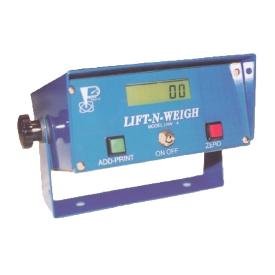
- Page 1 LNW-4 LIFT-N-WEIGH LIFT TRUCK SCALE ON/OFF SWITCH - ZERO BUTTON ACCUMULATE-PRINT OPTION FRONT KEY CALIBRATION OVERLOAD/SETPOINT WARNING OPTION RS232 INTERFACE OPTION Pacific Scale Co. Clackamas, Oregon...
- Page 2 Warranty the scale capacity for lift trucks. THIS SCALE IS A WEIGHT Pacific Scale Co. warrants to the original purchaser that it will repair or replace any part which in its judgement is defective in material or ESTIMATOR AND SHOULD NOT BE USED FOR COMMERCE.
-
Page 3: Table Of Contents
LNW-4 Table Of Contents Important Notice ..................... ii Caution ......................... iii Introduction & Description ..................1 Principle of Operation Pressure Transducer Digital Indication Power Requirements DC Power Filters ....................2 Installation ......................3 Lift Truck Conditions Indicator Installation Hose Installation Installation Diagram .................... -
Page 4: Important Notice
LNW-4 Important Notice Your new LNW-4, Serial No.___________, was calibrated for installation on a ________________ Make _____________ before leaving the factory. Model Please read the Operating Instructions on pages 4 & 5 and Troubleshooting on page 9 before attempting to re-calibrate the indicator. -
Page 5: Caution
Pacific Scale Co., Inc. strongly recommends that when instal- lation procedures are followed which depart from those out- lined herein, the safety of personnel and equipment must be accorded primary consideration. -
Page 6: Principle Of Operation
Note: Many newer systems of 36 Volts or above may need an external Heavy Duty Line Filter (HD-LF) and Heavy Duty Voltage Regulator (HD-VR) to block power spikes from doing damage. Contact Pacific Scale for more information. • 1 •... -
Page 7: Dc Power Filters
LNW-4 DC Power Filters Pacific Scale Co. builds LNW Indicators for use on a wide variety of equipment and vehicles. Our Wide Input Voltage Regulator (WIVR) will work on an input voltage of 12-48 volts DC and has basic power line noise filtering built in. -
Page 8: Installation
LNW-4 Installation - While the LNW indicators are capable of very good accuracy on the RUCK ONDITION test bench, the lift truck condition is the primary limit on accuracy. To achieve the best accuracy possible, usually approximately +/- 1-2% of the capacity of the truck, the lift truck should be in good mechanical and hydraulic condition. -
Page 9: Indicator Installation
LNW-4 Indicator Installation Indicator Installation 1. Power cord should be plugged in and connected preferably direct to the battery. The LNW-4 has it’s own ON/OFF switch and fuse. 2. If the lift truck has twin lift cylinders, be SURE that the hydraulic connection to the LNW-4 is plumbed into the system so it sees the pressure from the two (2) lift cylinders. -
Page 10: Operation
LNW-4 Operation Weighing Reference Point Point established for zeroing and weighing. This point must be within the freelift portion of the uprights . First Stage Cylinder The LIFT-N-Weigh will weigh accurately only in the first stage on a truck with telescoping hoist cylinders. -
Page 11: Operation (Cont.) - Weighing
LNW-4 Operation - Weighing (Continued) Zero Set 1. Bring mast to vertical position. 2. Raise forks 2” or so above weighing mark. 3. Jog forks down to mark and press the ZERO button. ZEROING and WEIGHING must be done in the same manner and at the same point for consistent weights. Weighing 4. - Page 12 LNW-4 Calibration The Lift-N-Weigh is normally precalibrated to the customer supplied lift truck specifications. This is a test bench calibration to the calculated pressure. Because of friction in the lifting mechanism and control valve bleedback, weight errors may exist in the system when installed on the customers equipment.
-
Page 13: Calibration Procedure
LNW-4 Calibration (continued) Step 3 - Set Span. Turn on Display Hold. To enable on Display Hold, first turn unit off. Press and hold the ZERO (Red) button while turning power on. Display will then flash, showing a “P” and some numbers. If there are dashes alternating with the “P xxx”, then Display Hold is off. - Page 14 LNW-4 Calibration (continued) Turn Unit OFF then back ON to return to normal weight mode. Recheck zero, Zeroing if needed. Then pick weight back up to recheck Span. If display shows correct weight, within 2% of capacity, start using scale. If displayed weight is out of tolerance, repeat Step 3 - Set The Span If you do NOT wish to use the Display Hold in regular use, turn off now..
-
Page 15: Troubleshooting
LNW-4 Trouble Shooting Malfunction Probable Cause Corrective Action Indicator does not Power leads reversed. Connect White to Positive, Display numbers Connect Black to Negative Power not connected. Connect per instructions Defective Indicator Replace Indicator or plug Blown WIVR Replace WIVR, add power filter if needed. -
Page 16: Installable Options
For further information contact LNW Tech Support at 1-800-537-1886 ext. 109 Or email: sales@forkliftscales.us Pacific Scale Co. Inc. P.O. Box 1606 Clackamas, OR 97015 US 503-657-7500 1-800-537-1886 Fax: 503-657-5561 © Copyright 2005 Pacific Scale Co., Inc.. All Rights Reserved. -
Page 17: Case Dimensions
LNW-4 LNW 4 Manual Version 6.5 effective 1 Febuary 2007 • 12 •... -
Page 18: Serial Output & Printer Features
LNW-4 LNW 4 Manual Version 6.5 effective 1 Febuary 2007 • 13 •... -
Page 19: Warranty
Such repairs or replacements shall be performed without charge at Pacific Scale’s service facilities. The defective unit is to be returned to Pacific Scale Co., Inc. prepaid with a description of the problem, after calling and receiving a R... -
Page 20: Parts List (Partial)
LNW-4 Parts List, (partial) Description Part NO. ADD/PRINT Button (Green) ..........1 L4-AP-PB Bezel, Silkscreened ............1 L4-BZ Bezel screws ..............4 L4-SZ Display board, Assy............1 L4-DB-ASSY Hose, ...... 1 LC-HH-72 high pressure synthetic, 6’, 1/4” NPT Male each end Hose Fitting, 360 Deg. -
Page 21: Main Board Diagram
LNW-4 TL072CP CKVQ 9903 LNW 4 Manual Version 6.5 effective 1 Febuary 2007 • 16 •...