
Related Manuals for Wurlitzer 7300


Summary of Contents for Wurlitzer 7300
- Page 1 MODEL 7300 ORGAN ,. , T SERVICE INSTRUCTIONS PARTS CATALOG PART No. 131512 ELKHART, IND. THE WURLITZER CO.
- Page 3 COMBO ORGAN...
- Page 4 E D A L E X P R E S S I O N P et e 1 3 05 5 8 C o m p l C a b l e 1 2' lg . - 1 3 0 57 6 ' l g .
- Page 5 M - 7300 COMBO ORGAN Na m e P l a te T o p S c r ew s - 7 6 6 4 9 - 12 ' 13 0 7 1 3 & W a s h e r s - 1...
-
Page 6: Specifications
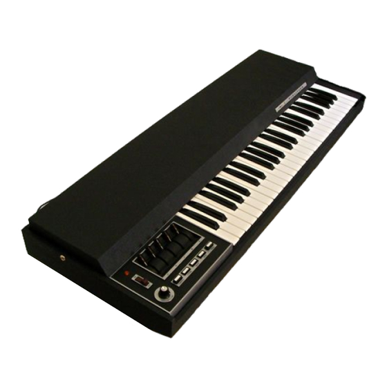
WURLITZER MODEL 7300 COMBO ORGAN The Model 7300 Wurlitzer Combo Organ is a compact organ using the most modern types of semi conductors and integrated circuits (I C) to generate, filter, and amplify the wide range of sounds found in this versitile musical instrument. - Page 7 related and wired directly to the keyboard. This "IC stage then feeds the next IC stage to further divide the signal and again two outputs are available shown as letters H and F and numbered points 22* and 10* wired to the keyboard. The original A signal started out as 7040Hz. and through successive IC circuit dividers finally ended up at ll0 Hz the lowest A found in the combo organ .
- Page 8 K (260) load resistor. The signal is then taken from across this resistor through numbered components 118 and 112 to the base of TR-8. This stage is properly biased to amplify the signal. The output of TR-8 is taken from the collector through numbered component 120 to the Volume Control (264) to ground.
-
Page 9: Maintenance
olated from the 16' - 8' - 4' signal by means of the 4. 7 K (251) resistor. The signal out of the M Control for the IV Mixture will follow the same path as all the rest of the voices through the Pre-Amplifier stage TR-8. -
Page 10: Expression Pedal
Remove the top . Six screws hold the assembly to the case. One sheet metal screw is located just to the left of the "C" oscillator shield can and one to the left of the power transformer and fuse post . This is the longer of the two screws . The remaining screws are ac - cessible by turning the organ over and removing the four screws under which are cup washers . -
Page 11: Electronic Units
TUNING The generators including the master oscillators have been carefully tuned at the factory and should not require any tuning unless some component in the "master oscillator stage" has been changed. The tuning consists of adjusting twelve tuning slugs controlling the top octave notes . Tuning will require the use of a Strobo-Tuner indicator and an insulated tuning hex-head wrench. - Page 12 PARTIAL OPERATION D. Only push botton stops Check wire connections to and operate. from "M" Switch . Check TR -1 Stage . E. Push button stops do not operate. Check TR-1 Check common signal load to all switches. 16' Stop dead. Check TR -7 Stage .
- Page 13 Check . 022 mfd. (130) Capacitor. Check 2 7 K (31) Resistor. Dead Brass Stop. Check Brass Stop Switch. Check TR -3 Stage. Check .01 mfd (51) Capacitor. Check �7 K (60) Resistor. Check Reed Stop Switch. Dead Reed Stop . Check components numbered 62-63- 64-65.
- Page 15 F I LT E R B OA R D M O D E L 7300 CO M B O O RGAN � m · '.. ' �' m � . ' F I LT E R F I LT E R N O T E S I .
- Page 17 GEN E R ATOR P R I NT ED B OA R D CO M BO O RGA N M O D E L 7300 _.,.,,.,- -- ..( © ) 1 3 0 5 3 9 '\ . ----- ---- .- ,...
- Page 19 MODEL 7300 COMBO ORGAN PART NO . PART NO . PART NAME PART NAME Capacit or . 18 MFD. 75 V 76201- 17 1305 83 Top Assembl y 76199- 17 Capacit or . 15 MFD. 75 V Name Pl ate...
- Page 20 PART NO . PART NAME POW ER SUPPLY ASSEMBLY (CONTD . ) 130607 Re ctifie r KEYBLO CK & SWITCH ASSEMBLY CO MPLETE 1305 5 7 130493 Escu tche on - Casting 130591 Switch, Brk t. & Wire Assem bl y 1305 41 Bu tton 130593...
Need help?
Do you have a question about the 7300 and is the answer not in the manual?
Questions and answers