Table of Contents
Advertisement
Advertisement
Table of Contents

Related Manuals for Mizuho osi hana 6875

Summary of Contents for Mizuho osi hana 6875
- Page 1 6875 hana™ HIP AND KNEE ARTHROPLASTY SURGERY TABLE MAINTENANCE & REPAIR hana™ Mizuho OSI 30031 Ahern Avenue Union City, CA 94587-1234 Bus: 510-429-1500 Toll Free: 800-777-4674 Fax: 510-429-8500 http://www.mizuhosi.com/ 0197 Manufactured by Mizuho OSI 2007 U.S. Patents Pending...
-
Page 2: Table Of Contents
TABLE OF CONTENTS 1.0 INTRODUCTION..............................4 1.1 General Description ............................4 1.2 Specifications..............................5 1.3 Shipping................................5 1.4 Storage ................................5 1.5 Glossary of Terms ............................6 2.0 CONTROLS IDENTIFICATION .........................7 2.1 Table Orientation..............................7 2.2 Major Controls Location ..........................7 2.3 Control Panel Identification ..........................8 3.0 BASIC OPERATION ............................9 3.1 Control Operation .............................9 3.2 Caster Floor Locks ............................9 3.3 Moving the Table..............................9... - Page 3 IMPORTANT NOTICES CAUTION: To ensure safe operation of the equipment, please READ THESE INSTRUCTIONS COMPLETELY and keep this manual readily available for future reference. Carefully observe and comply with all warnings, cautions and instructions placed on the equipment or described in this manual. In this manual, the WARNING symbol is intended to alert the user to the presence of important operation, maintenance, or safety instructions.
- Page 4 AVERTISSANT: Si l'intégrité de l'externe protectif terre est en doute, l'équipement sera opéré de son interne électrique pouvoir (pile). This symbol indicates an external ground stud that is required for use when the AC power cable is not connected to a protective earth ground outlet in your operating room or facility.
-
Page 5: Introduction
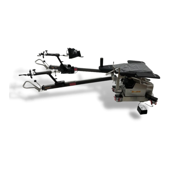
1.0 INTRODUCTION 1.1 General Description The OSI 6875 hana™ Surgery Table is designed to hold a patient undergoing the single incision, tissue sparing Anterior Approach Total Hip Replacement and Total Knee Arthroplasty surgical procedures. It is a stand-alone, single-pedestal, AC powered or internal battery operated table designed to position a patient in a supine position during surgical procedures. -
Page 6: Specifications
1.2 Specifications The 6875 hana™ Table is Class 1 Exempt, Type B Medical Device with an IPX-O rating. The table is designed to position a patient weighing up to 450 pounds (205 kg). Table length (with Leg Spars installed and parallel) is 125 inches (3175 mm). Table width (at base) is 35 inches (889 cm). -
Page 7: Glossary Of Terms
1.5 Glossary of Terms The glossary of terms assumes the patient is supine with their head at the “Head-end of the Table” (toward Control Panel) and their feet are at the “Foot-end of the Table” (toward Leg Spars). The Hand Pendant functions are oriented for this position only. -
Page 8: Controls Identification
2.0 CONTROLS IDENTIFICATION 2.1 Table Orientation The major components of the 6875 hana™ Table are identified below. The table is described as having a "Head End" and a "Foot End". The On/Off Power Switch and the Power Cord receptacle are located at the "Head End"... -
Page 9: Control Panel Identification
2.3 Control Panel Identification Femur Lift Power Control Indicator Control Pad Section Section Control Panel The Control Panel is divided into 3 sections: Section 1: Femur Lift control section. Selection switch to change between Right and Left Femur Lift operation. Indicators to show if Femur Lift is connected (Left, Right). Indicator to show if Foot Pedal is connected. -
Page 10: Basic Operation
3.0 BASIC OPERATION 3.1 Control Operation Plug the power cord into the power cord receptacle, located at the Head End of the table and into a properly grounded receptacle. Refer to the Model/Serial Number label on the Head End of the table for input voltage requirements. -
Page 11: Hand Pendant Control
3.4 Hand Pendant Control The 6875 hana™ table is controlled by means of a Hand Pendant. The Hand Pendant is plugged into the receptacle labeled “HAND PENDANT” on the Control Panel. Flip main “ON/OFF Power Switch to “OFF”. Plug in Hand Pendant connector and rotate screw-locking collar clockwise until hand tight. Flip main “ON/OFF Power Switch to “ON”, wait twenty seconds for table to “boot-up”... -
Page 12: Leg Spars
3.5 Leg Spars The 6875 hana™ table is equipped with two adjustable Leg Spars. Each Leg Spar is designed to support the foot in the traction boot and allow for abduction, adduction, raising or lowering of the leg. When the leg is in a desired position the spar can be locked to maintain that position. A dial is provided to gauge the degree of internal and external rotation and should be zeroed out and locked in place utilizing the thumb screw when the foot is in the neutral position. -
Page 13: The Electrical System
4.0 THE ELECTRICAL SYSTEM 4.1 Description The electrical system provides control of all table functions and is comprised of a power cord, an On/Off circuit-breaker switch, wire harnesses, a power supply, a controller circuit, a hand pendant, floor lock jackscrew-actuators, and various electromechanical actuators. Electric motor-driven lead-screw actuators manipulate the table height, lateral roll and Trendelenburg functions. -
Page 14: Battery System
4.5 Battery System The 6875 hana™ Table is equipped with a battery system, which consists of two 12 volt batteries in series to provide 24 volts. Due to the relatively low power consumption of the 6875 hana™ Table, it can be used on battery power for up to 12 hours at 10% duty cycle. -
Page 15: Inspection
5.0 INSPECTION 5.1 Acceptance & Transfer Please refer to the 6875 hana™ Table User Guide (part number NW0466). 5.2 Per-procedure/Post-procedure Please refer to the 6875 hana™ Table User Guide (part number NW0466). 5.3 Semi-Annual It is recommended to perform a Preventative Maintenance (PM) check of your 6875 hana™ Table (see Section 7 Maintenance). -
Page 16: Function Check
6.0 FUNCTION CHECK Perform all steps in this procedure. For a complete definition of terms used in this procedure, please refer to the “Glossary of Terms” section of the manual. 1. Plug in the Hand Pendant. Verify the main “ON/OFF” Power Switch is “OFF” (located on table base front, below Control Panel). Plug the Hand Pendant cable-connector into the "HAND PENDENT"... - Page 17 • Move Table Top out of level by raising height approximately two inches, tilting tabletop (left or right) and activate Trendelenburg approximately five degrees. Press and hold the "RETURN TO LEVEL" button and observe that the tabletop: 1) Levels the Lateral Roll. 2) Levels the Trendelenburg.
- Page 18 • Move tabletop out of level by raising height approximately two inches, tilting tabletop (left or right) and activate Trendelenburg approximately five degrees. Press and hold the "RETURN TO LEVEL" button and observe that the tabletop: 1) Levels the Lateral Roll. 2) Levels the Trendelenburg.
-
Page 19: Maintenance
7.0 MAINTENANCE 7.1 Cleaning and Disinfection NOTE: Never pour any liquid directly onto the table. Never subject the 6850 Table to an equipment washing machine. USE OF IODOPHORS WILL CAUSE STAINING. Table Exterior: 1. Exterior surface should be regularly wiped clean with a mild detergent solution and wiped dry with a soft lint-free cloth. -
Page 20: Adjustment - Spar Ball-Joint Lock Handle
7.2 Adjustment - Spar Ball-joint Lock Handle Overview: With break-in wear the patient leg “Spar Ball Joint Lock” handle (Lock Handle) may require adjustment to allow proper functionality. If the Spar does not move freely when the Lock Handle is in “Unlock” position, or does not hold position when handle is in “Locked”... -
Page 21: Troubleshooting
8.0 TROUBLESHOOTING 8.1 Table Malfunction • Check input power; verify Power Cord is plugged into a live electrical outlet. • Verify Power Switch is “ON”; the switch illuminates green. 8.2 Diagnostics Tree Table is “dead”; no functions are operational. • Verify Power Cord is plugged into an appropriate AC receptacle and into the Power Cord Socket (located on table-base panel). -
Page 22: On-Line Diagnostics
• Call OSI Technical Service (800-777-4674) for parts or repair. “Left Lateral Roll” or Right Lateral Roll” not functioning. • Verify Power Cord is plugged into an appropriate AC receptacle and into the Power Cord Socket (located on table-base panel). •... -
Page 23: Removal And Replacement Of Components
9.0 REMOVAL and REPLACEMENT of COMPONENTS 9.1 Hand Pendant Control Part Number: 6807-4 Hand Pendant Control 1. Disconnect Hand Pendant bayonet-type connector from front panel. 9.2 Foot Control Part Number 6875-5003 Foot Control 1. Disconnect Foot Control eight-pin DIN connector from rear panel. 6875 hana™... -
Page 24: Motion-Control Module
9.3 Motion-Control Module Part Number: 100VAC 6875-4004, 110VAC 6875-4001, 220VAC 6875-4000 Motion-Control Module 1. Disconnect Hand Pendant bayonet-type connector from front panel. 2. Remove Motion-Control Module cover by removing four #10 screws. 3. Remove two ¼-inch screws. 4. Slide-out Motion-Control Module away from base about six inches. 5. -
Page 25: Internal Batteries
9.4 Internal Batteries Part Number: NV0801 Battery Location (Base Cover Removed) If battery fails to hold a charge it should be replaced (see Section 4.5 Battery System). • Replace only with identical type and size battery. • Replace both batteries at the same time (also, if needed, foam battery blocks on top of battery). •... -
Page 26: Leg Spar Rotation Wheel
Battery replacement: 1. Disconnect both each cable from the positive (+ / red) battery terminals. 2. Disconnect both each cable from the negative (- black) battery terminals. 3. Remove two ¼-20 nuts from battery securing bolts (on each side of each battery). 4. - Page 27 9.6 Table Lift Assembly Part Number NL1254 Table Lift Assembly 1. Cover removal. a. Remove top-bellows bolts. b. Remove bottom-bellows bolts. c. Remove ten #6 screws from top sheet metal cover. d. Remove five 10-32 screws from top sheet metal cover. e.
-
Page 28: Tilt / Trendelenburg Assembly
9.7 Tilt / Trendelenburg Assembly Part Number NL1255 Table Tilt / Trendelenburg Assembly 1. Cover removal. a. Remove top-bellows bolts. b. Remove bottom-bellows bolts. c. Remove ten #6 screws from top sheet metal cover. d. Remove five 10-32 screws from top sheet metal cover. e. -
Page 29: Femur Lift Assembly, Left / Right
9.8 Femur Lift Assembly, Left / Right Part Number: Right 6875-600 / Left 6875-601 1. Disconnect twist-lock 24 VDC electrical connector from damaged Femur Lift Cylinder. 2. Remove Femur Lift Locking knob. 9.9 Caster(s) Part Number: ND0443 1. Loosen the four 3/8 x 1-inch Caster mounting bolts at the damaged Caster. 2. -
Page 30: Technical Drawings And Parts Lists
10.0 TECHNICAL DRAWINGS and PARTS LISTS 10.1 Standard Components Identification Chart Table Assembly, Right Side (covers removed) 10.2 Replacement / Spare Parts List • Hand Pendant Control p/n 6807-4 • Foot Control p/n 6875-5003 • Motion-Control Module, 100VAC p/n 6875-4004 •... -
Page 31: Osi Technical Service
11.0 OSI TECHNICAL SERVICE Contact for Parts and Service: For detailed repair information or to order replacement parts, call the OSI Technical Services Department: A Technical Services representative is available from 7AM-5PM PST, Monday through Friday. Please leave a message before or after business hours. Please state;...
Need help?
Do you have a question about the hana 6875 and is the answer not in the manual?
Questions and answers