
Subscribe to Our Youtube Channel
Summary of Contents for InterTest iShot Imaging MZ4 HD-UV GTIS
- Page 1 MZ4® HD-UV Gun Tube Inspection System Operation and Service Manual Version 1.1 • June 2013 Publication Number INT-080 rev1...
- Page 2 IMPORTANT: If you are in possession of a printed or electronic version of this document, be aware that it may not be the current version. To ensure that you are using the most up- to-date version of this document, please contact the InterTest Customer Service and Support Group.
-
Page 3: Table Of Contents
InterTest, Inc. • 908-496-8008 MZ4® HD-UV Gun Tube Inspection System Table of Contents Chapter 1 — Preface and General Information ..................5 ..About This Manual ........................... 5 Disclaimer ..........................5 Purpose ............................. 5 ..OSHA Compliance and Safety Guidelines..................5 ... - Page 4 InterTest, Inc. • 908-496-8008 MZ4® HD-UV Gun Tube Inspection System Chapter 5 — Components and Part Catalog ..................29 Chapter 6 — Service and Maintenance Records ................... 36 List of Figures Figure 1 — Manual Version Information ....................... 6 Figure 2 — MZ4 HD-UV Gun Tube Inspection System (not assembled) ........... 10 Figure 3 —...
-
Page 5: Chapter 1 - Preface And General Information
It is the responsibility of the technician or other service personnel to adhere to all OSHA guidelines as they concern PPE devices and their proper use. Revision Information As it becomes necessary to revise this manual, InterTest will give the reasons for the revision in this. Version 1.1 • June 2013 Page 5... -
Page 6: Manual Versions
When troubleshooting a problem that may occur, InterTest Customer Service and Support Personnel may ask for this information in order to ensure that the user is referencing a suitable version of the manual. -
Page 7: Safety Considerations
Never remove the top cover of the controller. Electrical shock hazards exist due to high internal voltage. There are no user-serviceable parts inside the controller, except for fuses, which are accessible via the rear panel. Refer all service to the InterTest Customer Service and Support Group. - Page 8 To avoid injury, read and understand the associated documentation for MZ4 HD-UV Gun Tube Inspection System component prior to attempting operation. Direct any questions about equipment operation to the InterTest Customer Service and Support Group at 908- 496-8008 or via email to service@intertest.com.
- Page 9 InterTest, Inc. • 908-496-8008 MZ4® HD-UV Gun Tube Inspection System it is not intended or for environments for which it is not intended will void the warranty. Warranty information can be found starting on Page 15. CAUTION: The UVA output is an eye and skin hazard. Do not allow close or prolonged exposure to the UVA output of the MZ4 HD-UV Gun Tube Inspection System.
-
Page 10: Chapter 2 - Introduction To The Mz4 Hd-Uv Gtis
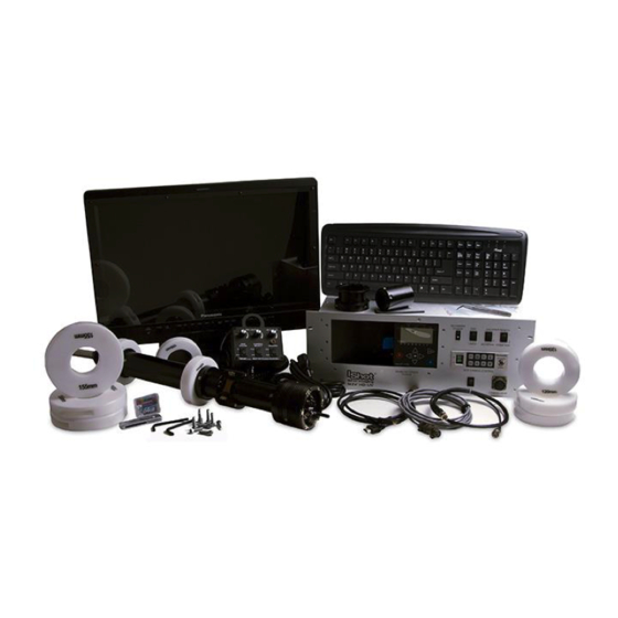
Chapter 2 — Introduction to the ® HD-UV GTIS Overview Figure 2 shows the MZ4 HD-UV Gun Tube Inspection System Figure 2 — MZ4 HD-UV Gun Tube Inspection System (Also includes 4 x 6’ Insertion Poles, 25’ BNC Cable, 25’ HDMI Cable, Monitor Swing Arm Mount not shown) Version 1.1 •... -
Page 11: Mz4 Hd-Uv Gtis Components Description
InterTest, Inc. • 908-496-8008 MZ4® HD-UV Gun Tube Inspection System MZ4 HD-UV GTIS Components Description The MZ4 HD-UV Gun Tube Inspection System Components are detailed below in Figure 3 and Table C. NOTE: For ordering information refer to the Parts Catalog chapter beginning on Page 29. -
Page 12: Table C - Mz4 Hd Uv Gun Tube Inspection System Components Description
InterTest, Inc. • 908-496-8008 MZ4® HD-UV Gun Tube Inspection System Figure 3 — MZ4 HD-UV Gun Tube Inspection System Components Description (Not Assembled) Table C — MZ4 HD-UV Gun Tube Inspection System Components Description Item Description 21” Panasonic HD Monitor... -
Page 13: System Features
InterTest, Inc. • 908-496-8008 MZ4® HD-UV Gun Tube Inspection System 4 x 6’ Insertion Pole sections Shown 25’ BNC Video Cable Shown 25’ HDMI Video Cable Shown Monitor Swing Arm Mount Shown System Features The system is designed for the internal visual inspection of gun tubes, mortars, howitzers, and cannons utilizing white and/or UV illumination. -
Page 14: Specifications
InterTest, Inc. • 908-496-8008 MZ4® HD-UV Gun Tube Inspection System Specifications Refer to Table D for general specifications and Table E for forward and side camera specifications. Table D — General Specifications Item Description Camera Rack Mount Controller Console Records, Adjusts Focus & Light Intensity... -
Page 15: Customer Support
InterTest, Inc. equipment. This warranty shall not apply to any equipment that has been subject to accident, negligence, alteration, abuse, unauthorized repair, improper storage, or other misuse. -
Page 16: Returns For Repair Or Service
Return Procedure Once a product is received by InterTest, Inc. it will be evaluated by one of our qualified technicians. The fee for any repair evaluation not sent in under warranty is $55 (USD). This cost is in addition to any other charges required. - Page 17 To unpack the system, first remove all tape and packing material from the components. Next, carefully inspect each piece for damage and/or missing parts. Inspect all control panel knobs and switches for proper operation. If any portion of the system has suffered damage during shipment, notify InterTest Customer Support Group at once.
-
Page 18: Chapter 3 - General Operation And Components
Chapter 3 — General Operation and Components Introduction This chapter describes how to assemble and prepare the system for use. Sections include the following: Assembly Guidelines System Assembly Procedure Rack Mount Camera Control Box Functions Pendant Controller Functions ... -
Page 19: Figure 4 - Insert Power Video Cable Into Insertion Pole Base
InterTest, Inc. • 908-496-8008 MZ4® HD-UV Gun Tube Inspection System To assemble the system, perform the following steps: (1) Refer to Figure 4: Take 6’ insertion pole with the section that starts at 13 inches and slide over and up the 15 meter Power Video Cable off the back of the Camera Head. Once the pole meets the base of the Camera Head, thread together. -
Page 20: Figure 6 - Thread In Bumper Guard Into Camera Head
InterTest, Inc. • 908-496-8008 MZ4® HD-UV Gun Tube Inspection System (3) Refer to Figure 6: thread the Bumper Guard into the Camera Head. Figure 6 — Thread in Bumper Guard into Camera Head (4) Refer to Figure 7: Mount the Centering Rings to the Camera Head. First, remove the 2 threaded cap screws on either side of each of the centering rings (105, 120, or 155mm) with provided hex head wrench. -
Page 21: Figure 8 - Camera Head With Centering Rings Attached
InterTest, Inc. • 908-496-8008 MZ4® HD-UV Gun Tube Inspection System Figure 8 — Camera Head Shown with Centering Rings Attached (5) Refer to Figure 9: Prior to this step, be sure the Main Power switch is in the OFF position on the front panel of the Rack Mount Control Box. -
Page 22: Figure 10 - Back Of 21" Panasonic Monitor
InterTest, Inc. • 908-496-8008 MZ4® HD-UV Gun Tube Inspection System 25’ HDMI Cable from Control Box 25’ BNC 6’ AC Power Cable from Cord to Wall Control Box Socket Figure 10 – Back Panel of 21” Panasonic Monitor (7) Refer to Figure 11: Turn ON “Main Power” and “DC Power” on Panasonic Camera Control unit. -
Page 23: Rack Mount Control Box Functions
InterTest, Inc. • 908-496-8008 MZ4® HD-UV Gun Tube Inspection System Rack Mount Control Box Functions Refer to Figure 1212/Table F and Figure 13/Table G - (Rack Mount Control Box features and functionality, front and back): The console is equipped with a built-in nanoFlash DVR, encoder control, an HD Camera Control Unit for the Side View Camera, and a connection on the back for the Pendant Controller. -
Page 24: Figure 13 - Back Of Rack Mount Control Box Functions
InterTest, Inc. • 908-496-8008 MZ4® HD-UV Gun Tube Inspection System Figure 13 – Back of Rack Mount Control Box Functions Table G – Back Rack Mount Control Box Functions Feature Description PS2 Keyboard Input Insertion Encoder Slot Cooling Fans 110/220 VAC, 50-60Hz Power Input Pendant Controller Input HD-SDI OUT –... -
Page 25: Figure 14 - Pendant Controller Functions
InterTest, Inc. • 908-496-8008 MZ4® HD-UV Gun Tube Inspection System Refer to Figure 13/Table H: (Pendant Controller features and functionality). Figure 14 — Pendant Controller Functions Table H – Pendant Controller Functions Feature Description Fore Lamp Adjust – When (F) is selected, “Fore” controls intensity of the front 6 white light lamps. -
Page 26: Control Box Console Dvr
InterTest, Inc. • 908-496-8008 MZ4® HD-UV Gun Tube Inspection System Table I – PS2 Keyboard Commands Keyboard Command Description Edit User Field #1..4 Exit Edit dialog. Save Changes Exit Edit dialog. Do NOT Save Changes. If no dialog is active, Clear screen and execute Macro#00... -
Page 27: Chapter 4 - Care And Maintenance
NOTE: This procedure ONLY applies to both forward and side-facing WHITE LIGHT lamps. DO NOT attempt to change the UV LEDs if they go out. Instead, return the system to InterTest Inc. for a repair evaluation. An RMA (Return Merchandise Authorization Number) must be issued prior to the unit being returned. -
Page 28: Changing The Fuse
Changing the Fuse IMPORTANT: If after replacing the fuse it again blows, STOP. The MZ4 HD-UV Gun Tube Inspection System needs immediate attention. Contact the InterTest Customer Support Group at 908-496-8008 or via email to service@intertest.com. IMPORTANT: Before proceeding with the steps that follow power down the controller and disconnect the unit from the main power source. - Page 29 Chapter 5 — Components and Part Catalog The following is a list of components and parts that may be purchased as replacements or as optional accessories. EM Number Description Reference Image EM18170 MZ4 HD-UV Gun Tube Inspection System Panasonic HD-SDI/HDMI 21” EM17830 Monitor Version 1.1 •...
- Page 30 InterTest, Inc. • 908-496-8008 MZ4® HD-UV Gun Tube Inspection System EM Number Description Reference Image EM16935 nanoFlash DVR EM18121 Rack Mount Controller EM18168 Pendant Controller Version 1.1 • June 2013 Page 30...
- Page 31 InterTest, Inc. • 908-496-8008 MZ4® HD-UV Gun Tube Inspection System EM Number Description Reference Image EM18097 MZ4 HD-UV Camera Head Assembly EM153285 Flextube Anchor Assembly EM18101 Insertion Pole Sections Version 1.1 • June 2013 Page 31...
- Page 32 InterTest, Inc. • 908-496-8008 MZ4® HD-UV Gun Tube Inspection System EM Number Description Reference Image EM18098 105mm Centering Ring EM18199 120mm Centering Ring EM18100 155mm Centering Ring 25’ HDMI to HDMI Cable EM67887 Version 1.1 • June 2013 Page 32...
- Page 33 InterTest, Inc. • 908-496-8008 MZ4® HD-UV Gun Tube Inspection System EM Number Description Reference Image 25’ BNC to BNC Video Cable EM41321 6’ AC Power Cord EM11890 EM66498 USB CF Card Reader Version 1.1 • June 2013 Page 33...
- Page 34 InterTest, Inc. • 908-496-8008 MZ4® HD-UV Gun Tube Inspection System EM Number Description Reference Image EM18136 64 GB Compact Flash (CF) Card EM63732 XENON Lamp Replacement EM63087 Set of Two Spare Fuses (EM63087, 2 A Slo-Blo, 250 V) Version 1.1 • June 2013...
- Page 35 InterTest, Inc. • 908-496-8008 MZ4® HD-UV Gun Tube Inspection System EM Number Description Reference Image EM61646 Lamp Extraction Tool EM15259 Computer Keyboard Version 1.1 • June 2013 Page 35...
-
Page 36: Chapter 6 - Service And Maintenance Records
Chapter 6 — Service and Maintenance Records Product: MZ4 HD-UV Gun Tube Inspection System Date of Purchase: Date Service Performed Version 2.0 • October 2009 MPH-900-OCUM Page 36... - Page 37 InterTest, Inc. • 908-496-8008 MZ4® HD-UV Gun Tube Inspection System NOTES: Version 1.1 • June 2013 Page 37...
- Page 38 InterTest, Inc. • 908-496-8008 MZ4® HD-UV Gun Tube Inspection System NOTES: Version 1.1 • June 2013 Page 38...
- Page 39 InterTest, Inc. • 908-496-8008 MZ4® HD-UV Gun Tube Inspection System Version 1.1 • June 2013 Page 39...
Need help?
Do you have a question about the iShot Imaging MZ4 HD-UV GTIS and is the answer not in the manual?
Questions and answers