
Subscribe to Our Youtube Channel
Related Manuals for Evil Mad Scientist AxiDraw MiniKit 2

Summary of Contents for Evil Mad Scientist AxiDraw MiniKit 2
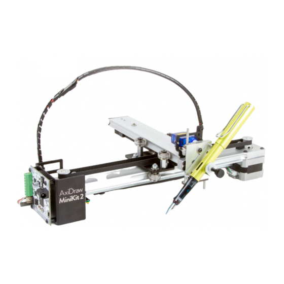
- Page 1 AxiDraw MiniKit 2 Assembly Guide Model 2542 AxiDraw MiniKit 2 Assembly guide v 2.5 https://emsl.us/924 Last updated: May 8, 2021...
-
Page 2: Table Of Contents
Table of Contents Table of Contents ..........2 3.3 Spacers, shims, and washers ....23 Introduction ............4 3.4 X Carriage Idler Pulleys ......24 About this guide and this kit ......4 3.5 Y Wheel Supports ........25 Getting help ........... 4 3.6 Preset Y Eccentrics ........ - Page 3 5.1 Parts used in Servo and Wiring ....56 5.2 Stepper wiring 1 ........57 5.3 Stepper wiring 2 ........58 5.4 Cable guide wrapping ......59 5.5 Mounting the servo ........ 61 5.6 Mount the cable guide ......62 5.7 Complete the wiring ......
-
Page 4: Introduction
Software About this guide and this kit Towards the end of this guide, you will need AxiDraw soft- This is the assembly guide for AxiDraw MiniKit 2, a com- ware on your computer. Get started at: axidraw.com/sw pact “DIY kit” version of the AxiDraw writing and drawing machine. -
Page 5: Part 1: Tools
Part 1: Tools... -
Page 6: Required Tools
1.1 Required tools To assemble the AxiDraw MiniKit, you will need certain general-purpose tools that are not included with the kit. These required tools are: 1. Either A scissors or B wire clippers 2. A Phillips #1 size screwdriver, C 3. -
Page 7: Included Tools
1.2 Included tools Several specific tools are included with the kit. We will refer to these, and other parts included with the kit, by part numbers. The included tools are: #1, 15 cm / 6 inch Ruler #2, T20-size Torx L-wrench #3, 2 mm Ball-end Hex L-wrench #4, 2.5 mm Hex L-wrench #5, 10 mm Low-profile Wrench... -
Page 8: Part 2: The Base
Part 2: The Base... -
Page 9: Parts In The Base Assembly
2.1 Parts in the base assembly #8, MiniKit Base Rail (1) #15, M3×14 Button-head Screw (8) #22, Black Nylon Spacer (4) #9, Ballast Weight (1) #16, X Endstop (2) #23, M3 Kep Nut (4) #10, Nylon Loop Clamp (2) #17, M4×12 Torx Tapping Screw (4*) #24, M4×8 Torx Tapping Screw (4*) #11, M4×20 Torx Tapping Screw (2) #18, EBB Driver Board (1) -
Page 10: Ballast Weight
2.2 Ballast Weight The ballast weight may have sharp edges; Handle with appropriate care. 1. Identify the Base Rail #8, the Ballast Weight #9, the two nylon loop clamps #10, and the M4×20 Torx tapping screws. These screws can be identified by the star-shaped socket on their heads and length of approximately 20 mm, as measured below the head (A). - Page 11 §2.2 Ballast Weight, continued 5. Place the Ballast Weight on top of the Base Rail, lining up the two pairs of holes, and insert the tips of the screws through the two pairs of holes. Orient both loop clamps so that they point “straight out”...
-
Page 12: Add Pulleys To Motors
2.3 Add pulleys to motors 1. Locate the flat face (A) on the shafts of the stepper motors, #13. 2. Observe that the timing belt pulleys, part #14, each have two set screws (B). The wrench for these screws is the 2 mm Ball-end Hex L-wrench #3. - Page 13 §2.3 Add pulleys to motors, continued 5. Firmly tighten the set screw against the flat face of the motor shaft, using the short end of the hex wrench (E). 6. Tighten the second set screw on the pulley, again using the short end of the hex wrench.
-
Page 14: Install The Motors
2.4 Install the motors 1. Attach the connector on the Long Motor Wire Harness to one of the two stepper motors (A). 2. Rotate the motor and feed its pulley through the large hole in the Base Rail (B), taking care to not pull the cable out of the loop clamps. - Page 15 §2.4 Install the motors, continued 4. Set the Base Rail down on top of the two motors, and check their orientation: The connectors on both motors should face towards the center of the base rail (D). 5. Identify the M3×14 Button-head Screws, #15. These can be identified by their black color and length of approximately 14 mm, as measured below the head.
-
Page 16: Endstops
2.5 X Endstops 1. Identify the X Endstops #16 and the M4×12 Torx Tapping Screws, #17. The X Endstops are black plastic blocks with a hole through the center. There may be a tab (A) on one side of the Endstop. The screws have silver color, a star-shaped socket on the head, and a length of approxi- mately 12 mm, as measured below the head. -
Page 17: Mounting The Ebb
2.6 Mounting the EBB 1. Identify the EBB Driver Board #18, and the EBB Support #19. You will also need the four long, black M3×16 Button-head Screws #20, the White Nylon Washers #21, the Black Nylon Spacers #22, and the M3 Kep Nuts #23. - Page 18 §2.6 Mounting the EBB, continued 4. Orient the EBB Support such that the power jack and USB port face towards the “Axidraw MiniKit 2” logo. Then, two at a time, guide the four screws into the corner holes of the EBB support (D).
- Page 19 §2.6 Mounting the EBB, continued 7. Attach the EBB Support to the Base Rail, using two of the #24 M4×8 Torx Tapping Screws. These screws have silver color, a star-shaped socket on the head, and a length of approximately 8 mm, as measured below the head. The screws go through the flange in the EBB support and into the two remain- ing holes on the top of the Base Rail.
-
Page 20: Part 3: The X Carriage
Part 3: The X Carriage... -
Page 21: Parts In The X Carriage Assembly
3.1 Parts in the X Carriage Assembly #25, Carriage Plate (1) #31, Stamped Washer, M4×10×1 (4) #37, M4×22 Button-head Screw (5*) #26, Y Endstop (1) #32, MF104 Ball Bearing (8) #38, Roller Wheel (8*) #27, M4×12 Low Profile Screws (10*) #33, M4×8×12 Hex Standoff (2) #39, M4 Nylon locknut (4) #28, Precision Shim, M4×8×0.5 (4) -
Page 22: Install The Y Endstop
3.2 Install the Y Endstop 1. Orient the Carriage Plate #25 top-side up: With the large notch – the front of the plate – facing you, the two larger holes should be on the right-hand side of the part as shown (A). -
Page 23: Spacers, Shims, And Washers
3.3 Spacers, shims, and washers There are several types of round spacers in the X Carriage. Since they are similar in appearance, let’s take a closer look. All four of these parts are made of stainless steel, with a 4 mm clearance hole in the center. -
Page 24: Carriage Idler Pulleys
3.4 X Carriage Idler Pulleys 1. Identify part #32, the MF104 Ball Bearings. There are 8 of these, and they are smaller size of the ball bearings with flang- 2. Assemble these bearings into four stacks of two, lined up with the flanges facing away from each other –... -
Page 25: Y Wheel Supports
3.5 Y Wheel Supports 1. Identify parts #33, and #34, threaded hexagonal standoffs, each 12 mm long. The straight hexagonal prisms are #33, the M4×8×12 Hex Standoffs. Parts #34 are the “SemiHex” Standoffs, with a 10 mm hex section on the lower half only. 2. - Page 26 §3.5 Y-Wheel supports, continued 5. Using the 2.5 mm Hex L-wrench #4 and the 8 mm Low-profile Wrench #6, firmly tighten the two hex standoffs into place (C). Tip: In cases like this – more are coming – it is usually easiest hold the hex standoff (or hex nut) steady with the open-ended wrench, while you turn the screw with the hex L-wrench.
- Page 27 §3.5 Y-Wheel supports, continued 8. Slip another M4×10 Button-head Screw through the hole in each Eccentric Spacer (F). 9. Thread a SemiHex Standoff #34 onto each of the pro- truding screws, with the wide hexagonal surface down, in contact with the Carriage Plate. 10.
-
Page 28: Preset Y Eccentrics
3.6 Preset Y Eccentrics The Eccentric Spacers can be rotated to move the screw position closer to or further from the centerline of the Car- riage Plate. The two that have been added thus far will be used to adjust the Y Carriage in a later step. Rotate the two Eccentric Spacers, using the 8 mm Low-pro- file Wrench #6, such that the screw heads are as far as possi- ble from the centerline of the carriage plate. -
Page 29: Front X Wheels
3.7 Front X Wheels 1. Identify parts #37, #38, and #39, the M4×22 But- ton-head Screw, Roller Wheels, and M4 Nylon Locknuts. The screws are the longest in the kit, 22 mm long, with a hexagonal socket on the head. The M4 Locknuts have a hexagonal outline and rounded tops. - Page 30 §3.7 Front X Wheels, continued 5. Tighten both wheels securely in place using the 2.5 mm Hex L-wrench #4 and, the 7 mm Low-profile Wrench #7 to steady the locknut (C). Important: Do not overtighten the wheels. The wheels should be secure in place but the outer clear plastic part of the wheel must be able to turn freely.
-
Page 31: Rear X Wheels
That is, the front side – with the notch and two wheels – should face towards you #35, Eccentric Spacer when the EBB support (with its AxiDraw MiniKit 2 logo) is on the left and facing towards you (A). #29, Shim, M4×8×1 2. - Page 32 §3.8 Rear X Wheels, continued 5. Now, tighten both wheels – only until barely tight – us- ing the 2.5 mm Hex L-wrench and the 7 mm Low-profile Wrench #7 to steady the locknut. It is easiest to tilt the assembly forward while doing so (D).
-
Page 33: Tuning The X Carriage
3.9 Tuning the X Carriage In this step we will adjust the position of the two rear wheels using the Eccentric Spacers located above them. The goal will be to tune the tension between the Roller Wheels and the Base Rail, so that the carriage moves smoothly and without slack. - Page 34 §3.9 Tuning the X Carriage, continued 4. If you can feel any slack movement in Pair 1 alone, make a small adjustment to the eccentric position (C), and test again. Repeat until there is no slack movement in line with these two wheels.
-
Page 35: Part 4: Y, Belt, And Z
Part 4: Y, Belt, and Z... -
Page 36: Parts In The Y, Belt, And Z Assemblies
4.1 Parts in the Y, Belt, and Z assemblies #40, MiniKit Y Rail (1) #45, M4×16 Button-head Screw (2) #50, M3×8 Button-head Screw (1) #41, M4 Square Nut (3) #46, Y EndCap (1) #51, Servo Mount (1) #42, Tensioning Block (1) #47, Timing Belt (1) #52, Z Slide Assembly (1) #43, F624 Ball Bearing (2) -
Page 37: Tensioning Block
4.2 Tensioning block Aluminum extrusions like the Y Rail may have extremely This side up. sharp points and edges. Handle with appropriate care. 1. Begin with the MiniKit Y Rail #40. For this step, orient it as Note shape shown (A), with the further-apart set of openings visible on of openings the end facing up. -
Page 38: Y Carriage Idler Pulley
4.3 Y Carriage Idler Pulley In this step you will install the “Idler Pulley”, at the front of the #29, Shim M4×8×1 Y Carriage. 1. Identify part #43, the 2 large flanged ball bearings, type #43, Flanged bearings F624. 2. Slip the remaining #37 M4×22 Button-head Screw through #37, M4×22 Screw the two ball bearings, with the flanges facing away from each other –... -
Page 39: Y Carriage Travel Limits
4.4 Y Carriage Travel Limits 1. Identify part #44, the M4×8×8 Hex Standoffs. These are threaded hexagonal pieces 8 mm across and 8 mm tall. 2. Also identify M4×16 Button-head Screws #45, silver in col- or, with a hexagonal socket on the head, and a length of approximately 16 mm under the head. -
Page 40: Y Endcap And Pre-Threading
4.5 Y Endcap and Pre-threading 1. Identify the Y Endcap #46 and locate the two remaining the M4×8 Torx Tapping Screws #24. 2. Position the endcap on the “back” end of the Y Rail, which is the end with the Tensioning Block. Align its two holes with the matching holes in the end of the Y Rail, and its outline to the shape of the Y Rail. -
Page 41: Fixed Y Wheels
4.6 Fixed Y Wheels Next, attach Roller Wheels #38 to the top of the two tall and straight M4×8×12 Hex Stand- offs #33 on the left side of the X Carriage. These are the fixed (not adjustable) wheels for the Y axis. Use two of the M4×12 Low Profile Screws #27, and tighten them securely in place with the short side of the correct Hex L-wrench. -
Page 42: Aside: Axidraw Kinematics
4.7 Aside: AxiDraw kinematics In the next step we will begin adding the timing belt to the kit. It is helpful to understand how the belt is arranged – and thus how the machine works – before doing so. The AxiDraw is driven by two stepper motors, each rigidly fixed to the base of the machine. Each motor drives a timing belt pulley that is attached directly to the motor shaft. -
Page 43: Belt Staging
4.8 Belt Staging 1. Set the Timing Belt #47 roughly in place. Posi- tion its loose ends out the back of the carriage and with a loose loop out the front side of the carriage (A). 2. Loop the belt over both timing belt pulleys, and make sure that the teeth on the belt are “point- ing in”... - Page 44 §4.8 Belt Staging, continued 4. Once the belt seems to be in the right place, test its placement by pulling the loose ends (pinched together) straight back while pulling the front loop straight forward (D). 5. While holding the belt in tension, make sure that it is flat and not twisted, engaged in the teeth of both motors, engaged between the flanges the four idler pulleys, and not looped around anything that it isn’t supposed to be.
-
Page 45: Add The Y Carriage
4.9 Add the Y Carriage 1. Set the Y Carriage in place atop the X Carriage, with its idler pulley pointing down and towards the front of the X carriage – towards the side with the belt loop, not the loose belt ends. 2. -
Page 46: Belt Tensioning
4.10 Belt tensioning 1. Loop the belt over the Y Carriage idler pulley. 2. Holding both X and Y carriages to prevent them from sliding, turn the full assembly upside down (A). Tip: It may be helpful to rest the assembly on your lap or on a large cup or bowl while inverted. - Page 47 §4.10 Belt tensioning, continued 4. Loop one end of the belt around the rounded post near the end of the Tensioning Block, and fold it back up so that the belt teeth engage with each other. 5. Holding the belt steady by the engaged teeth (B), pull the loose end to establish a little tension and en- sure that the belt is still looped around the motors and pulleys.
- Page 48 §4.10 Belt tensioning, continued 7. Insert the Belt Spacer, with its recessed side facing up, into the gap in the middle of the Tensioning Block (D). Its func- tion is to pinch the two looped ends of the belt, and thus anchor the belt.
- Page 49 §4.10 Belt tensioning, continued 10. Using the 2.5 mm Hex L-wrench, slightly loosen the two silver-colored M4 screws in the Tensioning Block. Pull it straight back – tight – towards the end of the carriage to tension the belt, and then tighten the two screws to lock it in place (F).
-
Page 50: Trim The Belt Ends
4.11 Trim the belt ends Once the belt is tensioned and you have double-checked that it is properly routed, you can trim the belt to length. The loose ends of the belt must not cross the “red line” shown here, which is the inner face of the hex standoff by the tensioner on the bottom of the Y carriage. -
Page 51: Tuning The Y Carriage
4.12 Tuning the Y Carriage In this step we will adjust the position of the two right-hand Y-axis wheels using the eccentric spacers located below them. This is much like the previous tuning step, §3.9 “Tuning the X Carriage” on page 33. 1. - Page 52 §4.12 Tuning the Y carriage, continued 2. If you can feel any slack movement in Pair 1 alone, make a small adjustment to the position of the eccentric spacer beneath the SemiHex standoff (B). Repeat un- til there is no slack movement in line with these two wheels.
-
Page 53: Adding The Z Slide
4.13 Adding the Z Slide 1. Identify the servo mount, #51, and test fit it over the front end of the Y carriage (A). The two holes should line up with the lower two holes, which you tapped earlier. It extends above the Y carriage, and folds back over it slightly. - Page 54 §4.13 Adding the Z Slide, continued 4. Engage the screw into the tapped hole in the end of the Y carriage, and bring it to almost tight (E). 5. Align the Z slide mounting bracket and servo mount such that the path is clear for the second screw (F). 6.
-
Page 55: Part 5: Servo And Wiring
Part 5: Servo and wiring... -
Page 56: Parts Used In Servo And Wiring
5.1 Parts used in Servo and Wiring #53, Motor Wire Harness, Short (1) #58, Cable Ties (8) #54, Micro Servo Motor (1) #59, No. 2 Tapping Screws (2) #55, Servo Extension Cable (1) #60, White Nylon Spacer (1) #56, Spiral Wrap Tubing (1) #61, No. -
Page 57: Stepper Wiring 1
5.2 Stepper wiring 1 1. Pull the wire ends from your long Motor Wire Harness through the tall vertical slot on the back of the EBB Support (A). These wires come out next to the tall 8-po- sition terminal block. 2. -
Page 58: Stepper Wiring 2
5.3 Stepper wiring 2 1. Attach the Short Motor Wire Harness #53 to the left- hand stepper motor, with its loose end guided through the gap by the motor above the Long Motor Wire Har- ness (A). Tip: It may be easier to position the wiring harness through this gap first, before connecting it to the motor 2. -
Page 59: Cable Guide Wrapping
5.4 Cable guide wrapping The Support Wire is made from spring-temper stainless steel. It is very springy and may have sharp ends that can spring at you. Handle with appropriate care. 1. Get out the Micro Servo Motor #54. Set aside and keep the accessories that are packaged with it. - Page 60 §5.4 Cable guide wrapping, continued 4. When you reach the end of the servo cable (E), connect the Ser- vo Extension Cable #55 to its end (F). Orientation matters: The brown (darkest) wire on the servo cable connects to the black wire on the extension cable.
-
Page 61: Mounting The Servo
5.5 Mounting the servo Upper tab 1. Test fit the servo motor. It will sit behind the servo mount, with the cable oriented towards the black upper tab of the servo mount (A). 2. Identify the two No. 2 Tapping Screws, #59. These screws are small and black, with a Phillips head and a length of about 6 mm under the head. -
Page 62: Mount The Cable Guide
5.6 Mount the cable guide 1. Slip the narrow end of a cable tie #58, through the loop at the end of the support wire and then forward through the lowest rectangular hole in the servo mount (A). Then, loop the narrow end through its square locking piece to close it (B). - Page 63 §5.6 Mount the cable guide, continued 3. Cut off the excess length of the cable tie, with scissors or wire clippers (D). 4. Add a second cable tie, looping around the wrapped ca- ble, forward through the uppermost rectangular hole in the servo Mount (E).
-
Page 64: Complete The Wiring
5.7 Complete the wiring 1. Use a cable tie to attach the Short Motor Wire Harness to the middle horizontal “beam” of the EBB support (A). 2. Cinch the cable tie tight and cut off the excess length (B). 3. Pull the free end of the servo extension cable in through the vertical slot of the EBB support, below the left-hand motor wire harness that you just tied down (C). - Page 65 §5.7 Complete the wiring, continued 4. Loop a cable tie into the bottom of the vertical slot in the EBB support, and out of the lowest horizontal slot (D). 5. Slip the end of that cable tie through the loop at the end of the support wire (E).
- Page 66 §5.7 Complete the wiring, continued 7. Pull the end – only the end – of the Servo Extension Ca- ble out through the vertical slot in the EBB Support (G). 8. Plug in the Servo Extension Cable to the bottom three horizontal pins below the terminal block on the EBB driver board.
- Page 67 §5.7 Complete the wiring, continued 10. Loop a cable tie into the top of vertical slot in the EBB Support, out of the highest horizontal slot, and around the wrapped cable and support (J). 11. Cinch that cable tie very tight, to support the cable guide vertically (K), and cut off the excess length (L).
-
Page 68: Servo Horn
5.8 Servo horn 1. The micro servo motor #54 has several small accessories packed with it (A). Of these, we need the single-ended white plastic “horn” #54a in this step and the single short screw, #54b, in the next. 2. Also identify short nylon spacer #60 and Phillips truss-head screw #61. -
Page 69: Servo Calibration
5.9 Servo calibration Before getting started: This is the last major assembly step. For this step you will need to have the AxiDraw software installed on your computer. Please visit: axidraw.com/sw for installation instructions. 1. Connect the AxiDraw MiniKit to power, using the included AC adapter and to your computer via USB (A). - Page 70 §5.9 Servo calibration, continued Pen raising motion Pen lowering motion 5. Place a finger tip on the output shaft of the servo mo- Max pen-up position tor – the little white cylindrical protrusion – so that you can feel when it moves. 6.
- Page 71 §5.9 Servo calibration, continued 9. Check that the Z Slide moves freely up and down when moved by hand (E). It may need a little manual “jogging” to loosen up. (If you cannot get it to slide freely, please con- tact technical support for assistance.) 10.
-
Page 72: Part 6: Using Axidraw Minikit
Part 6: Using AxiDraw MiniKit... -
Page 73: Accessories
6.1 Accessories The AxiDraw MiniKit 2 comes with certain accessories: The power supply, USB cable, and ruler that you’ve used by this point, plus the pen clip, screws for mounting the pen clip, the easel, and binder clips. The pen clip is attached to the Z Slide of the AxiDraw by the two little screws, and there is a thumbscrew for holding the pen in place. -
Page 74: The Axidraw User Guide
6.2 The AxiDraw User Guide The AxiDraw User Guide is the comprehensive reference to AxiDraw operation. While primarily oriented towards the AxiDraw V3 and other larger models that come pre-as- sembled, it contains a wealth of knowledge about AxiDraw family machines and how to use them from bare basics to advanced topics. -
Page 75: Travel Limits
6.3.3 Travel limits Additional Resources The XY travel limits of the AxiDraw MiniKit are 160.0 × 101.6 mm (6.30 × 4.00 inches). Extended online documentation 6.3.4 Pen weight & resources for AxiDraw: The maximum pen weight for the AxiDraw MiniKit is 30 g. axidraw.com/docs It is recommended to use lighter-yet pens when possible.
Need help?
Do you have a question about the AxiDraw MiniKit 2 and is the answer not in the manual?
Questions and answers