Table of Contents
Advertisement
Quick Links
Advertisement
Table of Contents

Summary of Contents for FOR-A LTR-200HS7
- Page 1 OPERATION MANUAL LTR-200HS7 LTO-7 Video Archiving Recorder Edition...
- Page 2 Edition Revision History Edition Revision Date Description Section/Page 2016/12/16 First edition...
- Page 3 Precautions Important Safety Warnings [Power] Operate unit only at the specified supply voltage. Caution Disconnect the power cord via the power plug only. Do not pull on the cable portion. Do not place or drop heavy or sharp-edged objects on the power cord. A damaged cord can cause fire or electrical shock hazards.
- Page 4 [Circuitry Access] Do not remove covers, panels, casing, or access the circuitry with power applied to the unit. Turn the power off and disconnect the power cord prior to removal. Internal servicing / adjustment of unit should only be performed by qualified personnel. Do not touch any parts / circuitry with a high heat factor.
- Page 5 To use auto-copy functions, set the maximum amount of tape cartridge usage to less than 90%. 10. FOR-A Company and its resellers are not liable for any direct, indirect, incidental or consequential damage in any way related to products (including without limitation damages for...
- Page 6 * The product specifications and the information in this manual are subject to change without notice. * Refer to Appendix C for IBM LTFS details. * MediaConcierge is a trademark of FOR-A Company Limited. * AVC-Intra and DVCPRO are trademarks of Panasonic Corporation.
- Page 7 LIBSSH2 Copyright (c) 2004-2007 Sara Golemon <sarag@libssh2.org> Copyright (c) 2005,2006 Mikhail Gusarov <dottedmag@dottedmag.net> Copyright (c) 2006-2007 The Written Word, Inc. Copyright (c) 2007 Eli Fant <elifantu@mail.ru> Copyright (c) 2009 Daniel Stenberg Copyright (C) 2008, 2009 Simon Josefsson All rights reserved. Intel(R) JPEG Library 1.5 Copyright(C) 1998-2000 Intel Corporation.
- Page 8 Upon Receipt Unpacking LTR-200HS7 units and their accessories are fully inspected and adjusted prior to shipment. Operation can be performed immediately upon completing all required connections and operational settings. Check your received items against the packing lists below. ITEM REMARKS...
-
Page 9: Table Of Contents
Table of Contents 1. Prior to Starting..........................11 1-1. Welcome ..........................11 1-2. Features ..........................11 1-3. Concerning This Manual ....................11 1-4. Features ..........................12 1-5. Operating Environment ...................... 12 1-6. Applicable LTO Tape ......................12 2. Preparations ..........................13 2-1. - Page 10 5-1-2. Switches ........................67 5-1-3. Monitoring Screen ....................... 68 5-1-3-1. Decoding/Encoding Status ................. 69 5-1-3-2. Start and End Timecode Display ................ 70 5-1-4. Recording and Playback Control Area................ 71 5-1-5. Menu Control Area ...................... 72 5-1-6. Search Operation Area ....................73 5-2.
-
Page 11: Prior To Starting
FOR-A provides a wide range of products, from basic support units to complex system controllers, which have been increasingly joined by products for computer video based systems. Whatever your needs, talk to your FOR-A representative. We will do our best to be of continuing service to you. -
Page 12: Features
If a power outage occurs during recording, LTO tape cartridge recovery may take time or recorded files may be lost. Use of a UPS (Uninterruptible Power Supply) is recommended in critical environments. 1-6. Applicable LTO Tape LTO tapes as shown in the table below are applicable to LTR-200HS7. Type Reading... -
Page 13: Preparations
2. Preparations 2-1. Connections HD/SD-SDI signal output RS-422 cable REMOTE IN (9pin) RS-422 TO EXTERNAL DRIVE AES IN AES OUT SDI IN GENLOCK IN SDI OUT HD/SD-SDI signal AC100-240V 50/60Hz IN MAINTENANCE GPI/ALARM Video monitor LAN1 LAN2 USB1 USB2 S/No. USB keyboard, USB bar code reader, etc. -
Page 14: Turning The Power On And Off
2-3. Turning the Power On and Off 2-3-1. Turning the Power On Press the power switch to turn on the LTR recorder. The Power LED will light up green and the message "Please wait…" will appear on the LCD monitor screen. AUDIO Power switch METER... -
Page 15: Turning The Power Off
2-3-2. Turning the Power Off Unplugging the power cable without first shutting down operation may cause malfunction, such as a mounting error. Press the [Power] button on the front panel to shut down the system before unplugging. The message shown in the figure below is displayed when the [Power] button on the front panel is pressed. -
Page 16: Handling The Lto Tape Cartridges
2-4. Handling the LTO Tape Cartridges 2-4-1. Inserting and Mounting a Tape Cartridge Before inserting an LTO tape cartridge, be sure that the Monitoring screen is displayed on the LCD monitor. LTO tape cartridge that is inserted immediately after powering on may not mount properly. -
Page 17: Unloading An Lto Tape Cartridge
2-4-2. Unloading an LTO Tape Cartridge (1) Press the [MENU] button to open the Main Menu screen. (2) Select “LTO Operations” to open the LTO Operations screen. (3) When the LTO Operations screen has appeared, select “Eject LTO tape”. (4) The “Do you unmount the tape?” message appears. Press the [ENTER] button to unmount the tape. -
Page 18: Copying An Lto Tape Cartridge
2-4-4. Copying an LTO Tape Cartridge Before copying an LTO tape cartridge, format a tape in LTFS on this unit. Unformatted tapes cannot be used for copying. (1) Press the [MENU] button to open the Main Menu screen. (2) Select “LTO Operations” to open the LTO Operations menu screen. (3) Select “Copy LTO tape (single drive).”... - Page 19 (6) File copying of the LTO tape cartridge automatically starts. * The larger the data in the tape, the longer it will take to copy. A file name is displayed during copying. To Cancel Copying: Press the [MENU] button while either of the following messages is displayed. When the following message appears, press the [ENTER] button to cancel copying.
- Page 20 (9) The data copied in Step (6) is automatically written to the LTO tape. Files with the same GroupID and FileID already exist in the destination tape, they are not overwritten. Media ID cannot be displayed for copied files. A file name is displayed during writing. To Cancel Writing: Press the [MENU] button while the following message is displayed.
-
Page 21: Recording And Playback
3. Recording and Playback Use LTO-6 or LTO-7 tape cartridges with the LTR-200HS7 unit. Also use LTO tape cartridges that have been formatted by the same unit. To record and play back data, the LTO tape cartridge must be mounted. For details on how to insert and mount tapes, refer to “2-4-1. -
Page 22: Playback
3-2. Playback (1) Set the OPERATION switch (upper right, front panel) to PLAY (top position). (For details on the switches, refer to "5-1-2. Switches.” AUDIO METER PLAY LOCK LEVEL REM.1 IN/OUT IN/DUR REM.3 MANUAL AUDIO PLAY STOP METER PLAY LOCK LEVEL SHTL META... -
Page 23: Operation Screens
4. Operation Screens 4-1. Main Menu Screen The Main Menu screen, such as the one shown below, is displayed when the [MENU] button (refer to “5-1-5. Menu Control Area”) in the menu control area is pressed. Use the [], [], [], and [] buttons or jog dial to select menu items, and ENTER the selected items by pressing the [ENTER] or [PLAY] button. - Page 24 Level 1 Level 2 Level 3 Level 4 Reference Encoder profile Timecode in file Recording Proxy output 4-7-2 Settings #2 Proxy Video TC Option Proxy settings TC Size TC Position Audio level & mapping(Play) Audio reference level Reference input format H Phase System Settings 4-7-3...
-
Page 25: Lto Operations Screen
4-2. LTO Operations Screen When LTO Operations is selected in the Main Menu screen, the LTO Operations screen such as the one shown below is displayed. Use the [] and [] buttons or the jog dial to select menu items, and enter the selected items by pressing the [ENTER] or [PLAY] button. -
Page 26: File List Screen
4-3. File List Screen When File List is selected in the Main Menu screen, a file list screen such as the one shown below is displayed. Use the [] and [] buttons or the jog dial to select files, and play back the files by pressing the [ENTER] or [PLAY] button. -
Page 27: File Operation Screen
"Write on…" BG Color Description setting (3) Blue NO or The cache file has been stored to the internal hard disk drive, and YES+1copy the file data can be written to the LTO tape by copying the cache file. To Write to LTO tape: (*2) Execute "Copy to tape ."... - Page 28 Item Description Delete Deletes movie files on the LTO tape. Deletes files on the hard disk indicated in blue in the list. When Delete is selected, a dialog box asking the user whether to proceed with the deletion is displayed. To delete a file, press the [ENTER] button;...
- Page 29 Item Description Date Modified Date/time of file modification Folder Storage location of file Filename File name MediaID* Bar code ID of LTO tape GroupID Group name ContentID Control number of contents FileID File name Title Title Synopsis Synopsis Rights Information concerning rights Profile Recording format Displayed for these items are the settings selected in the Metadata screen.
- Page 30 To perform partial retrieval: (1) When the Partial Retrieve screen appears, set IN Point, OUT Point and Duration values referring to the start and end time codes. Then press [ENTER] to perform the partial retrieval. (2) A dialog box as shown below will appear during the process. To cancel the process, press [MENU].
-
Page 31: Search Filter Settings Screen
4-3-2. Search Filter Settings Screen Press [META] button in The Search Filter Settings screen is displayed when the [META] button is pressed in the File List screen. Use the jog dial to select an item in Filter Item. Input a Filter Word. A USB keyboarded is required to input a Filter Word. -
Page 32: Timecode Display And Setting Screen (Recording)
4-4. Timecode Display and Setting Screen (Recording) When Timecode (Rec) is selected in the Main Menu screen, a time code screen such as the one shown below is displayed. The time codes for recording are set and checked on this screen. Use the [] and [] buttons to select an item, and use the [] and [] buttons and jog dial to change values. -
Page 33: Metadata Display And Setting Screen
Item Description TopTC* Displays the start TC of the currently open file. EndTC* Displays the end TC of the currently open file. Duration* Displays the playback duration of the currently open file. Cached Duration* Displays the cached duration of the currently open file on the internal hard disk. - Page 34 Item Description (*2, 3) FileID This ID corresponds to the filename. When specifying a filename, input any character string, up to 70 characters in length. Use unique names under a single Group ID number, because a File ID is used as the file name and the file is stored in a folder whose name is specified under the Group ID.
-
Page 35: Setting Screens
Up to 55 characters can be used. Embed DMS-1 Selects whether DMS-1 metadata is embedded into MXF files. Metadata in MXF Regardless of this setting, LTR-200HS7 embeds metadata into MXF files. file Embeds metadata into MXF files. Does not embed metadata into MXF files. - Page 36 Item Description Write on LTO Selects the type of writing. tape at ingest Writes content to a cache file on the internal hard disk and to time an LTO tape during recording. The cached file is automatically deleted when the LTO tape is unmounted after finishing the recording.
-
Page 37: Recording Settings #2 Screen
Audio Input Level and Channel Mapping Screen The recording audio level is changed on this screen. Use the [] and [] buttons to select the target channel, and use [] and [] buttons or jog dial to change the values. The changes are reflected immediately. When the [MENU] button is pressed, operation returns to the Recording Settings #1 screen. - Page 38 Item Description Encoder profile Selects and specifies the compression method and bit rate to be used for recording from the following options. MXF (MPEG-2 HD Video 18 Mbps CBR MP@H14) (Audio 16bit 4ch) (1440x1080@50i) MXF (MPEG-2 HD Video 25 Mbps CBR MP@H14) (Audio 16bit 4ch) (1440x1080@50i) MXF (MPEG-2 HD Video 35 Mbps CBR MP@H14) (Audio 16bit 4ch) (1440x1080@50i) MXF (MPEG-2 HD Video 50 Mbps CBR 422P@HL) (Audio 24bit 8ch) (1920x1080@50i) MXF (MPEG-2 HD Video 25 Mbps CBR MP@H14) (Audio 16bit 4ch) (1280x720@50p)
- Page 39 Item Description Timecode in Selects time code to be embedded in output files. file Ancillary TC or LTC Time code embedded in SDI (ancillary data) or LTC signal input. Preset TC Fixed start time code. Proxy output Selects type of proxy video to be output. No output No proxy video output Windows Media Video...
-
Page 40: System Settings Screen
TC Size Small Large Medium TC Position Bottom Center 4-7-3. System Settings Screen Playback and SDI output settings are selected on this screen. Use the [] and [] buttons to select an item, and the [ENTER] or [PLAY] button to enter settings. When the [MENU] button is pressed, operation returns to the Main Menu screen. - Page 41 Item Description (*2) H Phase Sets the horizontal phase of the genlock. Unit: clock For the adjustment range, refer to the “Genlock adjustments” table on the next page. (*2) V Phase Use this to set the vertical phase of the genlock. Unit: line For the adjustment range, refer to the “Genlock adjustments”...
- Page 42 Audio Output Level and Channel Mapping Screen Use the [] and [] buttons to select the target channel, and the [] and [] buttons or jog dial to change values. Changes are reflected immediately. When the [MENU] button is pressed, operation returns to the System Settings screen. In playback mode, this screen can be displayed by setting the switch marked Audio on the front panel to Level (bottom).
- Page 43 Genlock Adjustments H Phase TV system Adjustment range Step Initial value 1080@59.94i -1100 to +1099 (-14.83 μs to +14.81 μs) (13.48 ns) 1080@50i -1320 to +1319 (-17.79 μs to +17.78 μs) (13.47 ns) 720@59.94p -825 to +824 (-11.12μs to +11.11 μs) (13.48 ns) 720@50p -990 to +989...
-
Page 44: Input Signal Settings Screen
4-7-4. Input Signal Settings Screen The input signals are checked and selected on this screen. Use the [] and [] buttons to select an item, and the [ENTER] or [PLAY] button to enter settings. When the [MENU] button is pressed, operation returns to the Main Menu screen. Use the [] button to move to the System Settings screen and the [] button to the Save/Recall Setting screen. -
Page 45: Save/Recall Settings Screen
4-7-5. Save/Recall Settings Screen Menu settings* can be saved and then recalled on this screen. This screen also allows users to return menu settings to their default values. When the [MENU] button is pressed, operation returns to the Main Menu screen. Use the [] button to move to the Input Signal Settings screen. -
Page 46: File I/O Mode Screen
4-8. File I/O Mode Screen File input/output operation using FTP are performed on this screen. When “File I/O Mode” is selected in the Main Menu screen, a File I/O mode screen such as the one shown below is displayed. When this screen is displayed, the LTR recorder operates as an FTP server, enabling files on the LTO tape to be directly read from or written to the PC. -
Page 47: Ftp Clients
4-8-1. FTP Clients Go to the File I/O mode screen, then connect to the LTR recorder using the FTP client Transfer speed will differ depending on the FTP client. Bear in mind that some software will not support transfer file sizes exceeding 4GB. The setup method and setting names may vary according to the FTP client. - Page 48 Connection and Downloading Methods The connection and downloading methods using FileZilla Client are described below. (1) On the menu bar, select "File > Site Manager". (2) The site manager dialog box is displayed. Input “Host ,” “User ” and “Password ”...
-
Page 49: Show All Files Screen
4-9. Show All Files Screen LTO tape files are displayed on this screen. When “Show All Files” is selected in the Main Menu screen, a screen such as the one shown on the right appears. Use the [] and [] buttons or the jog dial to scroll up and down, and press the [MENU] button to return to the Main Menu screen. -
Page 50: Lto Driver Maintenance Menu Screen
Item Description Remote support Displays the Remote support screen. Refer to "4-10-5. Remote Support Screen" for details. Option Displays the Option screen. Refer to each separate option manual for details on optional functions. 4-10-1. LTO Driver Maintenance Menu Screen LTO driver maintenance is carried out on this screen. When “LTO driver maintenance”... - Page 51 Show LTO tape condition This screen displays LTO tape cartridge information such as the load count, permanent errors, recovered errors, etc. When “Show LTO tape condition” is selected in the LTO Driver Maintenance screen, a screen such as the one shown below on the right appears. Item Description Volume Serial...
-
Page 52: Saving The System Log
4-10-2. Saving the System Log The procedure for saving the system log is described below. When a malfunction has occurred and a FOR-A support staff member requests a system log file, follow the steps below to acquire the system log file. -
Page 53: Interface And System Setting Menu Screen
4-10-3. Interface and System Setting Menu Screen The archive system input and output settings are set using this menu. When “Setup interface and system” is selected in the Maintenance screen, a screen such as the one shown on the right appears. Use the [] and [] buttons or the jog dial to select the items, and use the [ENTER] or [PLAY] button to enter settings. - Page 54 Change IP Address Use this item to set the IP address. When “Change IP address” is selected in the Setup interface and system screen, a screen such as the one shown below on the right appears. Use the [] and [] buttons to select an item, and the [] and [] buttons or the jog dial to (*1) increase or decrease the values.
- Page 55 GPI Settings Use this item to select GPI settings. When “GPI settings” is selected in the Setup interface and system screen, a screen such as the one shown on the right appears. Use the [] and [] buttons to select an item, the jog dial to change settings, and the [ENTER] or [PLAY] button to confirm changes.
- Page 56 Change Date &Time Use this item to set the LTR recorder’s date and time. When “Change date & time” is selected in the Setup interface and system screen, a screen such as the one shown below on the right appears. Use the [] and [] buttons to select an item, the [] and [] buttons or the jog dial to change values, and the [ENTER] or [PLAY] button to confirm changes.
- Page 57 FTP Settings Use this item to change the password used for FTP access. When “FTP settings” is selected in the Setup Interface and System screen, a screen such as the one shown below on the right appears. Use the [] and [] buttons or the jog dial to select an item. Use the [ENTER] or [PLAY] button to execute the item selection.
- Page 58 VTR Control Settings Set the Pre-roll time to more than 5 seconds. A shorter Pre-roll time may cause VTR control failure. To set a pre-roll time on recording, select "VTR control settings" in the Setup interface and system screen to display the VTR Control Settings screen as shown below on the right. Use the [] and [] buttons to select an item, use the [] and [] buttons or the jog dial to change the values, and the [ENTER] or [PLAY] button to confirm changes.
- Page 59 Proxy Output Settings Specifies a storage location for proxy and XML metadata files when working with an external database such as MediaConcierge. Select "Proxy output settings" in the Network Output Settings screen to display the Proxy Output Settings screen as shown below on the right. Fill in required fields and press the [ENTER] button.
- Page 60 Cache Mode Settings Specifies the file list order and file loading mode when an LTO tape is mounted. Use the [] and [] buttons to select an item, and use the [ENTER] button to confirm changes. When the [MENU] button is pressed, operation returns to the Setup Interface and System screen. Item Description File list sort mode...
-
Page 61: Version Information Screen
The Remote Support plan allows your device to be remotely monitored and receive updates via the Internet from FOR-A. To subscribe to the Remote Support plan, provide your ID and Password under Account information as shown below. Although you connect the LTR-200HS7 to an internet connecting LAN, FOR-A cannot connect to your LTR-200HS7 as long as you do not enter ID and Password. -
Page 62: Remote Mode Screen
"disconnected" will be displayed. Displays a user name currently connected to the LTR-200HS7. - Operation cannot be changed to Remote Mode while recording is in progress. - If there is any file open for playback, the file closes and the mode shifts to Remote Mode. -
Page 63: Setting / Editing Recording Schedules
Item Description [o]: Schedules are active. [x]: Schedules are inactive. Recording date Specific date: yyyy/mm/dd(dddd) Weekly recording: (dddd) Recording start time - Recording end time 4-12-1. Setting / Editing Recording Schedules To Add New Schedules Press the [TC] button in the Scheduled Recording screen to display the Scheduled Recording Setting screen. -
Page 64: Executing/Stopping Scheduled Recordings
Item Description ( 1 ) GroupID Specifies GroupID. ( 1 ) FileID Sets the file name. Input any character string. FileID is required if in Date mode. FileID cannot be set if in Weekly mode, because it is automatically set according to "Naming rule of MXF file."... -
Page 65: Op-Atom To Op-1A Conversion (Op-Atom Ingest)
4-13. OP-Atom to OP-1a Conversion (OP-Atom Ingest) This screen ingests MXF files in OP-Atom format by converting them to OP-1a format and writing them on an LTO tape. MXF OP-Atom files must be uploaded to the specified folder using the FILE I/O function (FTP). -
Page 66: Panel Descriptions
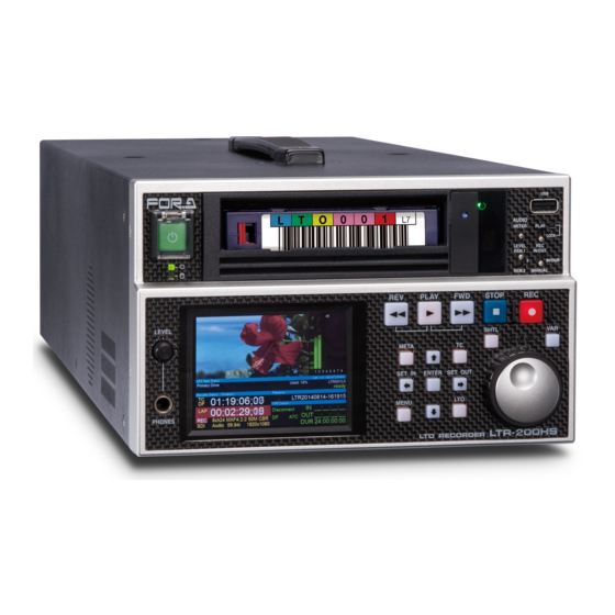
5. Panel Descriptions 5-1. Front Panel (3) (4) AUDIO METER PLAY LOCK LEVEL REM.1 IN/OUT IN/DUR REM.3 MANUAL PLAY STOP LEVEL SHTL META SET IN ENTER SET OUT MENU PHONES LTR-200HS LTO RECORDER (10) Name of Part Description POWER button When the POWER button is pressed, the power of the system is turned on, and the button lights up green. -
Page 67: Status Lights
5-1-1. Status Lights Name of part Description Blinks in green while data Operating light is being read from or written on the LTO tape. Blinks in amber when an Trouble light error has occurred. An error code is displayed here when an error has Single-character occurred. -
Page 68: Monitoring Screen
5-1-3. Monitoring Screen In the Monitoring screen, the preview images, audio level meter, time code, lap time, recording parameters (bit rate, resolution, frame rate, number of audio channels and number of audio bits), recording filenames, IN and OUT point TCs and DURATION are displayed. Left: playback mode;... -
Page 69: Decoding/Encoding Status
Item In Playback mode In Recording mode LTO status These indicate the LTO drive status. displays no tape The LTO tape is not mounted. prepare Now preparing to mount mounting Now mounting ready The LTO tape has been mounted, and data can be read or written. -
Page 70: Start And End Timecode Display
Item Description Input status Displays the input signal status. displays SDI (in recording mode) Indicates presence of input SDI signals. A blinking of “SDI” indicates an error or failure to recognize the input signal. LOCK (in playback Indicates that the output has been mode) synchronized with the genlock signal. -
Page 71: Recording And Playback Control Area
Item Description DF/NDF display Differentiation between drop frame mode and non-drop frame mode (*1) de pends on the input signal when the setting calls for the ancillary TC to be embedded. In the case of a fixed TC, the display depends on the setting in the Timecode (Rec) screen. -
Page 72: Menu Control Area
5-1-5. Menu Control Area Button In Playback mode In Recording mode META Displays the Metadata screen. When the button is pressed in the Metadata screen, any changes that have been made are canceled, and operation returns to the Monitoring screen. Displays the Timecode (Play) Displays the Timecode (Rec) screen. -
Page 73: Search Operation Area
5-1-6. Search Operation Area SHTL ③① ① Item In Playback mode In Recording mode SHTL Press this button to switch into shuttle mode. In shuttle mode, the SHTL button is lit. Press this button to switch into variable mode. In variable mode, the VAR button is lit. Jog dial Used to change settings with a... -
Page 74: Rear Panel
5-2. Rear Panel RS-422 TO EXTERNAL DRIVE AES IN AES OUT SDI IN GENLOCK IN Cooling fan SDI OUT (10) AC100-240V 50/60Hz IN MAINTENANCE GPI/ALARM (11) LAN1 LAN2 USB1 USB2 S/No. Serial Number Insert a USB cable connector with the USB symbol positioned on the left side Name of part Description... -
Page 75: Digital Audio Input/Output Area
5-2-1. Digital Audio Input/Output Area Name of part Description AES IN 1/2 AES digital audio signals are input here. When this connector is used, set Audio source in the Input Signal Settings screen to AES IN. AES IN 3/4 AES digital audio signals are input here. When this connector is used, set Audio source in the Input Signal Settings screen to AES IN. -
Page 76: Ltc Input/Output Area
5-2-3. LTC Input/Output Area Name of part Description LTC IN LTC signals are input here. When this connector is used, set LTC source in the Input Signal Settings screen to LTC IN. LTC OUT LTC signals are output from here. The same signals as the ATC (Ancillary Timecode) of the SDI output are always output. -
Page 77: Gpi/Alarm
*2: Refer to “GPI input circuit” below. *3: The maximum current supplied with a +5 V output is 200 mA. *4: Refer to “GPI output circuit” in the next page. Alarm output circuit LTR-200HS7 side Max: 30V Relay contact POW ALARM Closed when a malfunction... -
Page 78: Power Supply Area
GPI IN GPI input circuit LTR-200HS7 side Shorted with ON GPI IN1-3 RS-422 GPI output circuit LTR-200HS7 AES OUT GENLOCK IN Open collector output; allowable current of GPI OUT each pin: 20mA. 5-2-6. Power Supply Area AC100-240V 50/60Hz IN GPI/ALARM ①... -
Page 79: Troubleshooting
If the “LTO driver has a problem” message appears →Shutdown the unit following the procedure in section 2-3-2. “Turning the Power Off" and then restart the unit. (3) If the problem cannot be remedied, contact the FOR-A Service Center. ... - Page 80 If it is possible to mount the cartridge, return to normal operation. (6) If the problem cannot be remedied, contact the FOR-A Service Center. The input images are (1) If Playback mode is established, change to Recording mode.
- Page 81 (2) If “local” is displayed, there is nothing wrong with the connections, but it means that the VTR has not been set to REMOTE mode. Set the VTR to REMOTE mode. (3) If the problem cannot be remedied, contact the FOR-A Service Center. ...
- Page 82 Attention: It may take up to 10 minutes to reach the stage where nothing is displayed on the SCD in step 4. (3) If the problem cannot be remedied, contact the FOR-A Service Center. When the front panel When the front panel buttons cannot be operated, the power-off...
-
Page 83: Restrictions
7. Restrictions 7-1. Recording Details of restrictions Related section no. Recorded MXF files are written onto the LTO tapes as they are being recorded, 4-3-1 but writing may take some more time even after recording is completed. Proxy files are not written as they are being recorded but are written after MXF files have been written. - Page 84 Details of restrictions Related section no. The TC field in Encoder Status may be blank in some cases if time code is not 5-1-3-1 included in input. After changing from Playback to Recording mode or changing the format in Encoder Profile, if input signal is recorded consecutively, saving delay may occur once every 17 times and may require up to several minutes for saving.
-
Page 85: Playback
7-2. Playback Details of restrictions Related section no. Cache erase operations cannot be performed for an open file that is playing back. 4-3-1 To perform cache erase, switch the mode from playback to recording, and close the file. For the playback of MXF files, basically only files created on the LTR recorder are supported. -
Page 86: Supported Lto Tape
1MB or larger file-size thumbnails will not show in the File List. If you create thumbnails outside the LTR-200HS7, be sure to keep the file size smaller than 1 MB. When recording with some codecs, the timecode data is incremented continuously from the start timecode. -
Page 87: Specifications And Dimensions
8. Specifications and Dimensions 8-1. Specifications Video Formats HD: 1080/59.94i, 1080/50i, 720/59.94p, 720/50p Removable Storage LTO-5 / LTO-6 / LTO-7 (File system: IBM LTFS) Device *LTO-5 is reading only. Supported MXF [OP-1a (SMPTE RDD-9) ] Format HD: MPEG-2 Long GOP -50Mbps (CBR/4:2:2/422P@ML) Audio: 24bit, 8ch -35Mbps (CBR/4:2:0/MP@HL) - Page 88 Audio Output The maximum number of output channels varies according to MXF format and bitrate. Embedded Max. 8 ch (4 stereo pairs) (Group 1 and 2) 48 kHz, synchronous only AES/EBU 1.0 Vp-p, unbalanced, 75Ω, BNC x 2 (2 stereo pairs), 16/20/24-bit, 48 kHz Time Code Input Embedded...
-
Page 89: Proxy Video
8-2. Proxy Video 8-2-1. H.264 File Video Standard H.264 Baseline Profile Level 2.1 Resolution HD: 424 x 240 Frame rate NTSC: 29.97 fps, PAL: 25 fps Bit rate 900 kbps Audio Standard AAC LC Number of channels 2 ch Sampling rate 16-bit, 48 kHz Bit rate 96 kbps... -
Page 90: Lto-5 Basic Performance
8-3. LTO-5 Basic Performance Cartridge Size 105 (W) x 22 (H) x 102 (D) mm Capacity Approx. 1.5 TB (data area: 1425 GB / 1327 GiB) Recording capacity The following, values excluding ancillary data and proxy video files, are theoretical. Actual values may differ depending on LTO tape and head conditions. -
Page 91: External Dimensions
8-6. External Dimensions (All dimensions in mm.) RS-422 TO EXTERNAL DRIVE AES IN AES OUT SDI IN GENLOCK IN SDI OUT AC100-240V 50/60Hz IN MAINTENANCE GPI/ALARM LAN1 LAN2 USB1 USB2 S/No. - Page 92 Warning This equipment has been tested and found to comply with the limits for a Class A digital device, pursuant to Part 15 of FCC Rules. These limits are designed to provide reasonable protection against harmful interference when the equipment is operated in a commercial environment. This equipment generates, uses, and can radiate radio frequency energy and, if not installed and used in accordance with the instruction manual, may cause harmful interference to radio communications.
- Page 93 2 Executive Drive, Suite 670, Fort Lee Executive Park, Fort Lee, NJ 07024, USA Tel: +1 201 944 1120 Fax: +1 201 944 1132 FOR-A Corporation of America Distribution & Service Center 2400 N.E. Waldo Road, Gainesville, FL 32609, USA Tel: +1 352 371 1505...
Need help?
Do you have a question about the LTR-200HS7 and is the answer not in the manual?
Questions and answers