Table of Contents
Advertisement
Advertisement
Table of Contents

Summary of Contents for Western Scale AURORA 45
- Page 2 Information in this Installation / Technical Manual is subject to change without notice due to correction or enhancement. The information described in this manual is the property of Western Scale Co. Ltd. No part of this manual may be reproduced or retransmitted in any form, without the expressed written permission of Western Scale Co.
-
Page 3: Table Of Contents
TABLE OF CONTENTS INTRODUCTION ................................. 2 DISCLAIMER................................2 AURORA FEATURES ............................3 DISPLAY................................. 4 INSTALLATION ................................4 PRE-INSTALLATION ............................. 4 OPENING THE AURORA ENCLOSURE (UNMOUNTED)..................5 REMOVING THE ELECTRONICS CARRIAGE ..................... 5 MOUNTING INSTRUCTIONS ..........................6 OPENING THE AURORA ENCLOSURE (MOUNTED) ..................8 LOWERING THE ELECTRONICS PLATE ...................... -
Page 4: Introduction
INSTALLATION & TECHNICAL MANUAL INTRODUCTION The Aurora Remote Display Series is the latest development from Western, the company which first brought LED remote displays to the weighing industry in the 1980s. New technologies, materials, and construction methods have allowed a remarkable evolution in remote displays, making them more affordable, easier to read, and a vital part of any scale system. -
Page 5: Aurora Features
• Power Save Mode reduces power consumption during long periods of inactivity. MORE… • A ready to use, built-in traffic light (Aurora 45 SL model only). • Selectable brightness levels. • Built-in relay remotely controls traffic lights. • Built-in utility programs for axle weighing, traffic light control, etc. -
Page 6: Display
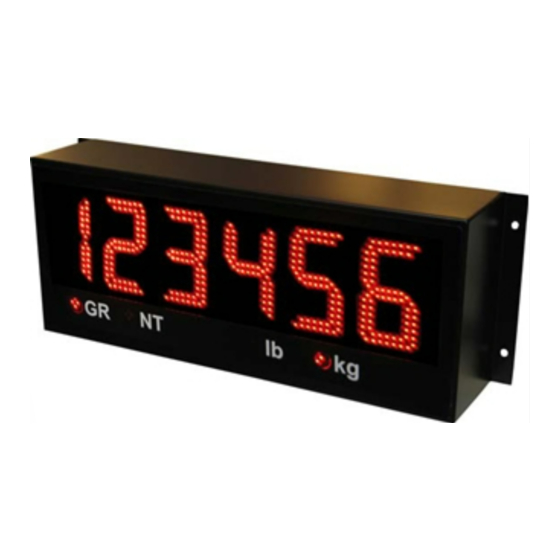
INSTALLATION & TECHNICAL MANUAL DISPLAY WEIGHT DISPLAY ANNUNCIATORS Fig. 1: Aurora 45 Display WEIGHT DISPLAY: 6 LED digits (7 segments). Up to 2 decimal places. ANNUNCIATORS: GR = Gross Weighing Mode NT = Net Weighing Mode Pounds kg = Kilograms... -
Page 7: Opening The Aurora Enclosure (Unmounted)
OPENING THE AURORA ENCLOSURE (UNMOUNTED) When opening an Aurora prior to mounting, place the unit top-down on a smooth, flat, surface. 2. Make sure the unit is disconnected from power. 3. Remove the captive screws from the bottom of the enclosure. 4. -
Page 8: Mounting Instructions
1. Inspect the installation site for properly grounded power. 2. Ensure that mounting structures (walls, pole brackets, etc.) will bear the weight of the display (Aurora 45: 20 lbs, Aurora 65 & 45SL: 32 lbs). 3. Allow proper clearance for lowering and removing the Electronics Carriage. - Page 9 Pole Mounting Bracket 1. Select appropriate height and fasten the small “C” bracket to the pole using the mounting clamps provided. 2. Fasten the larger “C” bracket to the small “C” bracket using the hardware provided. 3. Fasten the Aurora display to the Pole Mounting Bracket as outlined in the Mounting Instructions (See Fig.
-
Page 10: Opening The Aurora Enclosure (Mounted)
INSTALLATION & TECHNICAL MANUAL OPENING THE AURORA ENCLOSURE (MOUNTED) 1. Make sure the unit is disconnected from power. 2. Remove the captive screws from the bottom of the enclosure. 3. Slowly, guide the Electronics Carriage out of the Main Enclosure, being careful to avoid bending any LED leads. -
Page 11: Lowering The Electronics Plate
LOWERING THE ELECTRONICS PLATE 1. Remove the two (2) captive screws holding the Electronics Plate to the Electronics Carriage. 2. Slowly, allow the Electronics Plate to swing down, making access easier for wiring and service (As seen in Fig. 8). CAPTIVE SCREWS Fig. -
Page 12: Wiring
INSTALLATION & TECHNICAL MANUAL WIRING POWER WIRING Aurora Remote Displays are wired for power at the factory. The factory supplied power cable can be removed for direct AC wiring if necessary. CAUTION! HIGH VOLTAGE! Only trained personnel should attempt this procedure. ATTENTION! AC wiring must be terminated at the AC Power Terminal Block, not directly at the Power Supply board. -
Page 13: Communications Wiring
POWER WIRING (Continued) Fig. 9: Power Wiring COMMUNICATIONS WIRING All communications wiring terminates at the Controller board. Communications should be wired before applying power to the unit if possible. Communication Input Jumper A communications input type (RS 232, RS 422/485, or 20 mA Loop) must be selected by placing the jumper on the appropriate pins. -
Page 14: Rs 232 Daisy Chain
INSTALLATION & TECHNICAL MANUAL RS 232 Daisy Chain INDICATOR TO AURORA 1 TO AURORA 2 Etc… RS 422 Wiring 1. Set the Communication Input Jumper (JP 1) to RS485. 2. Terminate the indicator’s communication wires at the RS 485 terminal (J4). See table below: INDICATOR TO AURORA REMOTE DISPLAY... -
Page 15: 20 Ma Current Loop Wiring
20 mA Current Loop Wiring 1. Set the Communication Input Jumper (JP 1) to LOOP. 2. Terminate the indicator’s communication wires at the 20 mA Current Loop terminal (J5). See table below: INDICATOR TO AURORA REMOTE DISPLAY 20 mA TX + RECEIVE POSITIVE (RX +) 20 mA TX - RECEIVE NEGATIVE (RX -) -
Page 16: Start-Up
INSTALLATION & TECHNICAL MANUAL START-UP POWER UP • The Aurora has no ON/OFF button or switch. Plugging the unit into AC power will turn the unit ON. • Disconnecting AC power will turn the unit OFF. RESET BUTTON • The RESET button on the Controller board allows the Technician to cycle power on the unit without disconnecting/connecting AC power. -
Page 17: Diagnostic Indicator Lights
DIAGNOSTIC INDICATOR LIGHTS The Aurora has 3 diagnostic indicator lights located on the Controller board. Fig. 12: Indicator Lights STATUS Light: • The Aurora’s “heartbeat”. BLINKS when power is applied to the unit. • Regular blinking (Once per second) indicates that the Aurora has successfully learned a data string and is running properly. -
Page 18: Configuration & Options
INSTALLATION & TECHNICAL MANUAL CONFIGURATION & OPTIONS The Aurora uses two banks of Dip Switches on the Controller board (SW 3 & SW 4) to set-up the configuration and options. NOTE: Dip Switch settings take effect only after the Aurora has been reset (Cycle power directly or press the “RESET”... -
Page 19: Switch 5: Mirror Display Mode
Switch 5: Mirror Display Mode The Aurora’s digits may be mirrored for applications where the display is viewed from a vehicle’s rear-view or side-view mirrors. MIRROR DISPLAY MODE SWITCH 5 OFF (Default – Digits normal) ON (Digits mirrored) Switch 6: Start-up Auto-Learn On power up, the Aurora automatically enters Auto-Learn Mode, analyzing the serial communications and string type. -
Page 20: Options Switches
INSTALLATION & TECHNICAL MANUAL OPTIONS SWITCHES The “OPTIONS” bank of dip switches (SW 4) is for the following features: Switches 1, 2, 3, & 4: Utility Program Select The Aurora has built-in utility programs that run in conjunction with the normal display functions. -
Page 21: Switch 6: Leading Zeros
Switch 6: Leading Zeros In some cases, the scale indicator may transmit leading zeros in the output string. If leading zeros are NOT required, they may be suppressed. The Aurora will automatically remove the leading zeros and replace them with blank spaces on the display. -
Page 22: Traffic Light Control
INSTALLATION & TECHNICAL MANUAL TRAFFIC LIGHT CONTROL EXTERNAL TRAFFIC LIGHTS (Aurora 45 & 65) External traffic lights can be switched by the Aurora’s built-in relay. 1. Wire the traffic light to the Stop Light terminal (J7) on the Controller board:... -
Page 23: Built-In Traffic Light
BUILT-IN TRAFFIC LIGHT (Aurora 45 SL Only) The built-in traffic light may be controlled by remote switch, the pre-installed utility programs, or serial commands (in Command Mode only). Remote Switch 1. Wire remote switches to the Stop Light Remote Switch terminal (J2) on the back of the Stop Light Display board. -
Page 24: Aurora Utility Programs
INSTALLATION & TECHNICAL MANUAL AURORA UTILITY PROGRAMS The Aurora signboard has several auxiliary functions that may be activated via the OPTIONS dipswitches on the controller board. PROGRAM SW 1 SW 2 SW 3 SW 4 1 – NORMAL Mode (No program) 2 –... - Page 25 Program 4: COMMAND MODE All Aurora displays can be setup to receive commands directly from the scale system or PC. Supported commands include transmitting weights, basic alphanumeric messaging, stoplight relay control, and additional display functions. Command mode disables Auto-Learn and fixes communications at 9600-N-8-1. The Aurora looks only for specific commands sent by the indicator or scale controller.
- Page 26 INSTALLATION & TECHNICAL MANUAL Control Commands Control commands are single ASCII characters (followed by <CR>) that are transmitted to the Aurora to control additional features such as the built-in traffic light (Aurora 45 SL) and the traffic light relay. CONTROL COMMAND...
- Page 27 Multi-Drop addressing Aurora displays using Multi-drop must be in Command Mode. The Multi-drop address (0 to 3) is set using SW8 and SW9 on the CONFIG dipswitch bank (See page 17). When using Multi-drop, the Aurora will only respond after it has been selected. To select the display, transmit a “#”...
-
Page 28: Wireless Set-Up
INSTALLATION & TECHNICAL MANUAL WIRELESS SET-UP AURORA REMOTE DISPLAY 1. With factory installed Radio Modules, the external antenna must be connected to the SMA terminal on the bottom of the Electronics Carriage. The Aurora is ready to receive radio signals. 2. -
Page 29: Indicator & Basestation
INDICATOR & BASESTATION 1. Connect the BaseStation to scale indicator (or other appropriate device) using the serial interface cable provided. Interface cables are Beldon Type 8723. See table for pin outs: INDICATOR 9 PIN (MALE) CONNECTOR TRANSMIT (TX) PIN 3 RECEIVE (RX) PIN 2 SIGNAL GROUND (GND) -
Page 30: Basestation Set-Up
INSTALLATION & TECHNICAL MANUAL BASESTATION SET-UP NOTE: In most cases, the default settings will work well. No BaseStation set-up will be required. To configure the BaseStation settings, a PC with the MaxStream X-CTU software (included) is required. 1. Install MaxStream X-CTU software on PC. 2. -
Page 31: Select The Radio Channel
BASESTATION SET-UP (Continued) 5. Click on the MODEM CONFIGURATION tab. 6. Select the appropriate radio (X09-009) from the MODEM pull-down menu. 7. Click the READ PARAMETERS button. The BaseStation will send its current set-up information to the PC. Select the Radio Channel 1. -
Page 32: Set The Baud Rate
INSTALLATION & TECHNICAL MANUAL Set the Baud Rate 1. Scroll down to the “Serial Interfacing Options”. 2. Click on the “Baud Rate” parameter. 3. Select the desired Baud Rate from the pull-down menu. This Baud Rate must match the indicator’s Baud Rate. 4. -
Page 33: Troubleshooting & Error Messages
TROUBLESHOOTING & ERROR MESSAGES • Verify AC power source (Outlets, breakers, Unit won’t power up: etc.) • Check Terminal Block connections inside the Main Enclosure. • Verify power wiring from Terminal Block to the Power Supply board. • Check fuse on Power Supply board. •... - Page 34 INSTALLATION & TECHNICAL MANUAL • Data String Auto-Learn has failed. Display reads “Error 2”. • Verify the correct terminal (RS 232, 422/485, 20 mA) is being used and check wiring. • Verify that the Communications “Input Select” jumper is properly set. •...
Need help?
Do you have a question about the AURORA 45 and is the answer not in the manual?
Questions and answers