Advertisement
Quick Links
Advertisement

Summary of Contents for DAYLIFF ULTRASUN UFS
- Page 1 ULTRASUN UFS Flatplate Solar Systems Installation & Operating Manual...
- Page 3 INDEX SPECIFICATIONS 2. EQUIPMENT SPECIFICATIONS 3. WARNINGS & SYMBOLS 4. SITING 5. INSTALLATION 6. SYSTEM COMMISSIONING 7. USAGE 8. MAINTENANCE 9. TROUBLE SHOOTING 10. TERMS OF WARRANTY © Davis & Shirtliff Ltd 2020 Contents herein are not warranted...
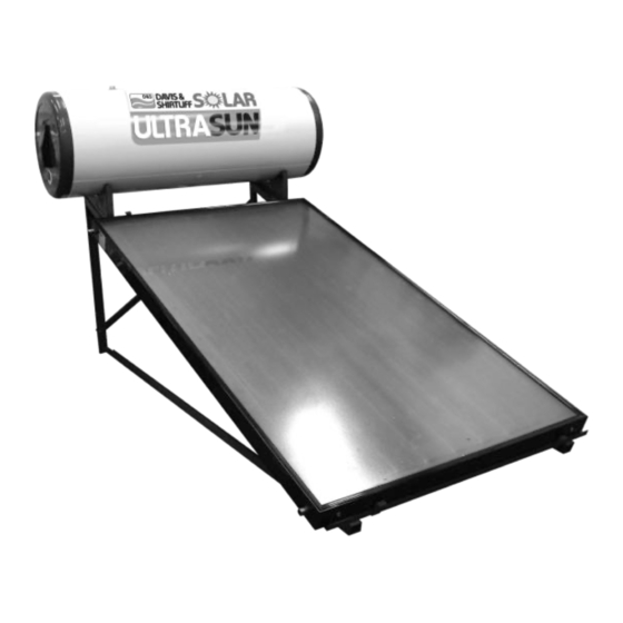
- Page 4 • Galvanised mounting frame Ultrasun UFS Flatplate Systems are available in three sizes to suit domestic and small scale institutional applications. They are effective and robust products designed for many years of trouble free operation with a 5 year guarantee to demonstrate product quality.
- Page 5 DESIGN FEATURES Direct Tank Solar Collector 1. Steel outside casing coated by electrostatic 1. Copper Aluminum fin absorbing plate powder coating baked at 220 C to protect the 2. High Transmittance Glass tank from outdoor conditions and UV rays 3. Polyester Fibre Insulation 2.
- Page 6 Open-Loop (Direct) Systems Open - Loop Enameled Storage Tank Security Valve 8 Bars Nipple Filter One-way Water Valve Outlet Cold Water Inlet T Nipple I n s u l a t e d Solar Collector Solar Collector copper pipe Plug SPECIFICATIONS UFS 150D UFS 200D...
- Page 7 NOTE Maximum heating output is based on average irradiation levels of 6000W/m /day prevailing in September- March and minimum Heating output is basedon average irradiation levels of 4000W/m /day prevailing in June/July and are for indicative purposes only. 3. WARNING AND SYMBOLS The installation of the solar system must be in accordance with the relevant requirements of the local authority building regulations as well as regulations for the prevention of...
- Page 8 Steam can escape from the expansion relief valve of the solar pump unit if the system is shut down. To avoid injuries an expansion relief valve must be connected to a collecting container with a hose line In order to ensure a seamless operation of the product, the safety valve should be cleaned periodically and checked for proper functions.
- Page 9 SOUTH OF THE EQUATOR 5. INSTALLATION Ultrasun UFS solar heaters are provided with drilled frames incorporating a support cross bar. On roofs the preferable mounting arrangement is by means of hooks affixed to the cross bar and secured to an appropriate mounting point on the roof beams. Suspension from the hooks is generally sufficient and fixed location is not necessary.
- Page 10 The units can be installed using a gravity system or pressurised supply. Pressurised systems are preferable as they give higher line pressures up to a maximum of 3 Bar. Note that in the case of pressurised supply hot and cold lines must be pressurised at the same pressure to ensure even temperature control.
- Page 11 The various installations are shown below: Flat roof Installation Pitch Installation Single Panel Installation Pitch Roof Bracket Assembly Step 1 Fit the top part of the solar tank bracket to channel 3 using M8 x 25 screws as shown.
- Page 12 Step 2 Select the holes in the angled section that are required for the specific installation. It is suggested that the holes be marked according to the specific type of installation required. Two types of angled sections are provided, a set for a single panel installation and a set for a double panel installation.
- Page 13 Step 4 Select which slotted holes the bottom angled section should be bolted onto. The selection should be based on the size of the solar collectors supplied. Two sizes are available: 2.0m² Approximately 2000 mm in length Ÿ 2.4m² Approximately 2000 mm in length Ÿ...
- Page 14 Step 6 Remove the tank feet supplied as shown below: Step 7 Fit the tank to the completed bracket frame as shown below on both sides. This step is to confirm that the two longitudinal channel beams are appropriately spaced to accommodate the tank.
- Page 15 Step 8 Fit the collectors to the bracket by placing them between the angled sections as shown below. Adjust the bottom angled section position by means of the slotted holes in order to fit the panel/s closely. Fasten the panels through the 6mm holes by means of the M5 x 16 self drilling screws.
- Page 16 The strips can be used to fit the system to the battens of the roof to provide additional support. Please note that longitudinal channel should coincide with or be as closely located to the rafters of the roof structure as possible. The strip fastening method is depicted below in section view.
- Page 17 Fig 1 Vacuum Anti-siphon Loop Breakers T&P Safety Hot Water Outlet (Metallic) Outlet Hot Water T&P Safety From Valve Panel 150 OR 200L 300L HOT HOT WATER WATER CYLINDER CYLINDER Cold Water From Cylinder Single Panel Double Panel 2100 1000/1400 Mains Pressure Pressure Control Valve Stopcock...
- Page 18 Step 12 Turn the structure upside down and fasten channel 2 to the top part of channel 3 using M8 x 65 screws and long spacer tubes as shown below on both sides: Step 13 Fit the two longitudinal channels using M8 x 65 screws and long spacer tubes on both sides as shown below: Step 14 Fit channel 4 to channel 3 using M8 x 65 screws and long spacer tubes on both sides as...
- Page 19 Step 15 Mount channels 1, 2 and 4 together using M8 x 65 screws and long spacer tube on both sides as shown below: Step 16 Two types of braces are included in the kit. Short braces are used for 150 and 200 litre installations and long braces for 300 litre installations.
- Page 20 200 Litre Tank 300 Litre Tank Step 17 Fit the brace ends using M8 x 25 screws on both sides as shown below: Step 18 Fasten the braces' centre holes using M8 x 25 screws and short spacer tube as shown below:...
- Page 21 Step 19 Remove the tank feet supplied as shown below: Step 20 Fit the tank to the completed bracket frame as shown below on both sides. This step is to confirm that the two channel 3 beams are appropriately spaced to accommodate the tank.
- Page 22 Step 21 Fit the panel/s to the assembled frame by placing them between the angled sections as shown below. Adjust the bottom angled section position by means of the slotted holes in order to fit the panel/s closely. Fasten the panels through the 6mm holes by means of the M5 x 16 self drilling screws.
- Page 23 ROOF SEAL This is a bonded seal to the roof surface which normally has a metal surround that can be easily manipulated to fit the profile of roof clading. Before applying the seal, a 25mm hole has to be drilled in the roof cladding. For metal roofs a hole saw for metal can be used while a core drill of 25mm suitable for concrete can be used on tiled roofs.
- Page 24 Electrical Heater 230V (3000W) 50Hz TRR 3*2, 5mm Feeding Cable BLUE Thermostat BROWN YELLOW & GREEN 6. SYSTEM COMMISSIONING a) Direct Systems On installation or after service it is important that the system is primed. This is carried out by first opening the incoming feed followed by the bleed cock and then observing when all air is expended from the bleed outlet.
- Page 25 9. TROUBLE SHOOTING DIRECT SYSTEMS PROBLEM POSSIBLE CAUSE SOLUTION Rotation use or replace with a larger High hot water usage at night system Incorporate complimentary electric Prevailing weather conditions heater to be used when irradiation is low Non-operation of electric booster Replace the electric heater Ensure tank connections are higher Air locks in the collectors...
- Page 26 PROBLEM POSSIBLE CAUSE SOLUTION Pressure above 3 bar Lift valve hand lever and reset valve Use a pressure tank to regulate and High mains pressure reduce pressure levels Water discharge Replace the valve if discharge Pressure is below specification settings from pressure continues release valve...
- Page 27 10. TERMS OF WARRANTY i) General Liability • In lieu of any warranty, condition or liability implied by law, the liability of Dayliff (hereafter called the Distributor) in respect of any defect or failure of equipment supplied is limited to making good by replacement or repair (at the Distributor’s discretion) defects which under proper use appear therein and...
- Page 28 INS456A-07/20...
Need help?
Do you have a question about the ULTRASUN UFS and is the answer not in the manual?
Questions and answers