
Summary of Contents for Cordes CDNA-041G
- Page 1 Operator Manual For the CDNA-041G Network Adapter Rev A Date: 5/19/2020 CorDES Proprietary Information...
-
Page 2: Table Of Contents
Mounting and Making Connections .................11 Power On ........................12 Configuring the ECU Data Interfaces ..............12 Configuration for Operation ................. 13 Installing and Launching the HMI Application ............13 CDNA-041G Windows Overview ................13 5.2.1 Main Window .......................14 5.2.2 Configuring the Remote Management Interface ...........14 5.2.3... - Page 3 Table 3-2 Rear Panel Connections ...................10 Table 4-1 CNDA-041G to ECU Connections ................11 Table 4-2 CDNA-041G Default mapping of Front Panel PHY to Rear Panel Connectors ..12 Table 4-3 ECU Data Interface Settings ..................13 Table 5-1 Hardware and Software Requirements ..............13 Table 5-2 CDNA OP Modes ......................18...
-
Page 4: Change Page Summary
CHANGE PAGE SUMMARY REVISION DATE CHANGES 12/3/2019 Original Release 5/19/2020 Update to incorporate UDP fixed bypass mode & Python Management API scripted interface CorDES Proprietary Information... -
Page 5: Overview
The front panel faceplate is easily removed with five thumb screws allowing the ECUs to slide in through the front of the chassis for easy installation. The CDNA-041G provides access to all the ECU data and management interfaces via rear panel cut outs, for a total of 4 Channels. Redundant hot-swappable autosensing power supplies provide AC to DC conversion. -
Page 6: Supplied Accessories
Two (2) NEMA 5-15P to IEC-60320-C13 A/C Power Cords Two (2) ECU power cables 1.4 Optional Accessories The user of the CDNA-041G should provide the following items for operation. These items are available for order as optional accessories at time of purchase. Item Part Number... -
Page 7: Figure 2 Virtual Network Device Stack
Figure 2 Virtual Network Device Stack A CDNA Dataplane Application Programming Interface (API) is available to support CDNA compatible packet generation as defined in the CDNA-041G Data Plane Interface Control Document. A customized CDNA header or fixed bypass header (described in Reference A) enables packet level header bypass (Figure 3). -
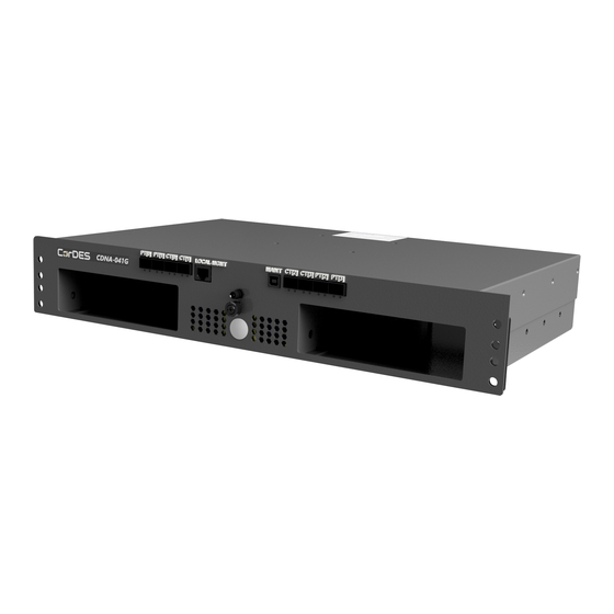
Page 8: Interfaces And Connections
The front panel of the CDNA (Figure 4 and Figure 5) contains the power switch, indicators and connections to configure the unit for operation. Table 3-1 lists and describes functions of the connections on the front panel. Figure 4 Front View of CDNA-041G CorDES Proprietary Information... -
Page 9: Rear Panel
Figure 5: Front Panel with Port Labels of CDNA-041G Connection Connector Function Name ON/OFF Enables and disables prime power to the unit. Integrated LED provided visual indication of power Remote RJ-45 Plug 10/100 (Base-T) Remote management interface port to Management... -
Page 10: Installation
The CDNA-041G is shipped in reusable packaging materials. Save these packaging materials for future use in case you need to ship the CDNA-041G. Save this document along with the packaging materials for future reference. The CDNA-041G is shipped in a single box which contains the chassis, faceplate and power cables. -
Page 11: Mounting And Making Connections
Inspect the shipping container for signs of damage during shipping, storage, or handling. Open the container and carefully remove the CDNA-041G from the box. Inspect the unit for any external damage; this includes checking the power switches, connectors and mounting tabs. -
Page 12: Power On
CT[1] 64007 CT[3] Table 4-2 CDNA-041G Default mapping of Front Panel PHY to Rear Panel Connectors • NOTE: *Default IP.Port# can be changed by HMI or CLI. The Front Panel has 4x PHY ports, each with a unique programmable IP address. Each PHY has two IP Port #’s associated with it (programmable) to allow mapping of two logical data... -
Page 13: Configuration For Operation
5 CONFIGURATION FOR OPERATION This section provides detailed information about the CDNA remote management Human to Machine Interface (HMI) application used to configure and view status of the CDNA-041G from a workstation running Microsoft ® Windows 10 ® operating system. The management application connects to the CNDA through an IPv4 Internet protocol (TCP/IP) Ethernet connection over the unit’s remote management connector. -
Page 14: Main Window
To configure the remote management interface, enter the desire Host IPv4 address and click “Submit & Apply”. NOTE the Host Port should always be 10000 for the CDNA-041G. The first time you enter the IP address you need to also click “Apply & Restart” as the IP address is stored locally to the configuration file. -
Page 15: Hmi Network Connection Status To Remote Cdna Device
DHCP issues will be resolved automatically. 5.2.4 Configuring the Remote CDNA From the initial page, click the “DEVICE SETTINGS” in the left column. This will take you to the page to modify the remote CDNA Settings as shown in Figure 10. CorDES Proprietary Information... -
Page 16: Figure 10 Global Device Settings
At this time these parameters are not used and can be ignored. On this page there are 5 sections that are described below to modify each of the operational parameters. Some of these parameters must be set to match the operational configuration of the embedded GOE: CorDES Proprietary Information... -
Page 17: Configuring The Plain Text (Pt) And Cipher Text (Ct) Interfaces Device Settings
To configure the PT and CT data ports, navigate to the Device Settings tab. Enter the IPv4 address, NetMask and default Gateway information as shown in Figure 11 and Figure 12 . The NRZ Mode is hard coded to NRZ-L. Figure 11 Configuring PT Data Interfaces CorDES Proprietary Information... -
Page 18: Configuring The Op Mode And Encrypt Mode
OP Modes-- GCM and CTR/ECB: These modes configure the CDNA for UDP networking. If selected, the window will dynamically update and display a “Channel #n Send To Address” field as shown in Figure 13. Enter the destination IP address to send the output data packets. CorDES Proprietary Information... -
Page 19: Multicast Configuration
IP address is desired, click the “Enable” checkbox for the desired channel, enter the IP address and click Submit. Up selecting Submit the second IP address is automatically installed. To permanently save the update, click “Apply and Restart” at the top of the page. CorDES Proprietary Information... -
Page 20: Viewing The Cdna Link Status And Packet Statistics
Figure 15. A brief explanation of each parameter is provided in Table 5-3 below. The “Clear Counters” button can be clicked at any time to reset the packet counters. This has no effect on operational traffic flow. CorDES Proprietary Information... -
Page 21: Packet Loss & Debug
Future use. Timeouts This Counter is incremented for any packet send from the CDNA-041G to the embedded GOE that is not responded to. The various reasons are that the GOE did not recognize the GCM header, the GCM packet has invalid integrity, the VCC is invalid (in vehicle sim mode), or the GOE is not ready for data. -
Page 22: Maintenance
Do not place objects on top of the unit. 7 PARTS INFORMATION The commercial AC power supplies in the CDNA-041G are field replaceable. If the unit is out of warranty replacement part for the power supply may be purchased from the power supply manufacture (3Y Power Technology). -
Page 23: Warranty Information
CorDES will provide return instructions to the customer. Once the equipment is received, CORDES will inspect the equipment to determine the cause and extent of the defect and if the defect is determined to be covered under this Warranty. CorDES will correct such defects by repair, modification, or replacement at its option without charge. -
Page 24: Errata
CDNA- 5/19/2020 On the HMI it is the NRZ mode setting is not OPEN DR-0003 functional. The mode is defaulted to NRZ-L. The NRZ-M mode selection is possible from the remote management CLI API. CorDES Proprietary Information... -
Page 25: Appendix A. Example Tcp/Ip Data Interface Configuration
(linux, windows, etc) connect to the CDNA socket servers and send or receive CDNA formatted packets. The CDNA packets are formed by using the included API methods that take raw data, or preformatted GOE data, and add a CDNA header to the information. CorDES Proprietary Information... -
Page 26: Appendix B. Example Udp/Ip Data Interface Configuration
Bypass header to the CT[1] at IP:PORT 169.254.100.102:64004. Data is decrypted, and bypass data is passed through internally to the PT[1] channel. The PT[1] channel is set to multicast, so it sends the output encrypted UDP/IP with fixed 20B Bypass to the two programmed destinations UDP servers at IP: 169.254.100.205:64001, and 169.254.100.206:64001 respectively. CorDES Proprietary Information... -
Page 27: Figure 16 Udp/Ip W/Fixed 20B Bypass Header Example
Default IP addresses and Ports are shown. All are configurable via HMI • Example is only showing 2x Channels configured for UDP/IP. The other 2x Channels may also be configured for UDP/IP or TCP/IP independantly. Figure 16 UDP/IP w/Fixed 20B Bypass Header Example CorDES Proprietary Information... -
Page 28: Appendix C. Remote Management Application Prgramming Interface
Command authentication is currently not required. Command Messages: This table enumerates the command message methods and parameters required for the CDNA-041G. Each command is read and processed by the unit and returns a 1 on success and 0 on failure. - Page 29 Command device to set the port to Send & Receive to/from for CT Channels[2]. Value=Desired port number <int> setCTCH2_port(value) Command device to set the port to Send & Receive to/from for CT Channels[3]. Value=Desired port number <int> setCTCH3_port(value) CorDES Proprietary Information...
- Page 30 Command device to set the optional 2nd (multicast) IP Address to Send to for Channel[2]. setCH2_multicastIP(address) address= Desired IP address in dot notation <string> Command device to set the optional 2nd (multicast) IP Address to Send to for Channel[3]. setCH3_multicastIP(address) address= Desired IP address in dot notation <string> CorDES Proprietary Information...
- Page 31 Sends a request to retrieve the full status from the device configuration. requestDeviceStatus() Returns status response messages STS-0005 and STS-0006 connects the CDNA Python Class via TCP/IP to the management IP address connectToCDNA(address) specified closeConnection() closes the CDNA TCP/IP management socket connection. CorDES Proprietary Information...
Need help?
Do you have a question about the CDNA-041G and is the answer not in the manual?
Questions and answers