Advertisement
Quick Links
Advertisement

Related Manuals for RPI NATURALIS 01

Summary of Contents for RPI NATURALIS 01
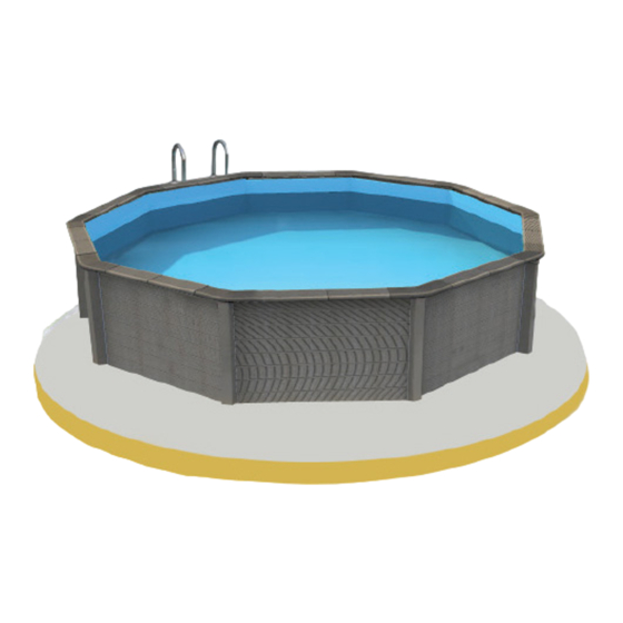
- Page 1 NATURALIS DECAGONAL 1.40 4,55 x 4,55 m A product of RP INDUSTRIES ®...
- Page 2 ® CONCRETE SWIMMING POOL, WOOD APPEARANCE INTRODUCTION You have just bought your Naturalis swimming pool. Thank you for your choice and PLEASE READ the trust you deposit on our product. We recommend that you read carefully these CAREFULLY AND instructions, follow them step by step, understand the instructions very well and take KEEP FOR FUTURE into account the advice and recommendations transmitted.
-
Page 3: Safety Warnings
Safety warnings It’s required to predict a special differential protective device for pools on the electric power of the pump according to legal and technical norms. The minimum distance between the pump and the pool must be at least 3,50mt, to prevent electrical shock. -
Page 4: Necessary Tools For Installation
DECAGONAL 4,55 x 4,55 m 62.50 cm Excavation 62.50 cm Concrete slab Inside Outside Water Height Depth Liner Filtration Weight Widht Lenght . Widht Lenght . Volume water (m) (Kg) 4,55 4,55 5,35 5,35 1,40 18,83 1,22 2 178 Solid Liner Cartridge Bleu Pâle 12 m... - Page 5 Ladder Kit composition for Naturalis 01 120x IMPORTANT: The ladder can not be used for other purposes. Maximum authorized weight:150 kg SUMMARY 1-Implantation 2-Excavation work 3-Concrete slab 4-Marking the layout of the pool 5-Fixing of pillars and steel base panel 6-Setting up the aluminum profile 7-Setting up Beam nº1...
- Page 6 Implantation IMPORTANT: Before beginning the installation, read carefully these instructions. Any installation, which is not made according to these instructions, will cancel the warranty. The choice of the pool localization is essential because it affects not only the reliability of the pool but also the comfort of utilization.
-
Page 7: Concrete Slab
Escavation work Begin to evacuate the land inside the circle, 62.50 cm deep according to the highest point. Once complete, check the level of the ground and put inside the welded metal mesh E300. 62.50 cm ATTENTION: The recommendations for partially or totally underground pools are valid for an installation on a dry field, without humidity. - Page 8 Marking the layout of the pool IMPORTANT: The assembly of the pool should be performed after complete drying of the concrete slab (2/3 weeks). Dimensions shown are interior dimensions. Before assembling, proceed to clean the slab to eliminate all kinds of impurities (sand, twigs, leaves, etc). The slab should be smooth without irregularities and properly leveled to allow the correct assembly of the pool.
- Page 9 Fastening the pillars and the base structure To obtain the position of the remaining pillars, install the base structure panels. Install the two panels between the A and C pillars for the location of the intermediate pillar. Do the same for the location of intermediate pillars between D/B, B/E and F/A. Fasten two screws in the pre-defined drilling and proceed Repeat to get the shape of the pool.
- Page 10 Fastening the pillars and the base structure ATTENTION: Before proceeding to the final establishment of the pillars to the concrete slab must verify the dimensions and the leveling of the structure as indicated. Points A, B, C, D, E, and F define the location of the first angle pillars. Angle Pillar Base structure panel After performing the positioning of the pillars...
- Page 11 Fastening the pillars and the base structure Fixation of the pillars Drill concrete with a drill, using the existing hole in the base of the pillar. Repeat for the structure. Then secure the pillar to the slab using the steel anchors provided in the kit. Fixing the base structure Using the same method of fixing pillars, fix the panels of the base structure.
- Page 12 Placement and fixing of aluminum profile IMPORTANT: Before the placement of the aluminum profile, you should apply a Developed to allow the fitting of the first row of wall platters, the aluminum profile bead of silicone to the top of the base frame rests on top of the base structure panels.
- Page 13 Placement of beam n.º 1 ATTENTION: For the placing of the beams, it is mandatory to respect the numbering of the parts. The platters are numbered as shown in the photo. BEAM N.º 1 (1st row) Nº 3 Nº 2 Nº...
- Page 14 Placement of beam n.º 1 During the placement of the beam, ensure that this is perfectly leveled. Place the first row of beams, formed by beam n.º 1, around the perimeter of the pool. Once placed the first row of beams check that they are correctly fitted so that it can ensure a perfect...
- Page 15 Placement of beam n.º 2 BEAM N.º 2 (2nd row) Nº 3 Nº 2 Nº 2 Nº 2 Nº 2 Nº 2 Nº 1 Base Structure Panel Beam n.º 2 ATTENTION: Before placing the sleepers, apply a silicone cord, as indicated for the first row (on the top of the sleepers).
- Page 16 Placement of beam n.º 2 IMPORTANT: You must apply among each slat a bead of silicon in the whole length in order to fix and secure a perfect stability of the whole structure. At each end, you must also apply a dot of silicon between the beam and the aluminum profile.
- Page 17 Placement of beam n.º 2 BEAM N.º 2 (from 3rd to 6ªth row) Nº 3 Nº 2 Nº 2 Nº 2 Nº 2 Nº 2 Nº 1 Base Structure Panel Beam n.º 2 The beam n.º 2 is intended to build the wall of the pool from the 2nd to the 6th row. The next chapter will deal with the placement of the panel where the outlet nozzle and the skimfilter will be installed.
- Page 18 Placement of the beam n.º 4 BEAM N.º 4 (OUTLET NOZZLE) Nº 5 Nº 4 Nº 2 Nº 2 Nº 1 Base Structure Panel Panneau A pour mur d’ équipements Beam n.º 4 The beam n.º 4 is for fixing the outlet nozzle (and, optionally, the projector) it should be in the 4th row.
- Page 19 Placement of beam n.º 3 BEAM N.º 3 (7th row) Nº 3 Nº 2 Nº 2 Nº 2 Nº 2 Nº 2 Nº 1 Base Structure Panel Beam n.º 3 The beams n.º 3 are intended to be placed in the last row of the pool wall (except for the skimmer wall).
- Page 20 Placement of beam n.º 5 and panel skimfiltre BEAM N.º 5 AND PANEL SKIMFILTRE Nº 5 Nº 4 Nº 2 Nº 2 Nº 1 Beam n.º 5 Beam n.º 5 Panel skimfiltre The two beams are placed on each side of skimfiltre, occupying the space of the 5th to the 7th row and are identified with n.º...
- Page 21 Placement of coping supports The steel supports are fixed with the nuts and bolts supplied in the kit (using appropriate tools). IMPORTANT: Decide the location of the stairs for the fixation of holders.
- Page 22 Placement of PVC HUNG profile for liner At this stage, you will have place the PVC liner profile, as shown in the figures. Start by applying a bead of silicon on the coping metal support on the inside edge of the pool. Using a drill machine and a steel drill of 3,5mm, make a hole every 20 cm, then put a bead of silicone and finally fix definitively the profile to the metallic support with the adequate screws.
- Page 23 Fixation of the protective steel panel The fixation of the steel panel is initiated by the skimmer wall. Place two steel panels making their sides overlap by approximately 1.5 cm. Apply the self-tapping screws at 3 points in the middle of the pillar, as shown in the photograph, and screw the panels. Repeat this process for all panels.
- Page 24 Fixation of the protective steel panel Placing the aluminum tape Once you have screwed all steel panels, apply the aluminum adhesive tape to hide the screw head (1). Apply aluminum tape between the steel panels and coping metal support parts (2), also on the junction of the steel panels and the base structure panels (3).
- Page 25 Installation of the embeded parts Placement of the skimfiltre The Skimfiltre is installed on the metal panel cut out for that purpose. In order to facilitate transport and placement, Skimfiltre is presented in two parts. The bottom part n.º 2 is placed after the attachment of the upper wall n.º 1. To fit the two parts put glue provided with SKIMFILTRE on part n.º...
- Page 26 Installation of the embeded parts Placement of the outlet nozzle The outlet nozzle is placed on the inside of the pool and with its screwed side facing the outside (1). The outlet nozzle is placed in the hole conceived for this purpose. By the external side, tighten the nut (2).
- Page 27 Pump and Hydraulic system connection IMPORTANTE: It is essential that the filtering system is in conformity to standard C 15-100, which requires that all electrical equipment located less than 3.5 m of the pool must be supplied with low voltage: 12V and all electrically powered device 220V must be located more than 3.5 m from the pool or indoors.
- Page 28 Pump and Hydraulic system connection CONNECTION OF THE OUTLET NOZZLE TO THE PUMP Follow the same indications as for the Skimfiltre. CONNECTION OF THE PUMP ATTENTION: The pump should be located more than 3.5 m from the pool or in an enclosed area. After having made the connection of all accessories to the pump, refer to professional service to make the...
- Page 29 Landfill around the pool Landfill 52.50 cm 52.50 cm Then perform the landfill until the steel base frame is completely covered (approx. 52.50 cm). En suite, effectuer le remblai au même temps que le remplissage de la piscine. Vous devez laisser 10 cm pour une dalle de propreté au niveau de la margelle...
- Page 30 Installation of the Geotextile carpet Proceed to the placement of the different parts and perform the necessary cuts in geotextile carpet to obtain the shape and dimension corresponding to the pool. IMPORTANT: Clean the bottom of the pool before proceeding to carpet placement. Afterward, put the different pieces, properly tensioned at the bottom of the pool without making it overlap, and finish with the application of tape over the joints of the different elements.
- Page 31 Placement of the liner ATTENTION: Prior to installing the liner, you must put the joints of the Skimfiltre and outlet nozzle. Verify that all joint holes are properly aligned with the Skimfiltre and outlet nozzle. IMPORTANT: An outside temperature of at least 20 degrees is necessary for the placement of the liner. We recommend that you remove your shoes before entering the pool and performing the placement of the liner...
- Page 32 Placement of the liner Unpack the liner inside the pool and unfold from the center toward the walls. Place an angle of the liner ahead of an angle of the structure and repeat the same operation across the pool. Insert horizontally the lip of the liner in the PVC anchorage support.
- Page 33 Placement of sealing rings After installing the liner and filling the pool up to 30 cm from the middle of the mouth of the skimmer, you should locate the previously placed joints on the outlet nozzle and Skimfiltre. Then, overlap the joint and the flange of the parts and make the first hole, screwing the first screw. Once the second screw is placed all the other holes will be in the right position.
- Page 34 Placing the coping After the filling of the pool coping is fixed with the silicon supplied in a kit. The coping is made of two types of different elements: straight and angle coping. The straight copings are applied on the straight parts of the pool and the angle copings on the corners. IMPORTANT: First, place all the angle copings without fixing them.
- Page 35 Mounting of stainless steel ladder Following the instructions provided with the stainless steel ladder, proceed to the assembly and fixing it in the proper place, indicated for such. After fixing the indoor/outdoor stainless ladder the pool is ready for the first baths. ATTENTION: For an above ground pool, remove the outside ladder after each use of the pool.
-
Page 36: Filtration Time
STARTING THE FILTRATION After you have finished filling the pool, run the filtration system. ATTENTION: Make sure all joints and connections are tight, that the water level is sufficient and that the pump is connected to an electrical panel protected with a circuit breaker 30 mA (we recommend the use of a professional for this job). - Page 37 CLEANING THE POOL AND THE WATER LINE In the high season, it is imperative to aspire to the pool at least once every fifteen days. You should connect vacuum tube to the Skimfilre, then switching on the pump and vacuum. Finished vacuuming, we recommend cleaning the cartridge.
-
Page 38: Water Treatment
WATER TREATMENT No matter what filtration system used, you have to treat chemically the water of the pool in order to destroy bacterias, microorganisms and to avoid the algae developing. Several sterilization products can be used, like chlorine, bromine, oxygen, salt electrolyzer or others. The most usual treatment is the chlorine. -
Page 39: Special Cases
SPECIAL CASES GREEN WATER TREATMENT When the filtration is turned off during a long time, a high level of chlorine, and an excessive mixture of chemical products or after extreme weather conditions, the water of your pool can turn green, brown or even black. -
Page 40: Warranty
CAUTIONS TO HAVE WITH A LINER AVOID: Mechanical shock caused by the falling of objects in the swimming pool such as the stick of the parasol, garden furniture, telescopic pole, etc.. Acts of vandalism such as voluntary cuts… The cutting of metals near the swimming pool. A careless control of PH and a PH level under 7 cause the appearance of wrinkles in the liner. -
Page 41: After Sales Service
DURATION OF THE WARRANTY: • Structure: 10 degressive years for the walls and surrounds against ice and thaw. Degressivity of 10% per year. Due to its composition, the structure and the copings may show efflorescences and / or slight discoloration over the years, which in no way change the characteristics and resistance of the pool, and which are not covered by the guarantee. - Page 42 4.55 4.55 Concrete slab 0.10m 4.55 Concrete slab 0.10m 5.55 4.55 5.55...
- Page 43 ® www.naturalisrp.com info@naturalisrp.com Decagonal 4.55x4.55m Pool: Des.: Ref.: José Azevedo NATURALIS 01 Surface: Scale: Date Perimeter: Volume: 15.31m 14.10m 16.85m 1/50 06/05/2020 Description of the KIT Quant. Structure Angle pillar Mirror for angle pillar Support base nr.1 Skimmer Panel Wall rail nr.1 Standard wall rail nr.2...
Need help?
Do you have a question about the NATURALIS 01 and is the answer not in the manual?
Questions and answers