
Related Manuals for Hangzhi PSM Series


Summary of Contents for Hangzhi PSM Series
- Page 1 PORTABLE AC/DC STANDARD METER USER MANUAL PSM SERIES SHENZHEN HANGZHI PRECISION ELECTRONICS CO. LTD www.hangzhicn.com...
- Page 2 DC field, and become a leading international leader in precision electronics in the field of DC systems. Based on multi-faceted technology integration and innovation, Shenzhen Hangzhi Precision Electronics Co., Ltd. has developed the industry's first high-precision digital current transducer and an analog current transducer featuring high precision, low costs, low zero drift and low temperature drift.
-
Page 3: Table Of Contents
Table of content Preface ............................4 1.1 Packing checklist ......................4 1.2 Accessories ........................5 1.3 About safety ........................5 1.4 About label ........................6 1.5 About measurement level ....................7 1.6 Precautions for use ......................8 1.6.1 Inspection before use ................... 8 1.6.2 Placement environment .................. - Page 4 7.1 Calibration and repair ....................26 7.2 Instrument transportation ....................26 7.3 Replacement of parts and life ..................26 7.4 Cleaning .......................... 26 7.5 Frequently asked questions ..................26 Attachment 1 Communication agreement ................... 28 Attachment 2 PSM600 pulse constant comparison table ............29 Attachment 3 PSM1000 pulse constant comparison table ............
-
Page 5: Preface
Thank you for choosing HANGZHI "PSM Series Portable AC/DC Standard Meter". In order to make full and lasting use of this product, please keep the manual properly. HANGZHI PSM series portable AC/DC standard meter is referred as "this instrument" below. -
Page 6: Accessories
1) This instrument has been programmed when it was manufactured, and the latest version can be downloaded from the homepage of our company 2) Instructions for use in other languages are available at our website: http://www.hangzhicn.com/ 1.2 Accessories This instrument has the following options (to be sold separately). Please contact the agent or sales center if you need purchase. -
Page 7: About Label
Danger If wrong method is used, it may lead to personal accident and instrument failure. Read the instructions carefully and operate after fully understanding the contents. Warning It includes electrical hazards such as electric shock, heating, fire and arc discharge caused by short circuit. -
Page 8: About Measurement Level
Symbols related to standard Marking of regulations on the abandonment of electrical and electronic equipment (WEEE Directive) in EU countries. Consistent with the restrictions shown in the EC Ministerial Council Directive (EC Directive). About measurement level In order to use the measuring instrument safely, IEC61010 classifies the measurement into three safety levels of CAT II to CAT IV according to the places of use. -
Page 9: Precautions For Use
1.6 Precautions for use In order to use the instrument safely and make full use of its functions, please observe the following precautions. 1.6.1 Inspection before use Warning •If the test cable or the instrument is damaged, it may cause electric shock. -
Page 10: Placement Method
1.6.3 Placement method Warning Please do not place on unstable pedestals or in inclined places. Otherwise, personal injury or malfunction of the main unit may occur due to falling or tipping over. • Place the bottom side down. • In order to prevent the temperature of the instrument from rising, please be sure to keep a specified distance from the surroundings when placing it. -
Page 11: Before Connecting The Test Cable
1.6.6 Before connecting the test cable Danger Be sure to connect the test cable to the secondary side of the circuit breaker. Even if a short circuit occurs on the secondary side of the circuit breaker, the short circuit current is cut by the circuit breaker. The current capacity on the primary side is very large, and in the event of a short circuit accident, damage to the instrument or equipment may occur. -
Page 12: Before Measurement
1.6.8 Before measurement When measuring voltage Danger • The maximum in-phase voltage of the voltage measurement terminal is as follows. CAT II: AC/DC 300 V Without measurement classification: AC/DC 800 V Exceedance of this voltage may cause damage to the instrument or cause personal injury. -
Page 13: Summary
2 Summary 2.1 Product summary PSM series portable AC/DC standard meter is a new generation of standard meter produced by our company. The product adopts a new software and hardware design, which can simultaneously measure single-phase AC and DC voltage, current, frequency, phase, active power, reactive power, inspecting power, power factor, active energy, and reactive energy etc., at the same time, high-order harmonic distortion (up to 63 harmonics) can be... -
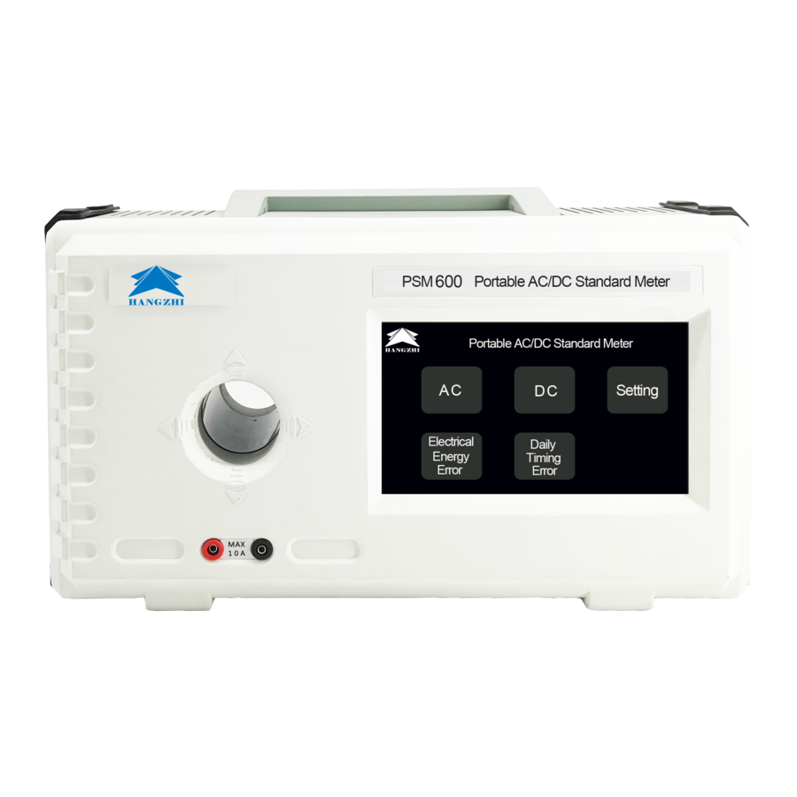
Page 14: Product Composition
2.3 Product composition Front Company logo Company logo The model and name of the Product model corresponding product Current measuring Perforation in the specified direction hole when measuring large current Terminals that are directly inserted during small current measurement, with Small current red terminal connected to current input, measuring terminal... - Page 15 Left DB9 interface Used for RS232, RS485, CAN communication USB interface Used for display program upgrade Aviation interface For pulse input and output Product serial number The unique serial number of the product Manufacturing nameplate For management purpose, please don’t peel off. Ground terminal Used to connect to the ground when using this instrument Right...
-
Page 16: Product Selection Guide And Technical Parameters
3 Product selection guide and technical parameters 3.1 Product selection PSM Series Product Selection PSM600-E PSM1000-E PSM1500-E DC Voltage Measurement (DCV) 20V~1000V 20V~1000V 20V~1000V DC Current Measurement (DCI) 500mA~600A 1A~1000A 75A~1500A AC Voltage Measurement (ACV) 30V~707V 30V~707V 30V~707V AC Current Measurement (ACI) -
Page 17: Phase And Frequency
PSM1500 Measuring Limit 1500A Measuring Range (0~110%)RG DC Current Accuracy ± 0.02%RD(75A≤I≤1500A) Resolution 0.002%RD(75A≤I≤1500A) Measuring Limit 1000V Measuring Range (0~110%)RG DC Voltage Accuracy ± 0.02%RD(20V≤U≤1000V) Resolution 0.002%RD(20V≤U≤1000V) Measuring Limit 1000A Measuring Range (0~110%)RG AC Current Accuracy ± 0.05%RD(50A≤I≤1000A) Resolution 0.005%RD(50A≤I≤1000A) Measuring Limit 707V Measuring Range... -
Page 18: Harmonic Measurement
3.4 Harmonic measurement Allowable error of harmonic measurement Grade To be measured Condition Allowable error Voltage Current Note: U denotes nominal voltage, U denotes harmonic voltage, I denotes rated current, I denotes harmonic current. 3.5 Other technical parameters Other technical parameters Power pulse output parameter (r/kwh) can be set from 1 to 2,000,000,000,and the maximum pulse frequency is 160kHz. -
Page 19: Instructions For Use
4 Instructions for use 4.1 Steps 1) Place the instrument 2) Check before measurement 3) Connect the power cord 4) Connect the test cable 5) Turn on the power 6) Start measuring 7) Record data 8) Measurement completed 4.2 Instructions of interface (For reference only, subject to delivery) 4.2.1 Boot interface The boot interface is displayed within 1-2 seconds after the power is turned on, and the boot interface is as shown below. -
Page 20: Ac Measurement Interface
4.2.3 AC measurement interface After clicking the “AC” button on the main interface, the AC measurement interface as shown below will appear. The AC interface can display voltage, current, frequency, phase, and active power. Click “Heavy current” or “10A” to select corresponding gear while “Heavy current” can be used in direct perforation measurement, "10A"... -
Page 21: Dc Measurement Interface
Click “Harmonic analysis” to enter harmonic analysis interface. 4.2.4 DC measurement interface After clicking the “DC” button on the main interface, the DC measurement interface as shown below will appear. The DC interface can display voltage, current and power. - Page 22 Click “Heavy current” or “10A” to select corresponding gear while “Heavy current” can be used in direct perforation measurement, "10A" can be used when accessing 10A small current. Click the "Word test" to enter the DC word test interface. Click the "Ripple measurement" to enter the ripple measurement interface.
-
Page 23: Setting Interface
4.2.5 Setting interface Click “Setting” to enter setting interface as shown below. In the setting interface, you can use calibration function and view information such as software version etc. 4.2.6 Power energy error Click “Power energy error” to enter power energy error interface. -
Page 24: Daily Timing Error Interface
Click “DC” to enter DC power energy error interface. 4.2.7 Daily timing error interface Click “Daily timing error interface” to enter daily timing error interface interface. -
Page 25: Connector Information
5 Connector information 5.1 DB9 terminal definition (DB9 male) Definition Description Connector picture RS485_B RS485 communication B RS232_RX RS232 transmission RS232_TX RS232 reception RS485_ A RS485 communication A RS485/RS232 isolated CAN_L CAN communication L CAN_G CAN communication isolation CAN_H CAN communication H Not connected 5.2 Aviation terminal definition Connection... -
Page 26: Dimensions
6 Dimensions Unit:mm, if not specified, the dimensional deviation is ±2mm or 1%, whichever is greater. -
Page 27: Maintenance And Service
7 Maintenance and service Warning Please do not modify, disassemble or repair the instrument. Failure to do so may result in fire, electric shock, or personal injury. 7.1 Calibration and repair •The calibration period varies depending on the customer's usage or environment. It is recommended to determine the calibration period based on the customer's usage or environment, and commission our company to make regular corrections. - Page 28 Possible reason → Action Item Please check Not powered Please confirm the continuity of the power cord The power is not Start Different power supply voltage and Not lit turned on (nothing is button frequency Please confirm the (extinguished) displayed) color rated power value (AC220±20%;...
-
Page 29: Attachment 1 Communication Agreement
Attachment 1 Communication agreement Please refer to “HZP communication agreement”. -
Page 30: Attachment 2 Psm600 Pulse Constant Comparison Table
Attachment 2 PSM600 pulse constant comparison table 600A DC energy pulse constant comparison table (automatic) 100V 200V 500V 1000V 0.2A 9.00×10 4.50×10 1.80×10 9.00×10 4.50×10 1.80×10 9.00×10 0.4A 4.50×10 2.25×10 9.00×10 4.50×10 2.25×10 9.00×10 4.50×10 1.80×10 9.00×10 3.60×10 1.80×10 9.00×10 3.60×10 1.80×10 Small current... - Page 31 424A AC energy pulse constant comparison table (automatic) 141V 354V 707V 0.13A 1.92×10 9.60×10 3.84×10 1.92×10 9.60×10 3.84×10 1.92×10 0.28A 9.00×10 4.50×10 1.80×10 9.00×10 4.50×10 1.80×10 9.00×10 0.7A 3.60×10 1.80×10 7.20×10 3.60×10 1.80×10 7.20×10 3.60×10 Small current 1.4A 1.80×10 9.50×10 3.60×10 1.80×10 9.50×10...
-
Page 32: Attachment 3 Psm1000 Pulse Constant Comparison Table
Attachment 3 PSM1000 pulse constant comparison table 1000A DC energy pulse constant comparison table (automatic) 100V 200V 500V 1000V 0.3A 6.00×10 3.00×10 1.20×10 6.00×10 3.00×10 1.20×10 6.00×10 0.6A 3.00×10 1.50×10 6.00×10 3.00×10 1.50×10 6.00×10 3.00×10 1.5A 1.20×10 6.00×10 2.40×10 1.20×10 6.00×10 2.40×10 1.20×10... - Page 33 707A AC energy pulse constant comparison table (automatic) 141V 354V 707V 0.2A 1.20×10 6.00×10 2.40×10 1.20×10 6.00×10 2.40×10 1.20×10 0.4A 6.00×10 3.00×10 1.20×10 6.00×10 3.00×10 1.20×10 6.00×10 2.40×10 1.20×10 4.80×10 2.40×10 1.20×10 4.80×10 2.40×10 Small 1.20×10 6.00×10 2.40×10 1.20×10 6.00×10 2.40×10 1.20×10 current...
-
Page 34: Attachment 4 Psm1500 Pulse Constant Comparison Table
Attachment 4 PSM1500 pulse constant comparison table 1500A DC energy pulse constant comparison table (automatic) 160V 320V 800V 1000V 100A 3.60×10 1.80×10 9.00×10 3.60×10 1.80×10 200A 1.80×10 9.00×10 4.50×10 1.80×10 9.00×10 400A 9.00×10 4.50×10 2.25×10 9.00×10 4.50×10 1000A 3.60×10 1.80×10 9.00×10 3.60×10 1.80×10...
Need help?
Do you have a question about the PSM Series and is the answer not in the manual?
Questions and answers