Table of Contents
Advertisement
Quick Links
Advertisement
Table of Contents

Summary of Contents for Pulsar BlackBox 130 UL
- Page 1 BlackBox 130 UL Instruction Manual...
- Page 3 Part Number M-130-0-004-1U COPYRIGHT © Pulsar Measurement, 2003 - 21. All rights reserved. No part of this publication may be reproduced, transmitted, transcribed, stored in a retrieval system, or translated into any language in any form without the written permission of Pulsar Process Measurement Limited.
-
Page 4: Table Of Contents
CONTENTS Chapter 1: Start Here… ......................7 About this Manual ....................... 7 About the BlackBox ......................8 Functional Description ....................... 9 Product Specification ....................... 10 EU Declaration of Conformity ..................12 Chapter 2 Installation ......................13 Unpacking ..........................13 Power Supply Requirements..................13 Safety Symbols ........................ - Page 5 PULSAR MEASUREMENT How to Access Program Mode ..................28 Directly Editing Parameters ................... 29 Test Mode ..........................30 Using the RS232 Serial Interface ................. 31 Parameter Defaults ......................32 Chapter 4 Programming Guide ..................33 Chapter 5 Parameter Guide ....................39 Menu System Diagrams ....................
- Page 6 BLACKBOX 130 UL INSTRUCTION MANUAL Breakpoints .......................... 68 Tables ............................. 69 Display Parameters ......................70 Options ..........................70 Failsafe ........................... 71 mA Output Parameters ....................72 Range ............................. 72 Operation ..........................72 Setpoint ..........................73 Limits ............................73 Trim ............................74 Failsafe ...........................
-
Page 7: Chapter 1: Start Here
There are various parts of the manual that offer additional help or information as shown. Tips TIP: Loo k for t his icon throughout your Pulsar Measurement manual to find helpful information and answers to frequently asked ques tions . -
Page 8: About The Blackbox
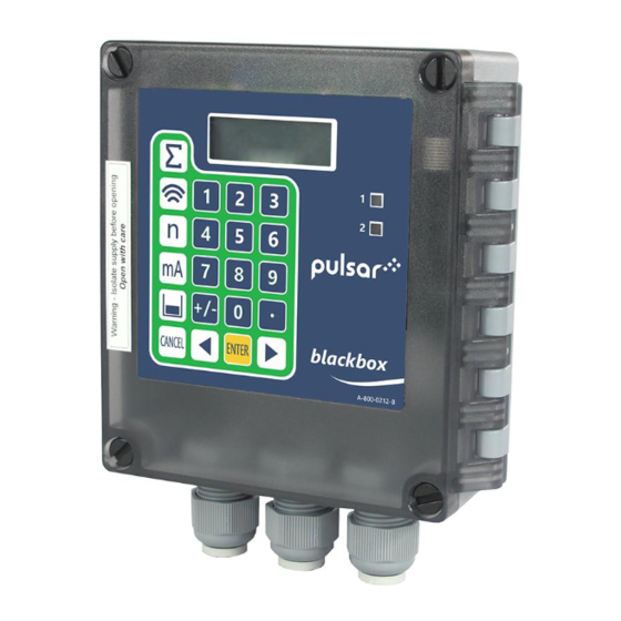
BLACKBOX 130 UL INSTRUCTION MANUAL About the BlackBox The Pulsar BlackBox is a non-contact Level Control System. It has been designed to provide a new concept in low-cost maintenance-free fit and forget level measurement without any compromise on performance. The BlackBox is ideally suited to applications where level monitoring, reporting, control, or logging is required, with or without the need for a local display. -
Page 9: Functional Description
The BlackBox utilises the unique DATEM software (Digital Adaptive Tracking of Echo Movement). This is a unique digital mapping technique developed especially for Pulsar’s range of ultrasonic level and control systems. It gives the system edge when identifying the “true target level” in the face of competing echoes from pipes, pumps, or other obstructions. -
Page 10: Product Specification
BLACKBOX 130 UL INSTRUCTION MANUAL Product Specification PHYSICAL Outside dimensions 5.63 x 5.91 x 2.5” (143 x 150 x 63.5 mm) Weight Nominal 1.54lbs (0.7 kg) ABS base with Polycarbonate lid, flammability rating Enclosure material/description UL94HB Underside fitted with 3 x M20, nylon cable glands Cable entry detail suitable for 6 –... - Page 11 Exm version of dB series transducers. REMOTE COMMUNICATOR Power supplied via BlackBox RS232 interface. Power Supply Pulsar Measurement operates a policy of constant development and improvement and reserve the right to amend technical details, as necessary.
-
Page 12: Eu Declaration Of Conformity
BLACKBOX 130 UL INSTRUCTION MANUAL EU Declaration of Conformity... -
Page 13: Chapter 2 Installation
If there is any shortage or obvious shipping damage to the equipment, report it immediately to Pulsar Measurement. Power Supply Requirements The BlackBox can operate from AC supply or from a DC battery and is... -
Page 14: Safety Symbols
BLACKBOX 130 UL INSTRUCTION MANUAL Safety Symbols Detailed below are descriptions and meanings of safety/warning symbols that are used on the FlowCERT and in this manual: SYMBOL DESCRIPTION DIRECT CURRENT (DC) ALETRNATING CURRENT (AC) PROTECTIVE CONDUCTOR TERMINAL CAUTION (Refer to accompanying Documents) -
Page 15: Dimensions
PULSAR MEASUREMENT When choosing a location to mount the enclosure, bear in mind the following: • Easy access to the enclosure is maintained. • The mounting surface is vibration-free. • The ambient temperature is between -20ºC and 50ºC (-4ºF and 120ºF). -
Page 16: Terminal Connection Detail
BLACKBOX 130 UL INSTRUCTION MANUAL The full dimensions of the enclosure are as shown below. 13mm 130mm (5.12”) 63.5mm (2.5”) (0.51”) 3 off M20 Glands Cable Entry There are 3 x M20 cable glands, suitable for 6 – 12mm cables, fitted to the base of the BlackBox enclosure. - Page 17 PULSAR MEASUREMENT Important Notice All cable glands should be tightened to the manufacturer’s specifications. The terminal compartment cover screws should be tightened to 0.5Nm Care should be taken not to over tighten the screws.
-
Page 18: Terminal Connections
BLACKBOX 130 UL INSTRUCTION MANUAL Terminal Connections Power The BlackBox can operate from mains AC and automatically from a DC power source or battery backup, in the event of power failure, or can be operated permanently from DC or batteries. -
Page 19: Atex
PULSAR MEASUREMENT ATEX For EEx m (Zone 1) applications a transducer certified to Sira 02ATEX5104X is used, and must be supplied via a 4000A breaking fuse, which is fitted as standard to the BlackBox level controller. For EEx ia (Zone 0) a transducer certified to Sira 02ATEX2103X is used, which must be connected to the BlackBox via an external Zener barrier. -
Page 20: Fuse Location
BLACKBOX 130 UL INSTRUCTION MANUAL Fuse Location The mains fuse is located, on the bottom board, to the left of the mains terminals, as illustrated below. Important Notice Before applying AC power (mains), make sure the supply is 115 VAC +5% / -10% Never operate the BlackBox with terminal access exposed. -
Page 21: Maintenance
There are no user serviceable parts inside your Blackbox, except the mains power fuse. If you experience any problems with the equipment, then please contact Pulsar Process Measurement for advice. Important Notice Please note that the on-board Lithium battery, mounted to the processor PCB, is not user serviceable. -
Page 22: Chapter 3 How To Use Your Blackbox
BLACKBOX 130 UL INSTRUCTION MANUAL CHAPTER 3 HOW TO USE YOUR BLACKBOX To view or change parameter values one of the following methods must be used: On board integral Keypad The onboard keypad can be used to program the BlackBox directly, or view parameters. -
Page 23: Handheld Communicator (Optional)
PULSAR MEASUREMENT Communication Port Configuration If the PC Handheld Programmer fails to connect to the BlackBox unit you may need to change the communications port that is being used, to do this ‘right click’ on the PC Handheld Programmer keypad and a ‘pop up’... -
Page 24: Operating The Controls
BLACKBOX 130 UL INSTRUCTION MANUAL measurement unit's chosen. Operating the Controls Display Whilst in the Run Mode it will display the current level or volume reading and its units of measurement, along with the mA output and status messages with regards to the communication status and Fail-Safe Mode. -
Page 25: Hot Keys
PULSAR MEASUREMENT Hot Keys There are five hot keys on the keypad, which can be used to quickly access common parameters for viewing only, while in Run Mode. Pressing the hot key once will display the first parameter, then repeated pressing will display the others, then the BlackBox reverts to Run Mode. -
Page 26: Menu Keys
BLACKBOX 130 UL INSTRUCTION MANUAL Menu Keys The menu keys have the following functions: Hot Key function 1) Arrow keys for moving left and right around the menu system. 2) Used in test mode to simulate the level moving up and down. -
Page 27: Run Mode
PULSAR MEASUREMENT There are two main operating modes for your BlackBox, Run Mode and Program Mode. There is also a Test Mode, used for checking the set-up. All modes are now described. Run Mode This mode is used once the BlackBox has been set up in program mode. It is also the default mode that the unit reverts to when it resumes operation after a power failure. -
Page 28: How To Access Program Mode
BLACKBOX 130 UL INSTRUCTION MANUAL How to Access Program Mode To enter program mode, you simply enter the passcode, via the keypad, followed by the ENTER key. The default passcode is 1997, so you would press the following: ENTER Important Notice There is a time-out period of 15 minutes when in program mode, after which time run mode will be resumed if you do not press any keys. -
Page 29: Directly Editing Parameters
PULSAR MEASUREMENT Once you have reached the relevant section, scroll through the parameters, and enter the necessary information. To enter the information, use the numeric keys and press ENTER and you will see the message “Saved!”. If you press CANCEL, then no change will be made, and the message “Unchanged!!”... -
Page 30: Test Mode
BLACKBOX 130 UL INSTRUCTION MANUAL Test Mode Test mode is used to simulate the application and confirm that all parameters and relay setpoints have been entered as expected. During simulation, there is a choice of whether the relays will physically change state (hard simulation) or not (soft simulation), the LED’s will always change... -
Page 31: Using The Rs232 Serial Interface
The RS232 serial interface is used to program the Blackbox, and communicate between the Blackbox and a PC using the optional BlackBox PC and other associated Pulsar software packages, to obtain information such as data logging and view echo traces upload, download and save parameter files. -
Page 32: Parameter Defaults
BLACKBOX 130 UL INSTRUCTION MANUAL Parameter Defaults Factory Defaults Important Notice When first installing the BlackBox, or subsequently moving or using the unit on a new application, before proceeding to program the unit for its intended application it is recommended that you ensure that all parameters are at their default values by completing a Factory Defaults P930, as described in Chapter 5 Parameter Guide. -
Page 33: Chapter 4 Programming Guide
PULSAR MEASUREMENT CHAPTER 4 PROGRAMMING GUIDE Example 1 Level Measurement Empty Distance (P105), 11.0 feet 100%. Span (P106), 10.0 feet (output = 20mA) High alarm on (P213), 8.5 feet High alarm off (P214), 8.0 feet Low alarm off (P224), 1.5 feet Low alarm on (P223), 1.0 feet... - Page 34 BLACKBOX 130 UL INSTRUCTION MANUAL To program the BlackBox for this Example, proceed as follows. Access the Program Mode, key in the passcode 1997 and press ENTER Using the menu system access the parameters, as detailed below, and select the relevant options and ENTER...
- Page 35 PULSAR MEASUREMENT Example 2 Alternating Control (Pump Down) A sump is typically used to temporarily hold water or effluent, and when the level reaches a specific point, the sump is pumped down, with the fluid being transferred to another process.
- Page 36 BLACKBOX 130 UL INSTRUCTION MANUAL To program the BlackBox for this Example, proceed as follows. Access the Program Mode, key in the passcode 1997 and press ENTER Using the menu system access the parameters, as detailed below, and select the relevant options and ENTER...
- Page 37 PULSAR MEASUREMENT Example 3 Volume A cylindrical tank with a diameter of 2m and a flat base that is typically used to temporarily hold liquid, and you wish to know the volume of liquid. You also require a high and low alarm.
- Page 38 BLACKBOX 130 UL INSTRUCTION MANUAL To program the BlackBox for this Example, proceed as follows. Access the Program Mode, key in the passcode 1997 and press ENTER Using the menu system access the parameters, as detailed below, and select the relevant options and ENTER...
-
Page 39: Chapter 5 Parameter Guide
PULSAR MEASUREMENT CHAPTER 5 PARAMETER GUIDE This chapter describes all the parameters in your BlackBox, in the order they appear in the menu system. Menu System Diagrams Shown below is a set of charts to show you how all the various parts can be found using the menu system. -
Page 40: Application Menu
BLACKBOX 130 UL INSTRUCTION MANUAL Application Menu SMS Time Operation Remote Alarm Distances P100 P104 P985 Tel. No 1 P995 Interval Mode Measurement Units P986 Tel. No 2 P996 SMS Start P101 P105 Transducer Empty Level P987 Tel. No 3... -
Page 41: Relays Menu
PULSAR MEASUREMENT Relays Menu Relay 1 Relay 2 P210 P220 R1 Type R2 Type P211 P221 R1 Function R2 Function P212 P222 R1 I/D R2 I/D P213 P223 R1 Setpoint R2 Setpoint P214 P224 R1 Setpoint R2 Setpoint P217 P227... -
Page 42: Data Logs Menu
BLACKBOX 130 UL INSTRUCTION MANUAL Data Logs Menu Temperature P580 Min Temp P581 Min Temp Date P582 Min Temp Time P583 Max Temp P584 Max Temp Date P585 Max Temp Time P586 Current Temperature... -
Page 43: Volume Menu
PULSAR MEASUREMENT Volume Menu Tables Conversion Breakpoints P600 P610 P696 Vessel Shape Reset Level Bkpt. 1 Bkpts. P611 P601 Vol. Bkpt. 1 As Required Vol. Dimension 1 P612, 614, 616, 618, P602 620, 622, 624, 626, As Required 628, 630, 632, 634, Vol. -
Page 44: Display Menu
BLACKBOX 130 UL INSTRUCTION MANUAL Display Menu Options Fail Safe P800 P808 Display Units Fail Mode P809 P801 Fail Time Decimal Places P802 Display Offset P804 Display Conversion mA Output Menu Range Operation Setpoints Limits Trim Fail Safe P830 P831... -
Page 45: Stability Menu
PULSAR MEASUREMENT Stability Menu Damping Filters P870 P881 Fill Damping Fixed Distance P871 P882 Empty Damping Process Filter... -
Page 46: Echo Processing Menu
BLACKBOX 130 UL INSTRUCTION MANUAL Echo Processing Menu Transducer (Xdr.) Status P900 Xdr. 1 Status P901 Echo Confidence P902 Echo Strength P903 Average Noise P904 Peak Noise P905 Sensitivity P906 Side Clearance... -
Page 47: System Menu
PULSAR MEASUREMENT System Menu Date System Daylight & Passcode Info Saving Time P926 P921 P970 P931 Software Enable DST Enable Date Revision Code P971 P932 P927 P922 Time Difference Hardware Passcode Revision P933 P972 Date DST Start P928 Format Time... -
Page 48: Test Menu
BLACKBOX 130 UL INSTRUCTION MANUAL Test Menu Simulation Hardware P980 P990 Simulate Self-Test P981 P991 Increment Hard Test P982 P992 Rate Out Test P993 Relay Test P994 Transducer Test... -
Page 49: Application Parameters
*9 = dBR16 Transducer is a mmWave radar. Range 0.252 to 52.49 feet *10 = dBR8 Transducer is a mmWave radar. Range 0.252 to 26.25 feet *Please consult Pulsar for versions of compatible firmware that the mmWAVE is available in. -
Page 50: Dimensions
BLACKBOX 130 UL INSTRUCTION MANUAL P102 Material This parameter should be set to the type of material being monitored OPTION DESCRIPTION 1 = Liquid Use for liquids and flat solids 2 = Solid Solid material that is heaped at an angle... - Page 51 PULSAR MEASUREMENT P106 Span This parameter should be set to the maximum distance from the Empty Level (P105) to the maximum material level. It is automatically set to be equal to the Empty Level (P105) less the Near Blanking distance (P107) when you set the empty level.
-
Page 52: Remote Alarm
Remote Alarm When a Modem is connected to the Blackbox, via the RS232 port, (Consult Pulsar or your local distributor for further details), the following parameters are used to set up the BlackBox so that when the level reaches a specific alarm point, as determined by the setting of the relay(s) the unit will dial and connect to a remote telephone number to provide details of the event. -
Page 53: Sms Time
This option initiates a connection to a remote modem/computer which will then allow remote 1 = Add 0 communication with the unit. Please consult Pulsar or your local distributor for further details. This option initiates a predetermined message which is sent to the remote telephone number detailing... - Page 54 BLACKBOX 130 UL INSTRUCTION MANUAL P998 SMS Days This parameter will determine on which days the SMS message is active and is entered as a Boolean value equating to the total of the days that the SMS message is required to be active.
-
Page 55: Relay Parameters
PULSAR MEASUREMENT Relay Parameters All relay related parameters are prefixed with a 2**. The second digit of the three-figure parameter number denotes the relay number as follows: 21* parameters for Relay 1 22* parameters for Relay 2 The third digit selects specific parameters for the setting up of the relays, which can be selected individually and results in the following parameter numbers for each relay. -
Page 56: Alarms
BLACKBOX 130 UL INSTRUCTION MANUAL Alarms P210, P220 =1 (Alarm) The second parameter for each relay determines the function of the alarm. P211, P221 - Relay Function This parameter defines what function the alarm will respond to as follows. OPTION... - Page 57 PULSAR MEASUREMENT P212, 222 - Relay Alarm ID When P211, P221 = 3 (Loss of Echo) or 4 (Loss of Clock). This parameter has no function and will not be displayed When P211, P221 = 1 or 2 This parameter defines which alarm type, the relay should respond to, as...
- Page 58 BLACKBOX 130 UL INSTRUCTION MANUAL The fourth parameter and the fifth parameter for each relay set the Alarm “ON” and “OFF” points. For a high alarm, the “ON” is set higher than “OFF”. For low alarm then “ON” is set lower than “OFF”. See the appropriate alarm ID, table (P212, 222) for further information.
-
Page 59: Control
PULSAR MEASUREMENT Control P210, P220 = 2 (Control) When a relay is being set up as a control relay, the second parameter that will be displayed in the menu determines its function. P211, P221 - Relay Function, This function is used, where it is required to energise the relay to switch a device, such as a pump, ON and de-energise the relay to switch the device OFF. - Page 60 BLACKBOX 130 UL INSTRUCTION MANUAL The third parameter determines if the control is fixed or alternating. P212, 222 Relay Control ID P210, 220 = 2 (Control) P211, 221 = 1 (General) OPTION DESCRIPTION 1 = Fixed All control devices are used to assist each other (run at the same time) and each device has its own setpoints.
-
Page 61: Common Parameters
PULSAR MEASUREMENT Common Parameters P217, P227 - Relay Closures This parameter displays the number of times the relay has activated since the relay has been in use. It can be reset with any value. P218, P228 - Relay Fail Safe The unit has a general fail-safe parameter P808. -
Page 62: Volume
BLACKBOX 130 UL INSTRUCTION MANUAL P584 Maximum Temperature Date This parameter displays the date when the maximum temperature was recorded. P585 Maximum Temperature Time This parameter displays the time when the maximum temperature was recorded. P586 Current Temperature This parameter displays the current temperature. - Page 63 PULSAR MEASUREMENT Conversion P600 Vessel Shape This parameter determines which vessel shape is used when utilising “Volume Conversion”. The choices are as shown in the table below, along with the dimensions that are required to be entered (P601-P603). P600 VALUE...
- Page 64 BLACKBOX 130 UL INSTRUCTION MANUAL VESSEL SHAPE P600 VALUE DESCRIPTION DIMENSIONS Cylinder diameter P600 = 4 Parabola Base and height of bottom P600 = 5 Flat Sloped Base Cylinder diameter Cylinder diameter P600 = Flat Sloped Base and height of...
- Page 65 PULSAR MEASUREMENT P600 = 10 Sphere Sphere diameter No dimensions required as level, P600 = 11 Universal linear and volume breakpoints are used No dimensions required as level, P600 =12 Universal curved and volume breakpoints are used...
- Page 66 BLACKBOX 130 UL INSTRUCTION MANUAL P601-P603 Vessel Dimensions These three parameters are used to enter the dimension required to calculate the volume. The dimensions required are as shown below and are entered Measurements Units (P104). VESSEL SHAPE P601 P602 P603...
- Page 67 PULSAR MEASUREMENT P605 Volume Units This parameter determines the units that you wish to display, for volume conversion. It is used in conjunction with P607 (maximum volume), and the units are shown on the display (subject to P810). The choices are:...
-
Page 68: Breakpoints
BLACKBOX 130 UL INSTRUCTION MANUAL Breakpoints P610-P673 Level/Volume Breakpoints These parameters are used to create a profile of the vessel when P600=11 (universal linear) or P600=12 (universal curved). You should enter breakpoints in pairs, a reading for level and its corresponding volume. The more pairs you enter, the more accurate the profile will be. -
Page 69: Tables
PULSAR MEASUREMENT Universal Curved (P600=12) This volume calculation creates a curved approximation of the level/volume relationship, and works best if the vessel is non-linear, and there are no sharp angles. Level You should enter 2 level/volume breakpoints at the minimum and maximum levels, and several for each place where the vessel has got an arc. -
Page 70: Display Parameters
BLACKBOX 130 UL INSTRUCTION MANUAL Display Parameters Options P800 Display Units This parameter determines whether the reading displayed is in Measurement Units (P104), or as a percentage of span. OPTION DESCRIPTION 1 = Measured (Default) Display is in selected unit’s dependant on... -
Page 71: Failsafe
PULSAR MEASUREMENT P804 Display Conversion The reading is multiplied by the value of the parameter before being displayed. The default is 1.0, and will be applied when P802 Display Offset is set to a different value other than its default value of ‘0’. -
Page 72: Ma Output Parameters
BLACKBOX 130 UL INSTRUCTION MANUAL mA Output Parameters Range P830 Output Range This parameter determines the range of the mA output, from the following. OPTION DESCRIPTION 0 = Off Output disabled Output directly proportional to the output mode 1 = 0 to 20mA (P831), so if the reading is 0% the output is 0 mA. -
Page 73: Setpoint
PULSAR MEASUREMENT Setpoint By default, the mA output will represent the empty (0 or 4mA dependant on (P830) Out Range) and 100% of the operational span (20mA), but you may wish to have the output represent a section of the operational span. For... -
Page 74: Trim
BLACKBOX 130 UL INSTRUCTION MANUAL Trim P838 Output Low Trim If the device you are connected to is not calibrated, and not showing the correct low value (reading), then you can trim it using this parameter. You can either type in the offset directly or use the arrow keys to move the output up and down until you get the expected result (reading) on the device that is connected. -
Page 75: Compensation Parameters
PULSAR MEASUREMENT Compensation Parameters Offset P851 Measurement Offset The value of this parameter is added to the measured distance, in Measurement Units (P104). This Offset will be added to the level, as derived from the transducer, and will affect everything including the reading on any display in use, relay setpoints and the output. -
Page 76: Stability Parameters
BLACKBOX 130 UL INSTRUCTION MANUAL Stability Parameters Damping Damping is used to damp the display, to enable it to keep up with the process but ignore minor surface fluctuations. P870 Fill Damping This parameter determines the maximum rate at which the unit will respond to an increase in level. -
Page 77: Echo Processing Parameters
PULSAR MEASUREMENT Echo Processing Parameters Transducer Status P900 Transducer Status This parameter shows the current state of the transducer. The value means the following. OPTION DESCRIPTION 0= OK (Default) Transducer working correctly. 1= Disabled Transducer is not being used 2= Stuck High... -
Page 78: System Parameters
BLACKBOX 130 UL INSTRUCTION MANUAL P905 Sensitivity This parameter determines the sensitivity of the unit. Please consult Pulsar for further information and assistance on changing the value of this parameter. P906 Side Clearance This parameter is used to set the distance by which the DATEM trace will “stand-off”... -
Page 79: Date & Time
PULSAR MEASUREMENT P930 Factory Defaults This parameter resets all parameter values to the original Factory Set values that were installed when the unit was tested before despatch to you. To reset parameters, enter 1 (Yes), and press ENTER, then you will see a message “Entr if sure”, you should press ENTER again. - Page 80 BLACKBOX 130 UL INSTRUCTION MANUAL Default = 01:00 P972 DST Start Time This parameter is used to set the time of day at which Daylight Saving Time will start, the time is entered in the format HH: MM (24-hour format).
- Page 81 PULSAR MEASUREMENT P975 Start Month This parameter is used to select the month in which Daylight-Saving Time is to start. OPTION DESCRIPTION 1 = January DST will start during the month of January 2 = February DST will start during the month of February...
- Page 82 BLACKBOX 130 UL INSTRUCTION MANUAL P978 End Week This parameter will determine the week of the month (P975) in which Daylight-Saving Time is to end. OPTION DESCRIPTION 1 = Week 1 DST will end on day (P973) in the first week (P974) of the month (P975).
-
Page 83: Test Parameters
PULSAR MEASUREMENT Test Parameters Simulation P980 Simulate Test mode is used to simulate the application and confirm that all parameters and relay setpoints have been entered as expected. During simulation, there is a choice of whether the relays will change state (hard simulation) or not (soft simulation), but the LED’s will always switch... -
Page 84: Hardware
BLACKBOX 130 UL INSTRUCTION MANUAL P983 Test Max This parameter determines the maximum of the simulated measurement values. Default = 1000 P984 Test Min This parameter determines the minimum of the simulated measurement values. Default = 0 Hardware P990 Self Test If you enter 1 for this parameter, then the unit will perform a self-test. - Page 85 PULSAR MEASUREMENT P993 Relay Test Press a numeric key corresponding to the number of the relay you wish to test, and the relay will change state each time the key is pressed. If you press any other key, other than a valid relay number, then the test will end.
-
Page 86: Chapter 6 Troubleshooting
BLACKBOX 130 UL INSTRUCTION MANUAL CHAPTER 6 TROUBLESHOOTING This section describes many common symptoms, with suggestions as to what to do. If the issue persists, please contact your local Pulsar distributor. SYMPTOM WHAT TO DO No reading being obtained, Check power supply. Check wiring to transducer not firing. -
Page 87: Chapter 7 Disposal
PULSAR MEASUREMENT CHAPTER 7 DISPOSAL Incorrect disposal can cause adverse effects to the environment. Dispose of the device components and packaging material in accordance with regional environmental regulations including regulations for electrical \ electronic products. Transducers Remove power, disconnect the Transducer, cut off the electrical cable and dispose of cable and Transducer in accordance with regional environmental regulations for electrical \ electronic products. - Page 88 BLACKBOX 130 UL INSTRUCTION MANUAL www.pulsarmeasurement.com S U P P O R T @ P U L S A R M E A S U R E M E N T . C O M Copyright © 2020 Pulsar Measurement Ltd.
Need help?
Do you have a question about the BlackBox 130 UL and is the answer not in the manual?
Questions and answers