Advertisement
Quick Links
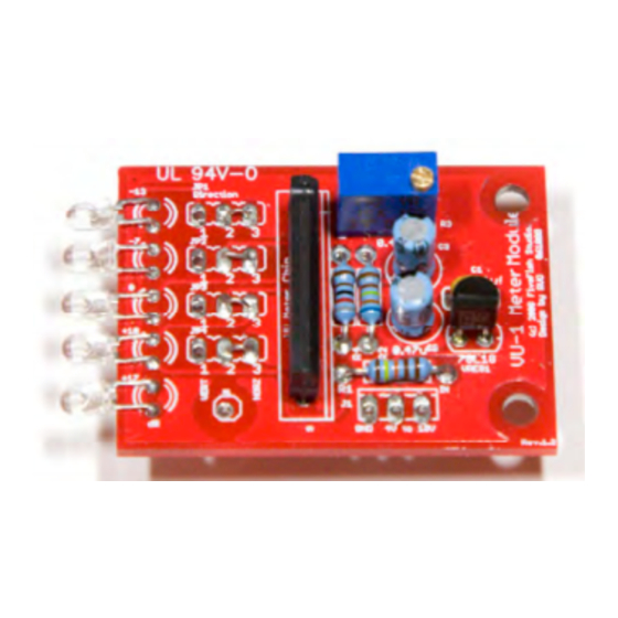
VU-1MK500 VU Meter Kit
Volume Unit Meter
Simplicity Counts, Detail Matters.
No part of this document may be reproduced, either mechanically or electronically, posted online on the
Internet, in whole or in part, without the expressed, written permission of FiveFish Studios. This document is
solely provided to the kit builder of the VU-1MK500 VU Meter Kit.
Last Revision: September 18, 2011
Copyright © 2011 FiveFish Studios
www.fivefishstudios.com
Advertisement

Subscribe to Our Youtube Channel
Summary of Contents for FiveFish Studios VU-1MK500
- Page 1 No part of this document may be reproduced, either mechanically or electronically, posted online on the Internet, in whole or in part, without the expressed, written permission of FiveFish Studios. This document is solely provided to the kit builder of the VU-1MK500 VU Meter Kit.
- Page 2 VU-1mk500 VU Meter Kit Congratulations and thank you for your purchase of the VU-1MK500 VU Meter Kit. Countless hours has been spent in the design, manufacturing and packaging of this kit to deliver to you a Volume Unit Meter (VU Meter) Kit at a very affordable price! There are no special, expensive tools or techniques required to assemble this kit.
- Page 3 Mini Pliers Cutter – to cut component leads, wires, strip insulation off wires (if you don’t have a wire- stripper tool). Mini Long Nose Pliers – to bend component leads, use as a heatsink, hold components, tighten bolts. Manual Solder sucker pump – sucks up solder when you made a mistake soldering components on the PCB.
- Page 4 VU-1MK500 VU Meter Parts Identification and Assembly Notes For the newbies, this is not meant to be a full tutorial about electronics. But I want you to be able to identify components, recognize them and know what their basic functionality is.
-
Page 5: Electrolytic Capacitors
Capacitance values may be expressed in microfarads (uf), nanofarad (nf) or picofarads (pf). The conversion between these units are shown on the table above. Electrolytic Capacitors Electrolytic capacitors are cylindrical in construction. Unlike ceramic capacitors, electrolytic capacitors USUALLY/MOSTLY have polarity. One side is marked with the (-) sign, also called the cathode, or negative side. Just like ceramic capacitors, they are also measured in microfarads (uf) and have a maximum voltage rating. - Page 6 Trimmer The VU Meter Kit features a 25-turn trimmer potentiometer. This is used for calibrating your VU Meter. (More on this later.) LED – Light Emitting Diodes LEDs are a special kind of diode that lights up when current goes through it. We’re using low-current, high efficiency LEDs for the VU Meter Kit.
-
Page 7: Left Right
Jumpers The VU Meter Kit can be installed either horizontally or vertically. Normally, VU Meter movement go from LEFT RIGHT or BOTTOM TOP direction. That means, when the VU Meter Kit board is installed in a vertical configuration, you want your LED movement going from BOTTOM ... - Page 8 Also, the IC chip has very fine pin spacing. You need good eyesight to solder all pins properly without shorting them together. VU-1MK500 Assembly Guide The general guideline in electronics assembly is to solder the smallest/shortest component first (resistors), and solder the bigger/taller components last (ceramic capacitors, electrolytic capacitors, headers, etc).
- Page 9 STEP 2. Solder all 1/4-watt resistors and inductors to the PCB. The orientation does not matter. Build Notes: There are some discrepancies between the silkscreen on the PCB and parts list. PCB value 6K32 = 6K34 on parts bag PCB value 8K = 8K2 on parts bag STEP 3.
- Page 10 STEP 6: Solder the IC Chip. Note orientation of pin #1. The V-notch of the chip should be on the left side. Solder one pin first, check orientation and alignment, then solder the rest of the pins. If crooked, reheat the first leg and straighten the chip before soldering the rest of the pins.
- Page 11 STEP 9: Solder a 1.0” to 1.25” length of wire on the solder pad connections of the PCB. VU-1MK500 Installation Guide The VU meter only needs (3) wires to get it working. Look at header J1. 1. The first pin is labeled “IN”. This is connected to either pin2 or pin3 of the XLR output jack.
- Page 12 Check that you have signal coming out of your preamp/XLR jack. Make sure it is strong enough to register on the VU Meter Kit. VU-1MK500 PCB Component Layout Guide VU-1MK500 VU Meter Bill of Materials Part Desc Custom PCB VREG1...
- Page 13 No part of this document may be reproduced, either mechanically or electronically, posted online on the Internet, in whole or in part, without the expressed, written permission of FiveFish Studios. This document is solely provided to the kit builder of the VU-1MK500 VU Meter Kit.
Need help?
Do you have a question about the VU-1MK500 and is the answer not in the manual?
Questions and answers