Table of Contents
Advertisement
Quick Links
OPERATING INSTRUCTIONS
NOTE
In case of doubt, the original German version
of the operating instructions applies.
TorqBee
- Original operating instructions -
®
Battery tightening tool
TBPxx-xxx / TBAxx-xxx / TBSxx-xxx
Issue date:
Tool Firmware:
HST-Tool-Manager:
February 2021
from 2.2.6.0
from 2.0.6.0
Advertisement
Table of Contents

Related Manuals for HS-Technik TorqBee TBP Series


Summary of Contents for HS-Technik TorqBee TBP Series
- Page 1 OPERATING INSTRUCTIONS TorqBee ® - Original operating instructions - Battery tightening tool TBPxx-xxx / TBAxx-xxx / TBSxx-xxx NOTE Issue date: February 2021 In case of doubt, the original German version Tool Firmware: from 2.2.6.0 of the operating instructions applies. HST-Tool-Manager: from 2.0.6.0...
-
Page 2: Table Of Contents
Table of contents 1 Operating principles Scope of delivery General information Signs and symbols used Structure of the warnings Technical terms and abbreviations used Intended use Improper use Duties of the operator Duties of personnel 1.10 Training of personnel 1.11 Guarantee and liability 1.12 Copyright... - Page 3 5 Display Display indicators HST-Tool-Manager 5.2.1 Setup 5.2.2 General → Process control 5.2.3 General → Energy & Lighting 5.2.4 General → Features 5.2.5 General → TM version 5.2.6 Management 5.2.7 Signals → OLED-display 5.2.8 Signals → LED 5.2.9 Signals → Sound signals 5.2.10 Signals →...
-
Page 4: Operating Principles
1 Operating principles Dear customers, thank you for choosing a HS-Technik GmbH product. This quality product „Made in Germany“ fulfils the highest requirements with regard to performance, quality and accuracy. When used correctly the product will undoubtedly perform very well for many years. -
Page 5: Signs And Symbols Used
This operating instructions must be read and applied by every person who is assigned to conduct work using this tool. In addition to these operation instructions the applicable regulations on accident prevention and environmental protection should be observed. NOTE After reading, keep the operating instructions in a place accessible to every operator. -
Page 6: Structure Of The Warnings
Structure of the warnings The warnings are structured as follows: DANGER Indicates an immediate dangerous situation that can lead to serious or even deadly injuries and/or that could seriously damage or even destroy the tool. WARNING Indicates a potentially dangerous situation that can lead to serious injuries and/or damage to the tool. -
Page 7: Intended Use
• following all indications of the operating instructions and • observance of inspection and maintenance works. Any other use or use beyond that is considered improper use. HS-Technik GmbH is not liable for any damage resulting from this. - 7 -... -
Page 8: Improper Use
Improper use DANGER The use of this tool for other purposes, e.g. for hammering, is not permitted. Improper use or incorrect accessories can lead to dangers with unforeseeable consequences. We accept no liability for damage and malfunctions resulting from non-observance of these operating instructions and improper use. -
Page 9: Training Of Personnel
1.10 Training of personnel Only trained and instructed personnel should work with this tool. The responsibilities of the personnel must be clearly defined. Trainees may only work with this power tool under the supervision of an experienced person. 1.11 Guarantee and liability Guarantee and liability claims for personal injury and property damage are excluded, if caused by one or more of the following: •... -
Page 10: Copyright
These operating instructions are intended solely for the operator and its personnel. They contain guidelines and information which may not be fully, or partially • reproduced • distributed or • otherwise shared. The copyright of these operating instructions is retained by HS-Technik GmbH. Manufacturer’s address: Im Martelacker 12 D-79588 Efringen-Kirchen Telephone:... -
Page 11: General Safety Information For Power Tools
2 General safety information for power tools DANGER Read all the safety information, instructions, illustrations and technical data which is provided with this power tool. Failure to follow the instructions below may result in electric shock, fire and/or serious injury. WARNING This power tool was manufactured in according with current state-of-the-art technology and recognised technological safety guidelines. -
Page 12: Electrical Safety
Electrical safety a) Avoid body contact with grounded surfaces such as pipes, heaters, stoves and refrig- erators. There is an increased risk of electric shock if your body is grounded. b) Keep power tools away from rain or moisture. Penetration of water into a power tool increases the risk of electric shock. -
Page 13: Use And Handling Of Power Tools
e) Wear suitable clothing. Do not wear loose clothing or jewellery. Keep hair and cloth- ing away from moving parts. Loose clothing, jewellery or long hair can get caught in moving parts. f) Do not lull yourself into a false sense of security and do not disregard the safety rules for power tools, even if you are familiar with the power tool after repeated use. -
Page 14: Use And Handling Of Battery Tools
h) Keep handles and gripping surfaces dry, clean and free of oil and grease. Slippery han- dles and gripping surfaces do not allow safe operation and control of the power tool in unforeseen situations. i) Use the correct power tool. Do not use under-performing tools for heavy loads. Do not use tools for purposes and work for which they are not intended. -
Page 15: Service
g) Follow all instructions for charging and never charge the battery or the battery tool outside of the temperature range specified in the operating instructions. Incorrect charging or charging outside of the approved temperature range can damage the bat- tery and increase the risk of fire. Service a) Only have your power tool repaired by qualified professional staff and only with orig- inal replacement parts which can be available at HS Technik GmbH. -
Page 16: Important Information About This Tool
3 Important information about this tool Handling the associated lithium ion battery a) Observe the operation instructions of the Li-Ion battery. b) If the battery will not be used over a longer period of time it may not remain on the charger or on the machine. -
Page 17: Information On The Associated Charger
No changes, additions or conversions to the power tool may be made without the approval of the manufacturer. All conversion measures require written permission and confirmation by HS-Technik GmbH. WARNING In the event of the replacement of wear and tear parts only original replacement parts may be used. -
Page 18: Cleaning The Device And Disposal
Cleaning the device and disposal Substances and materials used must be handled and disposed of properly, particularly when cleaning with solvents. Do not throw the used battery into the household waste, fire or water, instead have it professional disposed of by a specialist or the manufacturer. - 18 -... -
Page 19: Start-Up And Use
4 Start-up and use DANGER Risk of injury from damaged tools Damaged tools can lead to injuries or damages. • All damaged parts must be repaired before use. Risk of injury from falling tools Falling tools can lead to injuries or damages. •... -
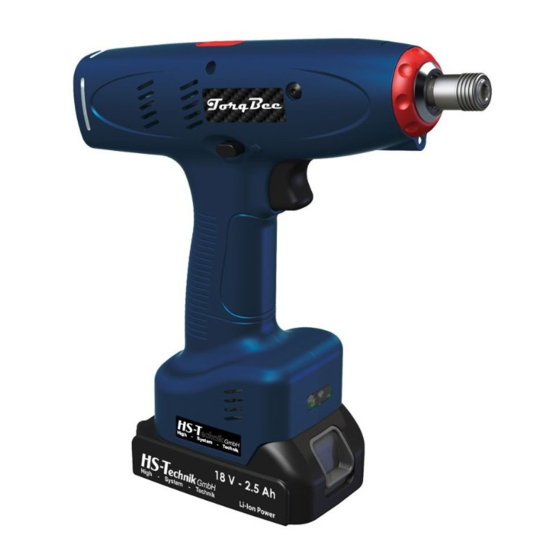
Page 20: Tool Structure
Tool structure 10. LED for work area lighting 1. OLED Display* 11. Optional Wi-Fi* 2. Multi-colour LED 12. Optional barcode scanner* 3. Brushless motor 13. 18 V Li-ion battery 4. Colour coding 14. 1/4”-hexagon socket tool holder 5. Clutch entry** 15. - Page 21 - 21 -...
- Page 22 - 22 -...
- Page 23 NOTE Depending on the tool configuration various functions, which are described in the operating instructions, may be used. In addition these basic functions are associated with several sub-functions. Included in the scope of delivery Optional Shut-off Torque Reaction OLED Barcode Article Wi-Fi clutch...
-
Page 24: Operation
Operation 4.2.1 Inserting and removing the battery • In order to insert the battery (1), align it so that it can be easily pushed onto the mount- ing provided along the plastic guide. After sliding it on completely, the fastening clip (2) must lock the battery firmly and properly into place in the tool housing. -
Page 25: Press Start Button
4.2.2 Press start button Pressing or releasing the start button starts or stops the tool. NOTE The tool only starts up when the battery has sufficient capacity. * – Start button 4.2.3 Clockwise / Counterclockwise rotation switch WARNING Risk of injury as a result of accidental actuation of the start button When pulling the battery off the start button can accidentally be actuated. -
Page 26: Led / Barcode Scanner
4.2.4 LED / Barcode scanner WARNING Risk of injury from the light emitting diode Looking directly into the light emitting diode can lead to eye injuries. • Never look directly into the light emitting diode. After pressing the start button, the LED and the barcode scanner switch on. The afterglow time of the LED can be defined in the HST-Tool-Manager under Settings - General after actuating the start button. -
Page 27: Setting The Tightening Torque At Pistol Tools
4.2.6 Setting the tightening torque at pistol tools With the TorqBee® Light / TorqBee® SO / TorqBee® SOP series, the tightening torque is set using a mechanical shut-off clutch. • To adjust the clutch, the protective clip must first be removed from the clutch. •... -
Page 28: Setting The Tightening Torque At Angle & Straight Tools
In the TorqBee® ECO, EC and EC² series the tool is programmed using the HST-Tool- Manager Software. Make sure that the tool is properly configured and parametrised. NOTE See HST-Tool-Manager operating instructions. 4.2.7 Setting the tightening torque at angle & straight tools With the TorqBee®... -
Page 29: Cancel Order
4.2.8 Cancel order If you want to execute an order later or if you scanned an incorrect barcode you can cancel it after it was enabled. To do this press and hold the menu button (middle display button) for approx. 3 seconds. The cancel symbol will appear. Confirm this with the left display button. - Page 30 The following points are available in the set-up menu: The current battery voltage, RSSI network coverage, and the firmware version can be displayed under menu item „Info“. The scanner can be selected under the scanner menu item in order to read in the network settings using a barcode. Scanning for program selection is not possible in this mode.
- Page 31 If the connection to the sequence control (radio connection via access point) is cancelled and a work order was already approved in the tool this should continue to be executed if possible. Even after completion of the work order the tool will attempt to send the tool results.
-
Page 32: Operation
(cam-out effect). In order to ensure the safety and reliability of the product repairs, any other possible main- tenance or adjustments should be completed by HS-Technik GmbH or an authorised spe- cialised company. -
Page 33: Display
5 Display Display indicators The display indicators can be adjusted in the HST-Tool-Manager so that, for example, precise values for the fittings, the angle of rotation, only one OK or NOK, or the count process can be displayed for the worker. The display indications can be shown in German and English. - Page 34 Display notification Meaning Battery state of charge: 50 % - 100 % 19320012 READY Battery state of charge: 30 % - 50 % 19320012 READY Battery state of charge: 10 % - 30 % 19320012 READY Battery state of charge: 5 % - 10 % 19320012 READY Battery state of charge: less than 5 % 19320012 BATT EMPTY The device is ready for use.
- Page 35 Display notification Meaning Product ID must be scanned before the tool will be enabled. Symbol may 19320012 also be a car. SCAN BARCODE Tool is locked and is being configured using the HST-Tool-Manager via Wi-Fi. Battery may not be removed. The targets could not be reached for the tightening process.
- Page 36 Display notification Meaning Previously lost connection to the network was restored. 19320012 reconnect OK Releasing the start button during the tightening process is permitted. 000/001 NO NUMBER Start button was released during the tightening process. It can be contin- ued to tighten. When using the barcode scanner the corresponding bar- code will be displayed in the blue display indicator.
- Page 37 Display notification Meaning Worker must examine the screw himself after a tightening process and 000/001 then personally acknowledge it afterwards with time input (e.g. 15 sec- onds) on the display. The timer runs backwards for orientation. (Image is at 10.9 seconds) If he does not acknowledge the screw within the time it NOK 10.9 is automatically valued as NOK.
- Page 38 Display notification Meaning Motor overheating → Contact the manufacturer STOP TEMP MOT Maximum logic voltage exceeded, tool must be repaired! STOP FAIL VCC MAX SD-card in tool not available or defective. If the problem cannot be re- solved with a new SD card, please contact the manufacturer. STOP NO SD CARD Tool cannot connect to the network.
-
Page 39: Hst-Tool-Manager
If an update of your tool is necessary the HST- Tool-Manager will inform you. 1. Start the HST-Tool-Manager by double clicking the HST-Tool-Manager icon: 2. Log-in with the required User, a list of the passwords can be requested from HS-Technik (support@hs-technik.com). - 39 -... - Page 40 3. Insert the USB cable included into the Mini-USB socket at the bottom of the tool and the opposite end into an open USB interface on your laptop / tablet / PC. 4. Click on the „read“ button on the top right. - 40 -...
- Page 41 5. The HST-Tool-Manager will now read the settings from your tool and will display its pro- gress using a green bar. At the end the tool overview will be displayed. - 41 -...
-
Page 42: Setup
5.2.1 Setup Clicking on setup takes you to the tool settings menu. Here, for example, the display, LED display or the energy savings settings can be parameterised. 5.2.2 General → Process control - 42 -... - Page 43 „Manual mode active“ If the check box is activated the tool will operate in manual mode. I.e. the standard program (yellow start) will always be conducted. In this mode the counting function, Wi-Fi and barcode are deactivated. „enable over“ The drop-down menu is used to select how the tool will be approved. In order to use this function manual mode must be deactivated.
-
Page 44: General → Energy & Lighting
5.2.3 General → Energy & Lighting Here you can parametrise the energy savings options and the LED work lighting. „Energy saving“ The energy saving options can be activated or deactivated with the check-box. „Display shut off after“ Time in seconds without action after which the OLED display of the tool will switch off and the screen saver is activated. -
Page 45: General → Features
5.2.4 General → Features „Setup menu“ Activates and deactivates the setup menu using the display buttons. If this function is activated you can enter the setup menu by holding down the yellow menu button on the display. „Scanner selectable“ If this function is activated you can activate and deactivate the barcode scanner using the setup menu on the tool. -
Page 46: General → Tm Version
5.2.5 General → TM version The TM version tab will display the HST-Tool-Manager version required for this tool, at minimum, the version intended for the application, and the version last written with on the tool. - 46 -... -
Page 47: Management
5.2.6 Management The data on the operating site and the inventory number of the tool can be saved under administration. location max. 20 characters inventory number max. 40 characters - 47 -... -
Page 48: Signals → Oled-Display
5.2.7 Signals → OLED-display „Language“ Select the language on the OLED display, German or English Default: English „display of results“ Select the result presentation on the OLED display. „Units“ Selection of the physical unit for the torque. „enable display“ Selection for what is to be displayed on the tool display when the tool is enabled. -
Page 49: Signals → Led
5.2.8 Signals → LED The LEDs around the OLED display can be parametrised under the LED tab. The colour of the LEDs can be changed by clicking on the coloured square. „Duration“ The duration of the display in seconds, max. 25.5 seconds. „Period“... -
Page 50: Signals → Sound Signals
5.2.9 Signals → Sound signals „Duration“ For the duration the time of the acoustic signal for OK and NOK results will be parametrised in seconds, max. value 3.0 seconds. „at start“ When the check-box is selected a signal will sound when the tool starts. „during scan“... -
Page 51: Signals → Vibration Alarm
5.2.10 Signals → Vibration alarm „Duration“ For the duration the time of the vibration for OK and NOK results will be parametrised in seconds. - 51 -... -
Page 52: Graphics
5.2.11 Graphics „Measured“ Selection of the physical parameters of the curve display depending on the tool type. - Torque, angle, current, voltage - Torque, angle, current - Torque, angle - Torque Torque 1, torque 2, MDM/MDP Torque 1, torque 2, angle 1, angle 2 „Sampling rate“... -
Page 53: System Time
5.2.12 System time In the system time tab the real time clock (RTC) can be synchronised with the time of the computer connected. The real time clock is still supplied with power internally via a capacitor even if the battery is disconnected from the tool. -
Page 54: Basic Settings
5.2.13 Basic settings Under „basic settings“ accessories can be activated, such as Wi-Fi and barcode scanner as well as the recovery function. Wi-Fi and scanner are automatically activated if these functions are selected under „General → Process control → Approval via“. „Display“... -
Page 55: Update
5.2.14 Update Select Click on select and find the .upd file provided by HS-Technik GmbH. Please select automatic under „Recovery mode“. Then click „start“. The progress of the update will be displayed using a status bar and confirmed at the end with „done“. -
Page 56: Programs
A detailed guide on this can be found in the operating instructions of our HST-Tool-Manager (download at www.hs-technik.com/software) NOTE We recommend using the support of the HS-Technik service personnel during initial start-up in order to determine the perfect parameters for your application. -
Page 57: Accessories
An exploded view and a replacement parts list can be requested from us with specification of the Item no. at info@hs-technik.com or by telephone at +49 (0) 7628 / 9111-0. NOTE All tools will be delivered with software. -
Page 58: Storage
7 Storage Observe the following information when storing tools, batteries and chargers: • Remove the battery when you are not using the tool. • If you will not be using the battery for a longer period of time it should be stored, fully charged, in a dry, dust-proof area. -
Page 59: Technical Data
8 Technical data Technical data for all tool types Description TBXXX-Y Operating voltage 18 VDC Noise emissions (L < 72 dB(A) Measurement uncertainty (K 2.5 dB(A) Vibration (a < 2.5 m/s² Measurement uncertainty (K 0.1 m/s² Operating altitude < 2000 mNN Operating temperature 10 - 40 °C Storage temperature... -
Page 60: Pistol Tool
Pistol tool TorqBee Light Torque Max. speed Tool adapter Dimensions L × W × H Weight TBPL-4 1.0 - 4.0 Nm 1,400 rpm 1/4" - Form E 230 × 72 × 211 mm 1.20 kg TBPL-6 1.5 - 6.5 Nm 1,100 rpm 1/4"... - Page 61 hexagon DIN 3126-F6,3 Innensechskant DIN 3126-F6,3 TBPx Specifications in mm Not shown to scale - 61 -...
-
Page 62: Angle Tool
Angle tool TorqBee Light Torque Max. speed Tool adapter Dimensions L × W × H Weight TBAL-10-2 1.5 - 9.0 Nm 750 rpm 1/4” square 440 × 72 × 94 mm 1.50 kg TBAL-12-3 2.5 - 12.0 Nm 550 rpm 3/8”... - Page 63 TorqBee ECO Torque Max. speed Tool adapter Dimensions L × W × H Weight TBAECO-12*-3 5.0 - 12.0 Nm 550 rpm 3/8” square 455 × 72 × 94 mm 1.51 kg TBAECO-20*-3 5.0 - 20.0 Nm 400 rpm 3/8” square 455 ×...
- Page 64 TorqBee Light/SO/SOP/ECO/EC TBAL-10-2 TBASO-10-2 square DIN 3121-E6,3 TBASOP-10-2 Außenvierkant DIN 3121-E6,3 Außenvierkant DIN 3121-E6,3 TBAEC2-10-2 TBAx-10-2 TBAx-10-2 TBAL-12-3 TBAL-20-3 TBASO-12-3 TBASO-20-3 TBASOP-12-3 TBASOP-20-3 TBAECO-12-3 TBAECO-20-3 square DIN 3121-E10 Außenvierkant DIN 3121-E10 TBAEC2-12-3 TBAEC2-20-3 TBAx-12/20-3 TBAL-30-3 TBASO-30-3 TBASOP-30-3 square DIN 3121-E10 TBAECO-30-3 Außenvierkant DIN 3121-E10 Außenvierkant DIN 3121-E10...
- Page 65 TorqBee Light/SO/SOP/ECO/EC TBAL-55-3 TBASO-55-3 TBASOP-55-3 square DIN 3121-E10 Außenvierkant DIN 3121-E10 TBAECO-55-3 Außenvierkant DIN 3121-E10 TBAEC2-55-3 TBAx-55-3 TBAx-55-3 TBAL-85-5 TBASO-85-5 square DIN 3121-E12,5 Außenvierkant DIN 3121-E12,5 TBASOP-85-5 Außenvierkant DIN 3121-E12,5 TBAECO-85-5 TBAEC2-85-5 TBAx-85-5 TBAx-85-5 Specifications in mm Not shown to scale - 65 -...
- Page 66 TorqBee EC TBAEC-10 TBAEC2-10 hexagon DIN 3126-F6,3 Innensechskant DIN 3126-F6,3 TBAEC-20 TB-A-L-SO-SOP-10 TBAEC2-20 square DIN 3121-E10 Außenvierkant DIN 3121-E10 Specifications in mm Not shown to scale TB-A- - 66 -...
- Page 67 TorqBee EC TBAEC-30 TBAEC2-30 square DIN 3121-E10 Außenvierkant DIN 3121-E10 TB-A-EC-30 TBAEC-55 TBAEC2-55 square DIN 3121-E12,5 Außenvierkant DIN 3121-E12,5 Specifications in mm Not shown to scale TB-A-EC-55 - 67 -...
- Page 68 TorqBee EC TBAEC-12-3 square DIN 3121-E10 Außenvierkant DIN 3121-E10 Außenvierkant DIN 3121-E10 TBAEC-20-3 TBAEC-12-3 square DIN 3121-E10 TBAEC-12-3 Außenvierkant DIN 3121-E10 Außenvierkant DIN 3121-E10 TBAEC-20-3 TBAEC-30-3 TBAEC-20-3 square DIN 3121-E10 Außenvierkant DIN 3121-E10 Außenvierkant DIN 3121-E10 TBAEC-55-3 TBAEC-30-3 TBAEC-30-3 square DIN 3121-E10 Außenvierkant DIN 3121-E10 Außenvierkant DIN 3121-E10 Specifications in mm...
- Page 69 TorqBee EC TBAEC-85-5 square DIN 3121-E12,5 Außenvierkant DIN 3121-E12,5 Außenvierkant DIN 3121-E12,5 TBAEC-85-5 TBAEC-85-5 TBAEC-120-5 square DIN 3121-E12,5 Außenvierkant DIN 3121-E12,5 Außenvierkant DIN 3121-E12,5 TBAEC-120-5 TBAEC-120-5 Specifications in mm Not shown to scale - 69 -...
-
Page 70: Straight Tool
Straight tool TorqBee Light Torque Max. speed Tool adapter Dimensions L × W × H Weight TBSL-4 1.0 - 4.0 Nm 1,400 rpm 1/4“ - Form E 410 × 72 × 94 mm 1.30 kg TBSL-6 1.5 - 6.5 Nm 1,100 rpm 1/4“... - Page 71 TorqBee Light/SO/SOP/EC TBSL-4/12 TBSSO-4/12 TBSSOP-4/12 TBSEC-4/12 hexagon DIN 3126-F6,3 Innensechskant DIN 3126-F6,3 TBS/EC/L/SO/SOP-4/12 Specifications in mm Not shown to scale - 71 -...
-
Page 72: Troubleshooting And Fault Repair
9 Troubleshooting and Fault repair The TorqBee® by HS-Technik is a very stable and long-lasting tool. Please contact HS-Technik GmbH if unknown errors occur. Repairs: Telephone: +49 (0)7628 / 91 11-0 E-mail: repaircenter@hs-technik.com Programming: Telephone: +49 (0)7628 / 91 11-0 E-mail: support@hs-technik.com... - Page 73 If the product or its accessories are modified without our consent, this declaration be- comes invalid. Tool description: Battery shut-off tool Type designation: TBPxx-y… TBAxx-y... TBSxx-y... Manufacturer: HS-Technik GmbH Im Martelacker 12 D-79588 Efringen-Kirchen Directives: 2006/42/EU 2014/30/EU 2014/53/EU Applied standards: EN 62841-1:2015+AC:2015, EN 62841-2-2:2014...
- Page 74 HS-Technik GmbH Im Martelacker 12 D-79588 Efringen-Kirchen Telephone: +49 (0)7628 - 91 11-0 Fax: +49 (0)7628 - 91 11-90 E-mail: info@hs-technik.com Internet: www.hs-technik.com...
Need help?
Do you have a question about the TorqBee TBP Series and is the answer not in the manual?
Questions and answers