Table of Contents
Advertisement
Quick Links
Advertisement
Table of Contents

Related Manuals for Industrial Shields PLC 10


Summary of Contents for Industrial Shields PLC 10
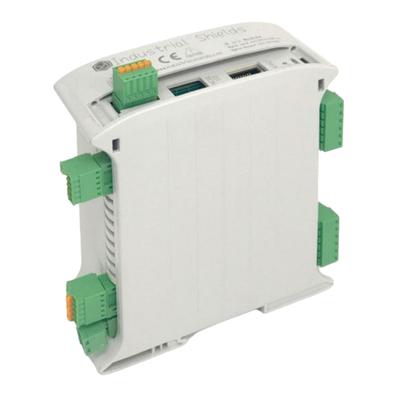
- Page 1 PLC 10 I/Os DIGITAL MODULE CPU ESP32 PLC 10 I/Os DIGITAL MODULE CPU ESP32...
- Page 2 Ref. 013002000100 Rev.0: 0-09-2020...
- Page 3 Ref. 013002000100 Rev.0: 0-09-2020 PLC 10 I/Os Digital Module CPU ESP32 User Guide Revised September 2020 This user guide is for version PLC 10 I/Os Digital Module CPU ESP32 with Reference name Ref. 013002000100.
- Page 4 Rev.0: 0-09-2020 Preface This User Guide is been implemented by Boot & Work, S.L. working under the name Industrial Shields. Purpose of the manual The information contained in this manual can be used as a reference to operate and get a better understanding of the technical data of the signal modules, power supply modules and interface modules.
- Page 5 Ref. 013002000100 Rev.0: 0-09-2020 or electric control room should be limited to authorized personnel. Failure to follow these installation requirements could result in severe personal injury and/or property damage. Always follow these requirements when 10 I/Os family PLCs. • In case of installation or maintenance of the 10 I/Os please follow the instructions marked in the Installation and Maintenance section.
- Page 6 PROPERLY RATED AND INSTALLED FOR THE INTENDED USE WITHIN THE OVERALL EQUIPMENT OR SYSTEM. Industrial Shields shall not be responsible for conformity with any codes, regulations or standards that apply to the combination of products in the customer’s application or use of the product.
- Page 7 Intended use or of Industrial Shields products Consider the following: Industrial Shields products should only be used for the cases of application foreseen in the catalogue and the associated technical documentation. If third-party products and components are used, they must have been recommended or approved by Industrial Shields.
- Page 8 Residual Risks The control and drive components of an Industrial Shields PLC are approved for industrial and commercial use in industrial line supplies. Their use in public line supplies requires a different configuration and/or additional measures. These...
- Page 9 Warranty and Limitations of Liability Warranty Industrial Shields’s exclusive warranty is that the products are free from defects in materials and workmanship for a period of one year (or other period if specified) from date of sale by Industrial Shields.
-
Page 10: Table Of Contents
Ref. 013002000100 Rev.0: 0-09-2020 Table of Contents 10 I/Os Digital Module: General Features ..............10 Technical Specifications .................... 11 General Specifications: ..................11 Performance Specification: ................11 Symbology ......................12 Precautions ........................ 13 ESP32 Board ...................... 13 Intended Audience .................... 13 General Precautions .................. -
Page 11: I/Os Digital Module: General Features
Ref. 013002000100 Rev.0: 0-09-2020 10 I/Os Digital Module: General Features COMPACT PLC 10 I/Os DIGITAL MODULE CPU ESP32 Fuse protection (2.5A) Input Voltage 12 to 24Vdc Polarity protection Input rated voltage 24 Vdc Rated Power 30 W I Max. 1,5A... -
Page 12: Technical Specifications
Ref. 013002000100 Rev.0: 0-09-2020 Technical Specifications General Specifications: Power supply DC power supply 12 to 24Vdc voltage Operating DC power supply 11.4 to 25.4Vdc voltage range Power DC power supply 30 VAC max. consumption Power supply voltage 24Vdc External power supply Power supply output 300 mA capacity... -
Page 13: Symbology
Ref. 013002000100 Rev.0: 0-09-2020 Symbology Table that includes all the symbology that is used in the serigraph of the PLC 10 I/Os Digital Module CPU ESP32: Standard No. / Standard Symbol Standard Title Reference No. / Symbol Meaning Symbol Title... -
Page 14: Precautions
INDUSTRIAL SHIELDS representative. Ensure that the rating and performance characteristics of 10 I/Os Digital Module are sufficient for the systems, machines, and equipment, and be sure to provide the systems, machines, and equipment double safety mechanisms. -
Page 15: Software Interface
Rev.0: 0-09-2020 Software interface Industrial Shields PLC are programmed using Arduino IDE, which is a software based on the C language. They can also be programmed using directly C but it is much easier working with Arduino IDE as it provides lots of libraries that helps in the programming. - Page 16 Ref. 013002000100 Rev.0: 0-09-2020 4. Go to: Tools -> Board: … -> Boards Manager 5. Search for industrialshields. 6. Click install industrialshields-esp32 (selecting the latest version). Following this steps you will be able to use now the Industrial Shields Boards:...
- Page 17 Ref. 013002000100 Rev.0: 0-09-2020 Once it is selected the 10 IOs PLC Family in Industrial Shields ESP32 Family, an extra option will appear on Tools: There, it can be selected the exact model for every family. In this case 10 IOs PLC Digital.
-
Page 18: How To Connect Plc Esp32 To Pc
Rev.0: 0-09-2020 How to connect PLC ESP32 to PC Connect USB port from PLC to PC. NOTE: PLC 10 I/Os Family uses micro USB cable. Open Arduino IDE interface: Select ESP32 Arduino boards -> DOIT ESP32 DEVKIT V1 Select correct port. -
Page 19: How To Connect Plc To Power Supply
DIN Rail: -12Vdc / 24Vdc -2.5A -30W Industrial Shields power supplies provide parallel operation, overvoltage protection, and overcurrent protection. There is a LED inductor for power status, the power supply is certified according to UL. The standard, Part 1 of IEC 61010, sets the general safety requirements for the following types of electrical devices and their accessories, regardless of where use of the device is intended. -
Page 20: I/Os Digital Module Pinout
Ref. 013002000100 Rev.0: 0-09-2020 10 I/Os Digital Module pinout: Left Zone Connections Output Pins Q 0.9 Digital Output Q 0.8 Digital Output Q 0.7 Digital Output Q 0.6 Digital Output Q 0.5 Digital Output Q 0.4 Digital Output Q 0.3 Digital Output Q 0.2 Digital Output... -
Page 21: Right Zone Connections
Ref. 013002000100 Rev.0: 0-09-2020 Right Zone Connections Input Pins I 0.9 Digital Input I 0.8 Digital Input I 0.7 Digital Input I 0.6 Digital Input I 0.5 Digital Input Common GND GNDCOM2 Ground I 0.4 Digital Input I 0.3 Digital Input I 0.2 Digital Input I 0.1... -
Page 22: Top Zone Connections
Ref. 013002000100 Rev.0: 0-09-2020 Top Zone Connections NOTE: In case you need to activate the reset button, it can be found by opening the top cover and accessing the white reset button of the ESP32 board integrated inside de enclosure. NOTE: The LEDs positioned at the top of the PLC, which go from led 0 to 9 refer to both inputs and outputs. -
Page 23: Jumper Configuration
Ref. 013002000100 Rev.0: 0-09-2020 Jumper configuration General jumper configuration The 10 I/Os Digital Module provide 10 digital pins that can act as both input and output. However, they can only be working as one option at a time, so if their function is wished to be changed the jumpers must be adjusted. - Page 24 Ref. 013002000100 Rev.0: 0-09-2020 Warning! Outputs: if the pin is working as output, its jumper of Zone 3 must be connected as the 3.3 – 24 V option. Inputs: if the pin is working as input, DO NOT connect the jumper if you are using a power supply voltage of 230V as it will damage the device and could burn it.
- Page 25 Ref. 013002000100 Rev.0: 0-09-2020...
-
Page 26: I/Os Configuration Examples
Ref. 013002000100 Rev.0: 0-09-2020 I/Os Configuration examples Input mode Low voltage This is an exemple to configure 0.9 as an input with the 3.3-24V current range. - Page 27 Ref. 013002000100 Rev.0: 0-09-2020 High voltage This is an exemple to configure 0.9 as an input with the 230V current range.
- Page 28 Ref. 013002000100 Rev.0: 0-09-2020 Output mode Low voltage This is an exemple to configure 0.9 as an output with the 3.3-24V current range.
-
Page 29: I/Os Communications
RS-485 communication. In the following photo you can see the internal schematic of the PLC of the connection between ESP32 pins, the RS-485 chip and its outputs. Using the boards of Industrial Shields, there is a library that simplifies the RS-485 implementation. - Page 30 Ref. 013002000100 Rev.0: 0-09-2020 General Specifications: Wi-Fi • 802.11 b/g/n • 802.11 n (2.4 GHz), up to 150 Mbps Bluetooth • Bluetooth 4.2 BR/EDR BLE dual mode controller • +12 dBm transmitting power • NZIF receiver with -97 dBm BLE sensitivity...
-
Page 31: Typical Connections
Ref. 013002000100 Rev.0: 0-09-2020 Typical Connections 3.3 - 24v... -
Page 32: Connector Details
Ref. 013002000100 Rev.0: 0-09-2020 Connector details The connector inside the PLCs that mounts on the PCB is MC 0,5/6-G-2,5 THT – 1963502 from Phoenix contact. MC0,5/6-G-2,5THT & MC0,5/5-G-2,5THT Connection details: MC 0,5/6-G-2,5 THT Article reference Height 8,1mm Pitch 2,5mm Dimension 22,5mm Pin dimensions 0,8x0,8mm... -
Page 33: I/Os Family Dimensions
Ref. 013002000100 Rev.0: 0-09-2020 10 I/Os Family Dimensions: 45mm width DIN rail mounting:... -
Page 34: Installation And Maintenance
Ref. 013002000100 Rev.0: 0-09-2020 Installation and Maintenance Notes for installation: The installation position should be free from the following: dust or oil smoke, conductive dust, corrosive or flammable gas, high temperature, condensation, and rain. Besides, vibration and impact also affect the PLC normal operation and shorten its lifespan;... - Page 35 Ref. 013002000100 Rev.0: 0-09-2020 Provide adequate clearance for cooling and wiring 10 I/Os Digital Module. Is designed for natural convection cooling. For proper cooling, you must provide a clearance of at least 25 cm above and below the devices. Also, allow at least 25 cm of depth between the front of the modules and the inside of the enclosure.
- Page 36 Ref. 013002000100 Rev.0: 0-09-2020 - Disconnect the external power supply of the system (on all phases) before connecting or disconnecting a module. Failure to observe this precaution may cause faults or malfunctions of the module. - Tighten the screws of the terminal ports and the screws of the connectors within the prescribed tightening torque.
-
Page 37: Revision Table
Ref. 013002000100 Rev.0: 0-09-2020 Revision Table Revision Number Date Changes 21/09/2020 First implementation... - Page 38 Ref. 013002000100 Rev.0: 0-09-2020 About Industrial Shields: Direction: Fàbrica del Pont, 1-11 Zip/Postal Code: 08272 City: Sant Fruitós de Bages (Barcelona) Country: Spain Telephone: (+34) 938 760 191 / (+34) 635 693 611 Mail: industrialshields@industrialshields.com...
Need help?
Do you have a question about the PLC 10 and is the answer not in the manual?
Questions and answers