Table of Contents
Advertisement
Quick Links
A5S1...-n
Manual
Ex nA Sensors Series A5S1...-n (non-sparking)
(Original operating manual)
valid for versions
A5S1DD0...-n
(1x speed,
A5S1DD3...-n
(1x speed / 1x direction,
A5S1DD4...-n
(2x speed, phase shifted, signal range 0 Hz...25 kHz)
A5S1DS0...-n
(1x speed,
A5S1DS3...-n
(1x speed / 1x direction,
A5S1DS4...-n
(2x speed, phase shifted, signal range 0 Hz...12 kHz)
(valid from Serial-No. 1602050001)
based on Differential-Hall-Effect Principle
signal range 0 Hz...25 kHz)
signal range 0 Hz...25 kHz)
signal range 0 Hz...12 kHz)
signal range 0 Hz...12 kHz)
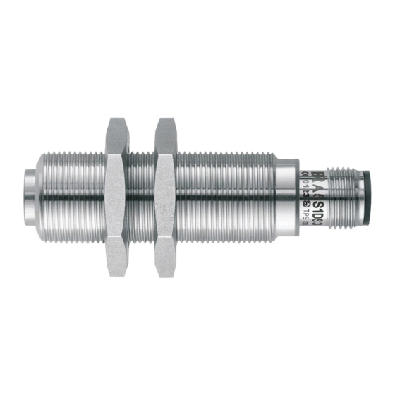
A5S view
(version A5S1DS0M2210B48-n shown)
Speed Sensors
for Hazardous Areas zone 2
TÜV certified for IEC 61508:2010; SIL 3
DIN EN ISO 13849-1:2016; PL e; Kat. 3
DIN EN ISO 13849-2:2012; PL e; Kat. 3
IEC 62061:2015; SIL
A5S1-n-Manual_EN_Rev02
3
CL
2021_JAN_19
Page 1 of 36
Advertisement
Table of Contents

Related Manuals for Braun A5S1-n Series


Summary of Contents for Braun A5S1-n Series
- Page 1 A5S1…-n Manual Ex nA Sensors Series A5S1…-n (non-sparking) (Original operating manual) valid for versions A5S1DD0…-n (1x speed, signal range 0 Hz…25 kHz) A5S1DD3…-n (1x speed / 1x direction, signal range 0 Hz…25 kHz) A5S1DD4…-n (2x speed, phase shifted, signal range 0 Hz…25 kHz) A5S1DS0…-n (1x speed, signal range 0 Hz…12 kHz)
-
Page 2: Table Of Contents
1.4.2.2 Recommended Air Gap ........................7 1.4.3 Maximum fastening torques / wrench sizes / thickness of BRAUN nuts ..........7 Connection (pin assignment resp. wire assignment) ................... 8 Arrangement of Pins in Sensor Plug ......................8 Signal Transmission ............................ 9 Direction of rotation signal for sensor series A5S1DD3…-n / A5S1DS3…-n .......... -
Page 3: General Information
Connection ..............................33 Permissible Ambient Temperature ......................33 Installation Dimensions ..........................33 4.10 Cable diameters of BRAUN Cables ......................34 4.11 Weight ............................... 34 Accessories (optional) ............................. 34 Useful Lifetime, Proof Test Interval and replacement of A5S sensors ............34 Dimensions at different Connection Types .................... -
Page 4: List Of Abbreviations
Abbreviation Meaning altern. alternative Technical standards of the "American Petroleum Institute" BRAUN GmbH Sensor series ATEX stands for ATmosphère Explosibles (meaning the ATEX EU directives for explosion protection) German Institute for Standardisation (Deutsches Institut für Normung) Electromagnetic compatibility European Norm Ex nA Type of protection "non-sparking", approval for hazardous areas zone 2... -
Page 5: Application Characteristics
Application characteristics Speed sensors for applications such as turbines, compressors, expanders, etc. in hazardous areas of zones 2. The sensors are approved as “non-sparking/non-incendive” equipment with protection class Ex nA IIC, temperature class T4 (at Ta = -40 ° C to +125 ° C) or temperature class T6 (at Ta = -20 °... -
Page 6: Notes On Pole Wheel
1.4.1 Notes on Pole Wheel The pole wheel must be made of ferromagnetic steel. Non-ferrous material, stainless steel or plastics do not work. The grooves / bolts of the pole wheel must be equidistant; otherwise the speed signal will be unsteady. -
Page 7: Recommended Air Gap
0.3 – 1.2 mm 6.35 mm 3 mm 1.0 – 2.5 mm 0.5 – 1.5 mm 1.4.3 Maximum fastening torques / wrench sizes / thickness of BRAUN nuts Maximum thickness wrench size fastening torque (+/- 0.5 mm) M12 x 1... -
Page 8: Connection (Pin Assignment Resp. Wire Assignment)
All sensors described here can have different dimensions and different connection types. For the connections applies to the different types: Assignment with plug with open cable ends of pin no. BRAUN cables wire color Signal output 1: white (speed signal f1) Common zero... -
Page 9: Signal Transmission
Signal Transmission The possible transmission distance is essentially determined by the highest occurring signal frequency, the properties of the transmission line and the input of the connected receiving device. When connected to our equipment for fixed installation, signal frequency of 25000 Hz can be safely transmitted over a distance of up to 500 m. -
Page 10: Direction Of Rotation Signal For Sensor Series A5S1Dd3
Direction of rotation signal for sensor series A5S1DD3…-n / A5S1DS3…-n The sensor indicates the direction of rotation by a constant signal, which is either high or low depending on the direction (see below for level values). The change is instantaneous as soon as a pole pitch (e.g., 1 tooth) has passed the sensor. -
Page 11: Level And Shape Of The Output Signal
1.10 Level and shape of the output signal Rectangular pulses at low frequencies and with short lines. At higher frequencies and with long lines, the signal at the receiver becomes a saw tooth tread profile. Pulse pitch depends on the profile shape, when sampling a gear wheel profile, it is about 1:1. The level is the same over the entire speed range. -
Page 12: Ordering Key For Sensors Of A5S1
1.11 Ordering Key for Sensors of A5S1…-n Series A5S1 b c d e f g - I -n Signal frequency Cable length in meters DD : 0 Hz…25 kHz 1m to 99m* DS : 0 Hz…12 kHz *only with versions with fixed cable Signal output Nominal thread length in mm 0 : 1x frequency... -
Page 13: Safety Data
The A5S… series differential hall effect sensors are TÜV certified according to IEC 61508:2010; suitable up to SIL3 as stand-alone speed sensors for the functions: • speed monitoring in connection with BRAUN E16 machine protection systems • output of a correct speed signal (frequency) with an accuracy of +/- 1Hz 1.13.2... -
Page 14: Sil 3 Certificate
1.13.5 SIL 3 Certificate Figure 4: SIL 3 Certificate A5S1-n-Manual_EN_Rev02 2021_JAN_19 Page 14 of 36... -
Page 15: Eu Declaration Of Conformity
Unbedingte Beachtung aller Punkte der mitgelieferten Betriebsanleitung ist hierbei Voraussetzung. Strict observance of the operation manual is an indispensable precondition, hereto. Unterzeichnet für und im Namen der BRAUN GmbH / Signed for and on behalf of BRAUN GmbH Waiblingen, 19-JAN-2021... -
Page 16: Hazardous Protection
Hazardous protection The safety requirements as determined by EN 1127-1, as well as the corresponding national regulations, are to be complied with regarding primary explosion protection, i.e. measures which prevent or restrict the formation of a hazardous explosive atmosphere. In the case of secondary hazardous protection, i.e. measures that prevent the ignition of an explosive atmosphere surrounding electrical equipment, the series of standards applicable to EN 60079 and the relevant national regulations must be observed. -
Page 17: Atex Type Examination Certificate
2.3.5 ATEX Type Examination Certificate Figure 6: ATEX Type Examination Certificate part 1 A5S1-n-Manual_EN_Rev02 2021_JAN_19 Page 17 of 36... - Page 18 Figure 7: ATEX Type Examination Certificate part 2 A5S1-n-Manual_EN_Rev02 2021_JAN_19 Page 18 of 36...
- Page 19 Figure 8: ATEX Type Examination Certificate part 3 A5S1-n-Manual_EN_Rev02 2021_JAN_19 Page 19 of 36...
-
Page 20: Iecex Certificate Of Conformity
2.3.6 IECEx Certificate of Conformity Figure 9: IECEx Certificate of Conformity part 1 A5S1-n-Manual_EN_Rev02 2021_JAN_19 Page 20 of 36... - Page 21 Figure 10: IECEx Certificate of Conformity part 2 A5S1-n-Manual_EN_Rev02 2021_JAN_19 Page 21 of 36...
- Page 22 Figure 11: IECEx Certificate of Conformity part 3 A5S1-n-Manual_EN_Rev02 2021_JAN_19 Page 22 of 36...
- Page 23 Figure 12: IECEx Certificate of Conformity part 4 A5S1-n-Manual_EN_Rev02 2021_JAN_19 Page 23 of 36...
- Page 24 Figure 13: IECEx Certificate of Conformity part 5 A5S1-n-Manual_EN_Rev02 2021_JAN_19 Page 24 of 36...
- Page 25 Figure 14: IECEx Certificate of Conformity part 6 A5S1-n-Manual_EN_Rev02 2021_JAN_19 Page 25 of 36...
-
Page 26: Nec/Cec Certificate Of Conformity
2.3.7 NEC/CEC Certificate of Conformity Figure 15: NEC/CEC Certificate of Conformity part 1 A5S1-n-Manual_EN_Rev02 2021_JAN_19 Page 26 of 36... - Page 27 Figure 16: NEC/CEC Certificate of Conformity part 2 A5S1-n-Manual_EN_Rev02 2021_JAN_19 Page 27 of 36...
-
Page 28: Eac Ex Tr Cu Certificate
2.3.8 EAC Ex TR CU Certificate Figure 17: EAC Ex TR CU Certificate part 1 A5S1-n-Manual_EN_Rev02 2021_JAN_19 Page 28 of 36... - Page 29 Figure 18: EAC Ex TR CU Certificate part 2 A5S1-n-Manual_EN_Rev02 2021_JAN_19 Page 29 of 36...
- Page 30 Figure 19: EAC Ex TR CU Certificate part 3 A5S1-n-Manual_EN_Rev02 2021_JAN_19 Page 30 of 36...
- Page 31 Figure 20: EAC Ex TR CU Certificate part 4 A5S1-n-Manual_EN_Rev02 2021_JAN_19 Page 31 of 36...
-
Page 32: Safety Notes For Installation And Operation
Safety Notes for Installation and Operation General Instructions The sensors of series A5S1…-n are built and tested according to standards DIN EN 61010-1 (VDE 0411-1) and have left the factory in a perfectly safe condition. To maintain this condition and to ensure safe operation, the user must follow the instructions contained in this manual. Connection and maintenance work may only be performed by adequately qualified personnel and only when the power supply is switched off. -
Page 33: Technical Specifications
Current consumption: approx. 15 mA (one channel sensor) resp. 25 mA (two channel sensor), plus load (can increase up to 60 mA with long transmission length and high signal frequency). If power supply isn’t provided by a BRAUN device, a PELV resp. SELV power supply has to be used. -
Page 34: Cable Diameters Of Braun Cables
4.10 Cable diameters of BRAUN Cables PVC 3-wire (LiYCY 3x0.5 mm ) : approx. 5.4 mm (+/- 0.5 mm) PVC 4-wire (LiYCY 4x0.5 mm ) : approx. 5.8 mm (+/- 0.5 mm) Teflon ® 3-wire (LiTCT 3x0.5 mm ) : approx. 4.8 mm (+/- 0.5 mm) Teflon ®... -
Page 35: Dimensions At Different Connection Types
Dimensions at different Connection Types 65 mm Sensor with screwed on straight mating connector 50 mm Sensor with screwed on angled mating connector 55 mm 20 mm approx. 30 mm Sensor with fix mounted connecting cable 32 mm approx. 30 mm Sensor (NPT version) with 5/8"-18 fixed Teflon... -
Page 36: Revision Notes
Max. supply current: see certificates from chapter 2.3. 19.01.2021 Editorial: EU Declaration of Conformity in chapter 1.13.6 adapted. Quality certified acc. to ISO 9001 D 71334 Waiblingen-Hegnach Esslinger Str. 26 Phone: +49 (0)7151/956230 Fax: +49 (0)7151/956250 E-Mail: info@braun-tacho.de Internet: www.braun-tacho.de A5S1-n-Manual_EN_Rev02 2021_JAN_19 Page 36 of 36...
Need help?
Do you have a question about the A5S1-n Series and is the answer not in the manual?
Questions and answers