
Related Manuals for Miller MigMatic Cooler


Summary of Contents for Miller MigMatic Cooler
- Page 1 OM-287469A 2020-05 Processes MIG (GMAW) Welding Description MigMatic Cooler OWNER’S MANUAL For product information, Owner’s Manual translations, and more, visit www.MillerWelds.com...
- Page 2 From Miller to You Thank you and congratulations on choosing Miller. Now you can get the job done and get it done right. We know you don’t have time to do it any other way. That’s why when Niels Miller first started building arc welders in 1929, he made sure his products offered long-lasting value and superior quality.
-
Page 3: Table Of Contents
TABLE OF CONTENTS SECTION 1 − SAFETY PRECAUTIONS - READ BEFORE USING ....... . . 1-1. -
Page 5: Section 1 − Safety Precautions - Read Before Using
SECTION 1 − SAFETY PRECAUTIONS - READ BEFORE USING coolers 2020-02 Protect yourself and others from injury — read, follow, and save these important safety precautions and operating instructions. 1-1. Symbol Usage DANGER! − Indicates a hazardous situation which, if Indicates special instructions. -
Page 6: California Proposition 65 Warnings
READ INSTRUCTIONS. HIGH PRESSURE FLUIDS can injure or kill. D Read and follow all labels and the Owner’s D Coolant can be under high pressure. Manual carefully before installing, operating, or D Release pressure before working on cooler. servicing unit. Read the safety information at the beginning of the manual and in each D If ANY fluid is injected into the skin or body seek medical help section. -
Page 7: Section 2 − Definitions
SECTION 2 − DEFINITIONS 2-1. Additional Safety Symbols And Definitions Some symbols are found only on CE products. Warning! Watch Out! There are possible hazards as shown by the symbols. Safe1 2012−05 Do not discard product (where applicable) with general waste. Reuse or recycle Waste Electrical and Electronic Equipment (WEEE) by disposing at a designated collection facility. -
Page 8: Miscellaneous Symbols And Definitions
Plugged filter or hoses can cause overheating to the power source and torch. Safe50 2012−05 100 h. Std. Every 100 hours, check and clean filter and check condition of hoses. Safe51 2012−05 2-2. Miscellaneous Symbols And Definitions Read Operator’s Amperage Remote Manual Suitable for... -
Page 9: Section 3 − Specifications
SECTION 3 − SPECIFICATIONS 3-1. Serial Number And Rating Label Location The serial number and rating information for this product is located on the back panel. Use rating label to determine input power requirements and/or rated output. For future reference, write serial number in space provided on cover of this manual. 3-2. -
Page 10: Section 4 − Installation
SECTION 4 − INSTALLATION 4-1. Tipping Do not move or operate unit where it could tip. Loc_cooler 2016-08 4-2. Selecting a Location Position unit so air can circulate. 18 in. 18 in. (460 mm) (460 mm) 18 in. (460 mm) 956172376_1-A OM-287469 Page 6... -
Page 11: Installing Cooler On Migmatic Welding Power Source
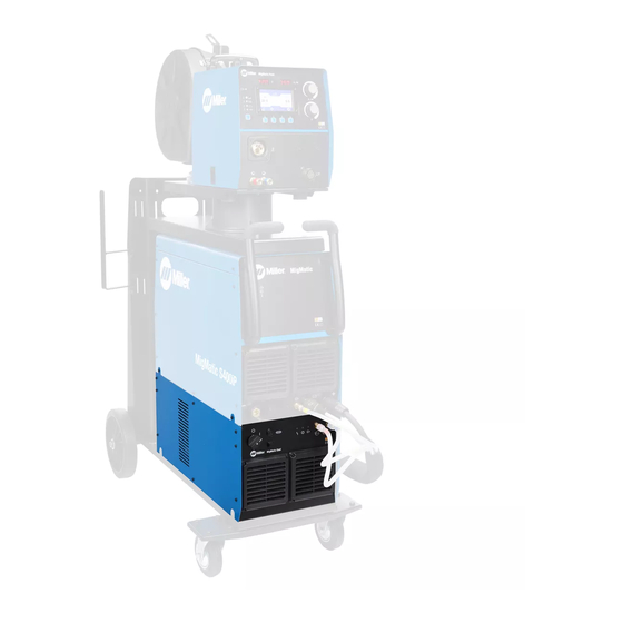
4-3. Installing Cooler On MigMatic Welding Power Source Turn Off welding power source. Disconnect input power before in- stalling cooler on welding power source. Welding Power Source Cooler Screws Place power source on cooler and secure with screws. Tools Needed: m30 Torx 956172376_2-A OM-287469 Page 7... -
Page 12: Cooler Connections
4-4. Cooler Connections 400 volt, 1 Amp AC Receptacle 400 volts AC Cord Provides 115 VAC to power cooler. 7-Pin Receptacle (See Section 4-5) Provides the following signals: • Signal to activate the cooler • Check for the presence of coolant flow •... -
Page 13: Section 5 − Operation
SECTION 5 − OPERATION 5-1. Front Panel Controls Power Switch S1 Pump Priming Push Button Input Power Line 2A Fuse Water Flow Alarm Indicator Light Cooler Operation Indicator Light Input Line Voltage Water In Quick Connect Water Out Quick Connect Ref. -
Page 14: Section 6 − Maintenance & Troubleshooting
SECTION 6 − MAINTENANCE & TROUBLESHOOTING 6-1. Routine Maintenance Disconnect power before maintaining. n = Check Z = Change ~ = Clean l = Replace Reference * To be done by Factory Authorized Service Agent Every NOTICE − Clean coolant filter. Severe condi- tions may require more frequent cleaning (con- Months tinuous use, high/low temperatures, dirty envi-... -
Page 15: Section 7 − Electrical Diagram
SECTION 7 − ELECTRICAL DIAGRAM Ref. 956172383-A OM-287469 Page 11... -
Page 16: Section 8 − Parts List
SECTION 8 − PARTS LIST Hardware is common and not available unless listed. 956172376_4-A Figure 8-1. Main Assembly, MigMatic Cool OM-287469 Page12... - Page 17 Item Dia. Part Mkgs. Description Figure 8-1. Main Assembly, MigMatic Cool ....116170004 Grid, Front ............
- Page 18 Notes OM-287469 Page 14...
- Page 19 Effective January 1, 2020 (Equipment with a serial number preface of NA or newer) This limited warranty supersedes all previous Miller warranties and is exclusive with no other guarantees or warranties expressed or implied. LIMITED WARRANTY − Subject to the terms and conditions Positioners and Controllers below, Miller Electric Mfg.
- Page 20 File a claim for loss or damage during Fax: +31 (0) 186 640 880 shipment. For assistance in filing or settling claims, contact your distributor and/or equipment manufacturer’s Transportation Department. © ORIGINAL INSTRUCTIONS − PRINTED IN USA 2020 Miller Electric Mfg. LLC 2020−01...
Need help?
Do you have a question about the MigMatic Cooler and is the answer not in the manual?
Questions and answers