
Subscribe to Our Youtube Channel
Related Manuals for VERDER CARBOLITE GERO CWF 11/13


Summary of Contents for VERDER CARBOLITE GERO CWF 11/13
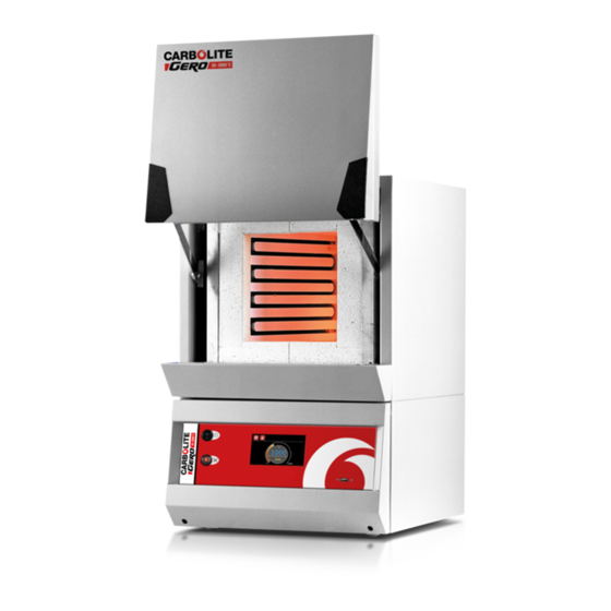
- Page 1 Installation, Operation and Maintenance Instructions 1100°C Chamber Furnace - CWF Model: 13 Litres No Controller CWF 11/13 + No Controller MEN-CWF1113-005_NOCTRL 01-08-2019...
-
Page 2: Table Of Contents
Contents This manual is for guidance on the use of the Carbolite Gero product specified on the front cover. This manual should be read thoroughly before unpacking and using the furnace or oven. The model details and serial number are shown on the back of this manual. - Page 3 Calibration After-Sales Service Recommended Spare Parts and Spare Parts Kit 7.0 Repairs and Replacements Safety Warning - Disconnection from Power Supply Safety Warning - Refractory Fibre Insulation Temperature Controller Replacement Solid-State Relay Replacement Thermocouple Replacement Panel Element Replacement Door Plug Replacement Fuse Replacement 8.0 Fault Analysis Furnace Does Not Heat Up...
-
Page 4: Symbols And Warnings
1.0 Symbols and Warnings 1.0 Symbols and Warnings Switches and Lights Instrument switch: when the instrument switch is operated the temperature control circuit is energised. Heat light: the adjacent light glows or flashes to indicate that power is being supplied to the elements. General Warnings DANGER –... -
Page 5: Installation
2.0 Installation 2.0 Installation Unpacking and Handling When unpacking and handling the product, always lift it by its base. Do not use the door or any other projecting cover or component to support the equipment when moving it. Use two or more people to carry the product where possible. Carefully remove any packing material from inside and around the product before use. -
Page 6: Chimney
2.0 Installation Depending on the application of the product, it may be appropriate to position it under an extraction hood. Ensure the extraction hood is switched on during use. Ensure that the product is placed in such a way that it can be quickly switched off or disconnected from the electrical supply. -
Page 7: Electrical Connections
2.0 Installation Duct (75mm-150mm diameter) Ambient air is drawn into duct Chimney D 25mm vertical gap between chimney and duct Electrical Connections Connection by a qualified electrician is recommended. This product requires a single-phase A.C. supply with earth (ground), which may be Live to Neutral non-reversible (polarised), Live to Neutral reversible (non-polarised), or Live to Live. - Page 8 2.0 Installation Electrical Connection Details: Supply Types Supply Terminal Label Cable Colour Reversible or Live- Live - Neutral Live to either power conductor 1-phase L Brown to live (For USA 200-240V, connect L1) to the other power conductor Blue to neutral (For USA 200-240V, connect L2) to earth...
-
Page 9: Temperature Controller
3.0 Temperature Controller 3.0 Temperature Controller If this product is fitted with a temperature controller, instructions are provided separately. -
Page 10: 2132 Over-Temperature Controller Description (If Fitted)
4.0 2132 Over-Temperature 4.0 2132 Over-Temperature Controller Description (if fitted) Description Alarm Light Page Scroll D Down Display This over-temperature controller is fitted and supplied ready to use by Carbolite Gero. It is a digital instrument with a latching alarm, requiring no additional panel controls. The controller features easy setting of over-temperature setpoint and reading of current temperature by the over-temperature sensor. -
Page 11: Operation
4.0 2132 Over-Temperature 4.2.2 Operation When switched on, the controller lights up, goes through a short test routine and then displays the measured temperature or the over-temperature setpoint. The page key allows access to parameter lists within the controller. A single press of the page key displays the temperature units, normally set to °C;... -
Page 12: Audible Alarm
4.0 2132 Over-Temperature Audible Alarm If an audible alarm is supplied for use with the over-temperature controller, it is normally configured to sound on over-temperature condition and to stop sounding when the alarm is acknowledged as given in section 4.2. Note: the alarm may sound during controller start-up. -
Page 13: Operation
5.0 Operation 5.0 Operation Operating Cycle This product is fitted with an instrument switch which cuts off power to the control circuit. Connect the product to the electrical supply. Turn on the instrument switch to activate the temperature controllers. The controllers illuminate and go through a short test cycle. -
Page 14: Use Of Probes
5.0 Operation Materials such as case hardening compounds and other reactive salts may penetrate the furnace chamber lining and attack the wire elements, causing premature failure. Use of a hearth tile may be advisable: please consult the Carbolite Gero technical department. Use of Probes Any metal object used to probe into the product chamber while the product is connected to the electrical supply must be earthed. -
Page 15: Power Adjustment
5.0 Operation Power Adjustment The product control system incorporates electronic power limiting. Depending on the model and the destination country the power limit maybe set to 100% or a lower figure. Where appropriate the power limit parameter OP.Hi is accessible to the operator, but it should not generally be altered. -
Page 16: Maintenance
6.0 Maintenance 6.0 Maintenance General Maintenance Preventive rather than reactive maintenance is recommended. The type and frequency depends on the product use; the following are recommended. Maintenance Schedule CUSTOMER QUALIFIED PERSONNEL DANGER! ELECTRIC SHOCK. Risk of fatal injury. Only electrically qualified personnel should attempt these maintenance procedures. - Page 17 6.0 Maintenance Operational Check Check that all functions are working normally Thorough inspection and report incor- Operational Check porating a test of all functions Performance Element Circuit Electrical measurement Measure the current drawn on each phase / Power Consumption circuit Hearth Visual check for fit and damage Cooling Fans (if fitted)
-
Page 18: Cleaning
6.0 Maintenance 6.2.1 Cleaning Soot deposits may form inside the furnace, depending on the process. At appropriate intervals remove these by heating as indicated in the General Operation Notes. The product's outer surface may be cleaned with a damp cloth. Do not allow water to enter the interior of the case or chamber. -
Page 19: After-Sales Service
6.0 Maintenance thermocouple and temperature indicator should be made from time to time to determine whether full calibration is required. Carbolite Gero can supply these items. Depending on the controller fitted, the controller instructions may contain calibration instructions. After-Sales Service Carbolite Gero Service has a team of Service Engineers who can offer repair, calibration and preventive maintenance of furnace and oven products both at the Carbolite Gero factory and at customers’... -
Page 20: Repairs And Replacements
7.0 Repairs and Replacements 7.0 Repairs and Replacements Safety Warning - Disconnection from Power Supply Immediately switch the product off in the event of unforeseen circumstances (e.g. large amount of smoke). Allow the product to return to room temperature before inspection. Always ensure that the product is disconnected from the electrical supply before repair work is carried out. -
Page 21: Solid-State Relay Replacement
7.0 Repairs and Replacements Solid-State Relay Replacement Disconnect the product from the power supply and remove the appropriate cover as given above. 1. Make a note of the wire connections to the solid state relay, then disconnect them. 2. Remove the solid state relay from the base panel or aluminium plate. 3. -
Page 22: Panel Element Replacement
7.0 Repairs and Replacements Panel Element Replacement See section 7.2 - wearing a face mask is required. The chambers have two side-mounted refractory panels in which coiled heating elements are inserted and one unheated hearth slab. Disconnect the furnace from the electrical supply and remove the furnace back panel. Make a written plan showing ALL the element and thermocouple connections. - Page 23 7.0 Repairs and Replacements Element A Example Connections B Terminal Block C Link D CWF/23 element connection example (1-phase 200-240V) 5 & 13 litre models Live N Neutral...
-
Page 24: Door Plug Replacement
7.0 Repairs and Replacements Door Plug Replacement See section 7.2 - wearing a face mask is required. Open the door and remove the door cover from the plug carrier assembly. Remove the old door plug by sliding it upwards out of its carrier. Slide the new plug into the carrier assembly making sure that the plug is the correct way Refit the door cover. - Page 25 7.0 Repairs and Replacements If any fuse has failed, it is advisable for an electrician to check the internal circuits. Replace any failed fuses with the correct type. For safety reasons do not fit larger capacity fuses without first consulting Carbolite Gero. The fuses are located at the cable entry point.
-
Page 26: Fault Analysis
8.0 Fault Analysis 8.0 Fault Analysis Furnace Does Not Heat Up The HEAT The heating element Check also that the SSR is working light is ON has failed correctly The controller shows a The HEAT The thermocouple has broken or has very high temperature light is OFF a wiring fault... -
Page 27: Product Overheats
8.0 Fault Analysis Product Overheats Product only heats up The controller when the instrument shows a very high The controller is faulty switch is ON temperature The thermocouple may be The controller faulty or may have been shows a low removed out of the heating temperature chamber... -
Page 28: Wiring Diagrams
9.0 Wiring Diagrams 9.0 Wiring Diagrams WA-11-30 Connections below show single phase with indirect safety switch(es). F1, F2, F3 Fuses Filter R1/1, R1/2 Relay Contactor Relay Cables Temperature Controller Blue Control Thermocouple Solid State Relay GR/Y Green + Yellow Safety Switch Grey Heat Lamp Pink... - Page 29 9.0 Wiring Diagrams WA-11-31 Connections below show single phase with safety switches and over-temperature control. F1, F2, F3 Fuses Filter R1/1, R1/2 Relay Contactor Relay Temperature Controller Cables Over-Temperature Controller Blue Over-Temperature Thermocouple Control Thermocouple GR/Y Green + Yellow Solid State Relay Grey Safety Switch Pink...
- Page 30 9.0 Wiring Diagrams WA-22-30 Connections below show 2-phase +N with indirect safety switches. F1, F2, F3 Fuses Filter R1/1, R1/2 Relay Contactor Relay Cables Temperature Controller Blue Control Thermocouple Solid State Relay GR/Y Green + Yellow Safety Switch Grey Heat Lamp Pink Element(s) Instrument Switch(es)
-
Page 31: Fuses And Power Settings
10.0 Fuses and Power Settings 10.0 Fuses and Power Settings 10.1 Fuses F1 - F3: Refer to the circuit diagrams. GEC Safeclip of the type shown Fitted if supply cable fitted. Internal (glass type F up to 16 A) Supply Fitted on board to some types 38 mm x 10 mm type F fitted on Fuses... -
Page 32: Specifications
11.0 Specifications 11.0 Specifications Carbolite Gero reserves the right to change the specification without notice. Chamber Size Approx (mm) Model Temp Power Weight Capacity (l) (°C) (kW) (kg) Chamber furnaces heated by coiled resistance wire inserted into refractory formers. CWF 11/13 1100 11.1 Environment... - Page 33 Notes Service Record Engineer Name Date Record of Work...
- Page 34 The products covered in this manual are only a small part of the wide range of ovens, chamber furnaces and tube furnaces manufactured by Carbolite Gero for laboratory and industrial use. For further details of our standard or custom built products please contact us at the address below, or ask your nearest stockist.
Need help?
Do you have a question about the CARBOLITE GERO CWF 11/13 and is the answer not in the manual?
Questions and answers