Table of Contents
Advertisement
Advertisement
Table of Contents

Summary of Contents for Varex Imaging Claymount Optica 20 Series
- Page 1 Optica 20 series 1639 User Manual www.vareximaging.com UM50845-EN, Revision: 3.0...
- Page 2 This page is deliberately left blank. User Manual UM50845-EN Optica 20 series Revision: 3.0 2/28 www.vareximaging.com Date of release: 2019-12-03...
-
Page 3: Table Of Contents
Table of Contents Introduction ..............................6 1.1. Contact information ..........................6 1.2. Abbreviations, acronyms and definitions ................... 6 1.3. Symbols used in this document ......................7 1.4. Advisory.............................. 7 Radiation danger ............................7 1.5. General warnings, cautions and notes ....................8 1.6. - Page 4 Figure 1: Device, Front view ..........................13 Figure 2: Device, Bottom view ........................... 14 Figure 3: Accessory rail specification ........................ 15 Figure 4: Main dimensions ..........................16 Figure 5: Shutter control ............................ 19 Figure 6: Laser shutter(s) ..........................20 Figure 7: Filter module ............................21 Figure 8: Back view (product label) ........................
- Page 5 Although this manual is prepared with utmost care, Varex Imaging Nederland B.V. cannot be held accountable for errors or omissions. Varex Imaging Nederland B.V. cannot be held accountable for damages of any nature arising from the use, and / or use of any options other than original Varex Imaging Nederland B.V. products.
-
Page 6: Introduction
This manual provides all the technical information necessary for the correct installation, application, operation, maintenance and service of the device. If you need additional information, need support or want to report a problem with the device, please contact your distributor or Varex Imaging Nederland B.V.: Manufacturer Distributor Name Varex Imaging Nederland B.V. -
Page 7: Symbols Used In This Document
• The Optica 20 series is not subjected to regular inspection and maintenance. • Use of the Optica 20 series in a way which could not be reasonable foreseen by Varex Imaging Nederland B.V.. • Direct or indirect damage which are caused by not following the procedures and instructions in this manual. -
Page 8: General Warnings, Cautions And Notes
WARNING: When there is any damage to the collimator or repair is needed, only original replacement parts shall be used. Contact your distributor or Varex Imaging Nederland B.V. for assistance. WARNING: Portable RF communications equipment (including peripherals such as antenna cables and external antennas) should be used no closer than 30 cm (12 inches) to any part of the Optica 20 series, including cables specified by the manufacturer. -
Page 9: Labels And Markings On The Device
Requirements for SERVICE PERSONNEL The device may only be installed, repaired or serviced by qualified SERVICE PERSONNEL, i.e.: • Authorized by the RESPONSIBLE ORGANIZATION of the device; • Authorized by the manufacturer; • In possession of the diploma’s / certificates required by national and local legislation. WARNING: Service, maintenance and adjustments may only be executed by qualified SERVICE PERSONNEL. - Page 10 Symbol Explanation Warning: Laser emission, possibly hazardous optical radiation emission Identifies the exit point of the laser beam (optional feature) GROUPE DE RISQUE 2 RISK GROUP 2 ATTENTION. Il est possible que ce produit émette des rayonnements optiques dangereux. Explanatory warning for hazardous optical radiation Ne pas fixer la lampe pendant son fonctionnement.
-
Page 11: Supplied Components
Conformity • 1 Terminal adapter Content depends on the model as described above Be advised by your distributor or Varex Imaging Nederland B.V. for any accessories available. See also §6.3. User Manual UM50845-EN Optica 20 series Revision: 3.0 11/28 www.vareximaging.com... -
Page 12: Device Description
2. Device description This chapter will describe the device in general and detail. The device is pointed out with features present in §2.4. Classifications of the device are listed in §2.11. 2.1. INTENDED USE The device is intended to be used in medical diagnostic applications with restrictions to human diagnostics. The device is intended to be used as accessory of an X-ray system in a professional healthcare facility environment. -
Page 13: Principle Of Operation
2.3. Principle of operation The operable features to perform the INTENDED USE of the collimator are positioned on the front of the collimator. The following table shows symbols that are used to indicate the operable features: Symbol Definition Description Cross shutters The bold lines indicate the shutter pair seen from the top-side of the collimator. - Page 14 Accessory rails Single laser aperture SID tape shutter measure Single laser aperture Accessory retaining latch / lock spring Figure 2: Device, Bottom view User Manual UM50845-EN Optica 20 series Revision: 3.0 14/28 www.vareximaging.com Date of release: 2019-12-03...
- Page 15 Accessory rail specifications Maximum accessories: 2 Maximum allowed total weight of accessories: 2 kg per Optica 20 series device. Accessory rail interface dimensions, see also figure below Width (d1): 176 – 177 mm Thickness (d2): Max 2.3 Pitch between slots (d3): 4.5 mm Length (d4): max.
-
Page 16: Main Dimensions
2.5. Main dimensions Figure 4: Main dimensions 2.6. Aluminum equivalent The Aluminum equivalent (or ATTENUATION EQUIVALENT) can be found on the product label. The location of the product label can be found in §6.2. The ATTENUATION EQUIVALENT is expressed in [mm] aluminum. 2.7. -
Page 17: Classifications
Classifications 2.11. Subject Classification Reference Electrical safety Class I IEC 60601-1 Electromagnetic Compatibility Professional healthcare facility IEC 60601-1-2 intended environment environment Mode of operation Continuous IEC 60601-1 Ingress protection IP20 IEC 60529 Laser Class 2 IEC 60825-1 Field light Risk Group 2 IEC 62471 Not intended for use in Oxygen Rich environment. -
Page 18: Operating Instructions
3. Operating instructions This chapter describes the operating instructions. Powering ON and OFF are described in §3.1. The status LED colors are clarified in §3.2. A description of features to perform the INTENDED USE is given in §3.3. 3.1. Switching the device ON and OFF The collimator does not have a switch to power on/off the device. -
Page 19: Device Features
3.3. Device features This section describes the features which can be present on the collimator. Depending on the configuration of the collimator some features may be unavailable. The following figures show a generic model, characteristics like layout, color and available features can be different. A. - Page 20 Push button for light field indicator, a green indication LED will light above the button. The light will be activated for a pre-defined time and will switch off automatically. Push the button again to switch off the light field. Push button for activating single line laser. The laser will be activated for a pre-defined time and will switch off automatically.
-
Page 21: Adjustments
G. Accessory rails, suitable for holding maximum of two accessories. See also §2.4. H. Lock spring for accessories; slightly pull out the spring and remove the applicable accessory. See also §2.4. NOTE: Be careful when handling the lock spring, over-elongating the spring can cause permanent damage to the lock spring. -
Page 22: Emc Compatibility
3.5. EMC compatibility The device conforms to EN IEC 60601-1-2:2015 for EMC compatibility and must be used according to the EMC information provided in this manual. WARNING: Use of this equipment adjacent to or stacked with other equipment should be avoided because it could result in improper operation. -
Page 23: Troubleshooting, Maintenance And Service
4. Troubleshooting, maintenance and service This chapter describes troubleshooting, cleaning, maintenance and service. 4.1. Troubleshooting Information about troubleshooting can be found in the Technical Manual (see TM50844). 4.2. Cleaning Cleaning procedures and agents Follow local, national and organizational procedures regarding cleaning. The following agents are safe to use: Agents Isopropanol Ethyl alcohol... -
Page 24: Disposal
5. Disposal This device contains substances that can be hazardous to the environment and care should be taken when disposed of. The device is marked with the following symbol: Follow national and local regulations regarding disposal of electronic equipment. Packaging material shall be recycled according national and local regulations. User Manual UM50845-EN Optica 20 series Revision: 3.0... -
Page 25: Specifications And Accessories
6. Specifications and accessories This chapter gives specifications (technical and product label information) and information about available accessories. 6.1. Technical specifications Classifications See section 2.11 Application Stationary equipment for radiography (see §2.1) ABS/PC, PC, POM, stainless steel, aluminum, lead, glass, brass, Materials (spring) steel Power source... -
Page 26: Product Label
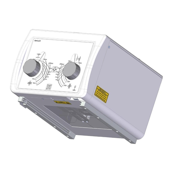
The product label is located on the back-side of the collimator: Product label area Figure 8: Back view (product label) WARNING: If the product label is missing or not readable contact your distributor or Varex Imaging Nederland B.V. User Manual UM50845-EN Optica 20 series Revision: 3.0 26/28 www.vareximaging.com... -
Page 27: Accessories
The product label as shown in Figure 9 is representing the layout. The attached label on the collimator shows the specific information valid for your device. 6.3. Accessories Be advised by your distributor or Varex Imaging Nederland B.V. for any accessories available. The following accessories are available (see TM50844): 1. Screw terminal adapter accessory 2. - Page 28 F +63 2 80764 72 Philippines.CNC@vareximaging.com © 2019 by Varex Imaging Nederland B.V. All Rights reserved. No part of this document may be reproduced or transmitted in any form or by any means, electronic, mechanical, photocopying, recording, or otherwise, without prior written permission of Varex Imaging Nederland B.V..
Need help?
Do you have a question about the Claymount Optica 20 Series and is the answer not in the manual?
Questions and answers