Table of Contents
Advertisement
Quick Links
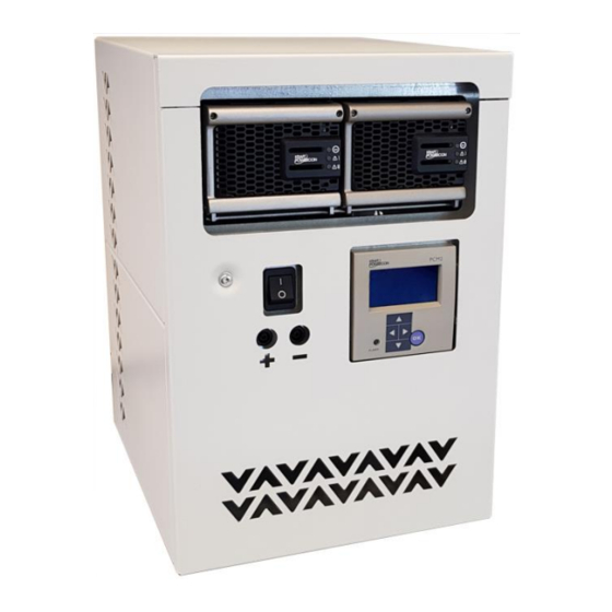
charging rectifier
You must read this manual before installation, use or work on the product.
This product contains dangerous voltage that when touched can cause electric shock, burns
or death.
The product must be installed by qualified personnel and according to the installation
instructions. Service may only be performed by authorised service personnel. The equipment
may only be opened by qualified personnel. Work in addition to replacing the rectifier modules
may only be carried out when all power has been cut to the equipment and when the mains
breaker has been closed for at least five minutes. The protective covers and contact safety
devices inside the equipment may only be removed by authorised service personnel.
The power must always be disconnected in a safe way before starting any
service/maintenance.
WARNING! Multiple power sources. Dangerous voltage is possible even with mains power
shut off. The panel mains power switch does not give a dead condition.
KraftPowercon Sweden AB, Hjalmar Petris väg 49, 352 46 Växjö, Sweden, Tel: 0470-705200, Fax: 0470-705201,
Manual for
type PRX
SAFETY INSTRUCTIONS
www.kraftpowercon.com
Dokumentnr: 9-1719-B
Artikelnr: 0001137
Advertisement
Table of Contents

Related Manuals for Kraft Powercon PRX Series

Summary of Contents for Kraft Powercon PRX Series
- Page 1 Manual for charging rectifier type PRX SAFETY INSTRUCTIONS You must read this manual before installation, use or work on the product. This product contains dangerous voltage that when touched can cause electric shock, burns or death. The product must be installed by qualified personnel and according to the installation instructions.
- Page 2 Vi förbehåller oss rätten till ändringar av innehållet utan föregående avisering. KraftPowercon Sweden AB, Hjalmar Petris väg 49, 352 46 Växjö, Sweden, Tel: 0470-705200, Fax: 0470-705201, www.kraftpowercon.com...
-
Page 3: Table Of Contents
INNEHÅLL 1 PRESENTATION ....................5 2 SAFETY INSTRUCTIONS ................6 3 TECHNICAL DATA ..................7 ELECTRICAL DATA ..........................7 3.1.1 Range..............................7 3.1.2 Common electrical input data ......................7 3.1.3 Common electrical output data ......................7 3.1.4 Electrical data for rectifier module ....................8 Environmental data .......................... - Page 4 SAFETY INSTRUCTIONS ........................17 PREPERATORY INSPECTION ......................17 ELECTRIFICATION ..........................17 7.3.1 DC ............................... 17 7.3.2 AC ............................... 17 CHECK OF CHARGING VOLTAGE ....................18 CHECK OF SETTINGS ......................... 18 CHECK OF OUTPUTS ......................... 18 8 MAINTENANCE .................... 19 ANNUAL INSPECTION........................19 8.1.1 General ...............................
-
Page 5: Presentation
PRESENTATION PRX is a family of charging rectifiers in single phase configuration with integrated monitoring that are designed for wall mounting. The charging rectifier is constructed using plug-in rectifier modules for simple maintenance and high flexibility and availability. Its compact design allows it to be used even in confined spaces. -
Page 6: Safety Instructions
SAFETY INSTRUCTIONS This product contains dangerous voltage that when touched can cause electric shock, burns or death. For safety reasons the affected personnel are classified according to the following requirements for specific skills. Authorised service personnel: • Have electrical training and adequate experience in avoiding the dangers that electricity can cause. -
Page 7: Technical Data
TECHNICAL DATA ELECTRICAL DATA 3.1.1 Range PRX can be equipped with one or two rectifier modules. Likriktarmodul Mains Mains Mains Power Number Model Model RATED RATED power current fuse loss designation designation (VA) modules PRX 24/36 1150 PCS 24/36 PRX 24/2x36 2300 PCS 24/36 PRX 24/70... -
Page 8: Electrical Data For Rectifier Module
3.1.4 Electrical data for rectifier module Output data Input data Model designation, Setting Voltage Mains Mains Power RATED rectifier range range power current loss module (VA) PCS 24/36 90 - 290 1150 22 – 33 PCS 24/70 90 - 290 2200 PCS 48/18 90 - 290... -
Page 9: Functional Description
FUNCTIONAL DESCRIPTION GENERAL PRX is a complete rectifier with integrated monitoring. Most functions are handled by the monitoring unit and are described in the Manual for monitoring unit PCM2. Only the functions that feature at a general rectifier level are described here. -
Page 10: I/O Unit
I/O UNIT The I/O unit contains an adapter for the external connections required for the monitoring unit. It is fitted directly on the back plate together with the terminal blocks for AC input and DC output. FUNCTIONS 4.5.1 General Only the most important functions are specified here. For more information, see the Manual for monitoring unit PCM2. -
Page 11: Operation
OPERATION GENERAL The bulk of the operation is associated to the monitoring unit. This is described in the Manual for monitoring unit PCM2. Other operation is detailed in this section. MAINS FEED The mains breaker handles the mains feed to the rectifier modules. Note that the breaker only cuts the mains feed to the rectifier modules. -
Page 12: Voltmeter Terminals
The modules are of the “plug-in” type and can in principle be replaced during operation. For more information, see the INSTALLATION INSTRUCTIONS section. VOLTMETER TERMINALS When measuring the battery voltage you should avoid measuring directly at the battery terminals due to the risk of arcing in the event of a possible short circuit. Use the short-circuit protected voltmeter terminal on the front panel instead. -
Page 13: Installation Instructions
INSTALLATION INSTRUCTIONS SAFETY INSTRUCTIONS WARNING! This product contains dangerous voltage that when touched can cause electric shock, burns or death. Protective earth must always be connected in a reliable way to avoid the risk of live parts in the equipment in the event of faults. No live parts are permitted during installation. The product must be installed by qualified personnel (see 2 SAFETY INSTRUCTIONS) section. -
Page 14: Electrical Installation
ELECTRICAL INSTALLATION 6.5.1 General The equipment is designed for permanent installation. Protective earth must be connected before any other installation. For cable inlets there are six “knock-out” holes of which two has a diameter of 32.5 mm designed for fitting type M32 and five with a diameter of 20.5 mm designed for fitting type M20. -
Page 15: Rectifier Modules
Ensure that there is an external fuse to the battery. 6.5.5 Rectifier modules The rectifier modules are normally packed separately and are to be put in place during the installation. The rack module slots should be equipped with modules starting from the leftmost position and with spare slots to the right. -
Page 16: Battery Temperature Measurement (Option)
6.5.9 Battery temperature measurement (option) Measurement of the battery temperature is done via an enclosed Pt-1000 sensor. It is used both to monitor the temperature level and for temperature control of the float charging voltage. As the sensor is a Pt-1000 model, bipolar measurement is sufficient, as opposed to the more common Pt-100 which often needs four-pole measurement to ensure that conductor resistance does not impact negatively on the measurement results. -
Page 17: Commissioning
COMMISSIONING SAFETY INSTRUCTIONS WARNING! This product contains dangerous voltage that when touched can cause electric shock, burns or death. All contact safety devices must be fitted during operation. PREPERATORY INSPECTION Check that the equipment is free from damage, correctly fitted and that all the ventilation openings are free from obstacles. -
Page 18: Check Of Charging Voltage
initial equalizing charge. Always follow the recommendations given by the battery manufacturer. CHECK OF CHARGING VOLTAGE Check the settings of the monitoring units to ensure the voltage level for float charging and equalizing charging conform to the battery manufacturer's specifications, see Manual for monitoring unit PCM2. -
Page 19: Maintenance
MAINTENANCE ANNUAL INSPECTION 8.1.1 General In addition to these instructions, you must observe the instructions for maintenance in the Manual for monitoring unit PCM2 and the battery manufacturer's maintenance instructions. 8.1.2 Check of charging voltage Connect a measuring instrument to the voltmeter terminal (see section 5.5 VOLTMETER TERMINAL). -
Page 20: Fault Tracing
FAULT TRACING SAFETY INSTRUCTIONS WARNING! This product contains dangerous voltage that when touched can cause electric shock, burns or death. Service/maintenance work that involves working with removed contact protection devices may only be carried out by authorised service personnel (see section 2 SAFETY INSTRUCTIONS). - Page 21 The rectifier has no output, green indicator lamp ”AC OK” is lit, yellow indicator lamp ”WARNING” and red indicator lamp ”ALARM” are off Cause 1: Output fuses has tripped. Check that the output fuses are properly dimensioned to handle the rectifier's rated current. The rectifier module’s green indicator lamp ”AC OK”...
- Page 22 Cause 3: Incorrectly set float charging voltage level. Adjust the setting. Cause 4: Incorrectly calibrated voltage measurement. Recalibrate the monitoring unit's measurement of battery voltage, see the Manual for monitoring unit PCM2. KraftPowercon Sweden AB, Hjalmar Petris väg 49, 352 46 Växjö, Sweden, Tel: 0470-705200, Fax: 0470-705201, www.kraftpowercon.com...
- Page 23 Appendix A DIMENSION DIAGRAM Dimension diagram, external dimensions, PRX KraftPowercon Sweden AB, Hjalmar Petris väg 49, 352 46 Växjö, Sweden, Tel: 0470-705200, Fax: 0470-705201, www.kraftpowercon.com...
- Page 24 Ø14 Dimension diagram, mounting holes, PRX KraftPowercon Sweden AB, Hjalmar Petris väg 49, 352 46 Växjö, Sweden, Tel: 0470-705200, Fax: 0470-705201, www.kraftpowercon.com...
- Page 25 Appendix B CIRCUIT DIAGRAM PRX KraftPowercon Sweden AB, Hjalmar Petris väg 49, 352 46 Växjö, Sweden, Tel: 0470-705200, Fax: 0470-705201, www.kraftpowercon.com...
- Page 26 KraftPowercon Sweden AB, Hjalmar Petris väg 49, 352 46 Växjö, Sweden, Tel: 0470-705200, Fax: 0470-705201, www.kraftpowercon.com...
- Page 27 KraftPowercon Sweden AB, Hjalmar Petris väg 49, 352 46 Växjö, Sweden, Tel: 0470-705200, Fax: 0470-705201, www.kraftpowercon.com...
Need help?
Do you have a question about the PRX Series and is the answer not in the manual?
Questions and answers