Table of Contents
Advertisement
Quick Links
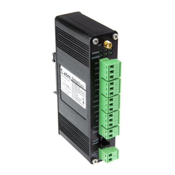
ETM DELTABLACK
INDUSTRIAL CELLULAR REMOTE MONITORING,
ALARMING & LOGGING SOLUTION
For Support Contact +46 8 25 28 75, sales@etmiot.se or +61 2 9956 7377, sales@etmiot.com.au
1802-20200009 RevA, 2020-03-04
USER
GUIDE
Features:
•
Integrated 7-channel data logger including
one relay output
•
DIN-rail mounted including wall mount
bracket
•
Integrated 2G/3G/4G wireless modem
•
Customized SMS alerts
•
LED indicators for cellular signal quality
and communication status
•
Pre-configured for the most common
sensor types
•
Easy access to logged measurements via
ETM's IoT Cloud Dashboard (EWO)
•
Easy integration to PLC, SCADA and
telemetry systems
Advertisement
Table of Contents

Summary of Contents for ETM DeltaBlack Series
- Page 1 Customized SMS alerts • LED indicators for cellular signal quality and communication status • Pre-configured for the most common sensor types • Easy access to logged measurements via ETM’s IoT Cloud Dashboard (EWO) • Easy integration to PLC, SCADA and telemetry systems...
-
Page 2: Table Of Contents
Overview..............................5 Physical Dimensions ..........................6 Specifications ............................6 Power Supply ............................7 External Connector – ETM DeltaBlack #71610 ..................8 External Connector – ETM DeltaBlack #71611 ..................9 Serial (RS232) Port ..........................10 Internal Dip Switches ..........................11 Indicator LED’s............................13 Green signal strength LED’s (Top row) .................... - Page 3 For Support Contact +46 8 25 28 75, sales@etmiot.se or +61 2 9956 7377, sales@etmiot.com.au Power in Low Level ..........................24 Analogue Input Alarm ..........................24 Data Transfer / Logging / Timers tab ...................... 25 Common settings for all channels ......................25 Setting the SWT timers ..........................
- Page 4 For Support Contact +46 8 25 28 75, sales@etmiot.se or +61 2 9956 7377, sales@etmiot.com.au Wiring Diagram ............................44 Configuration Tool Settings ........................45 Tank Level monitoring with Rochester Gauge ..................46 Water/Electrical meter measurement ...................... 47 Pressure Sensor ............................48 Control Via ET Commands ........................
-
Page 5: Introduction
SMS commands. The DeltaBlack can be delivered with a pre-provision world wide SIM-card. Connect the sensors, turn on the power and log into ETM's IoT Cloud Dashboard (EWO) to remotely manage DeltaBlack and get access to the measured data from anywhere. -
Page 6: Physical Dimensions
For Support Contact +46 8 25 28 75, sales@etmiot.se or +61 2 9956 7377, sales@etmiot.com.au Physical Dimensions Applications: Typical applications include: • Pump, fan, generator and motor • Refrigeration and freezer systems • Metering, HVAC, indoor climate • Tank measurements •... -
Page 7: Power Supply
For Support Contact +46 8 25 28 75, sales@etmiot.se or +61 2 9956 7377, sales@etmiot.com.au Case Casing DeltaBlack features an aluminium casing made for heavy-duty industrial applications. DIN-rail mount DeltaBlack can be attached to a DIN-rail for easy mounting. Wall mount DeltaBlack can also be mounted on a flat surface using the included bracket (e.g. -
Page 8: External Connector - Etm Deltablack #71610
For Support Contact +46 8 25 28 75, sales@etmiot.se or +61 2 9956 7377, sales@etmiot.com.au External Connector – ETM DeltaBlack #71610 Seven I/O’s including a relay is available through the terminal blocks. Pin allocations are as shown below. The configuration to set the channel function is done in the configuration tool described on page 15 “Configuration tool”. -
Page 9: External Connector - Etm Deltablack #71611
For Support Contact +46 8 25 28 75, sales@etmiot.se or +61 2 9956 7377, sales@etmiot.com.au External Connector – ETM DeltaBlack #71611 Seven I/O’s including a relay is available through the terminal blocks. Pin allocations are as shown below. The configuration to set the channel function is done in the configuration tool described on page 15 “Configuration tool”. -
Page 10: Serial (Rs232) Port
For Support Contact +46 8 25 28 75, sales@etmiot.se or +61 2 9956 7377, sales@etmiot.com.au Serial (RS232) Port The RS232 Port is the primary interface for the configuration tool software. ET/AT commands can also be used to communicate with the terminal. The RS232 interface is implemented as an 8-pin RJ45 socket. -
Page 11: Internal Dip Switches
For Support Contact +46 8 25 28 75, sales@etmiot.se or +61 2 9956 7377, sales@etmiot.com.au Internal Dip Switches SWITCH DESCRIPTION MODULE Not used OFF= Ch 2: DI (default high, dry contact to ground or LL<0.5V, HL>2.5V), AI (0 to 2.5V), Pulse in, DO (0 or 3.3V, 10uA) ON= Ch 2: AI 4-20 mA OFF= Ch 3: DI (default high, dry contact to ground or... - Page 12 For Support Contact +46 8 25 28 75, sales@etmiot.se or +61 2 9956 7377, sales@etmiot.com.au External ports The ETM DeltaBlack terminal features a standard SMA-F antenna connector. Note! If you intend to use the external ports, please see (General settings tab) for setup using the configuration tool.
-
Page 13: Indicator Led's
For Support Contact +46 8 25 28 75, sales@etmiot.se or +61 2 9956 7377, sales@etmiot.com.au Indicator LED’s Green signal strength LED’s (Top row) GREEN LED 1 FUNCTION Flashing RSSI < -105 dBm ≥ RSSI -105 dBm (Poor signal) Not registered to mobile network GREEN LED 2 FUNCTION ≥... - Page 14 For Support Contact +46 8 25 28 75, sales@etmiot.se or +61 2 9956 7377, sales@etmiot.com.au Signal strength levels.
-
Page 15: Configuration Tool
(0702 being the relevant part in the example below), the correct version for the unit is shown in the terminal window. If you do not have the correct version of the configuration tool, contact ETM and request the appropriate version or visit ETM’s website. -
Page 16: Using The Configuration Tool
For Support Contact +46 8 25 28 75, sales@etmiot.se or +61 2 9956 7377, sales@etmiot.com.au Using the Configuration Tool When you power up the wireless modem to do any configuration you MUST follow these steps if you are unfamiliar with the operation of the Configuration Tool: 1. -
Page 17: Saving, Reading And Writing Configuration Files
For Support Contact +46 8 25 28 75, sales@etmiot.se or +61 2 9956 7377, sales@etmiot.com.au Saving, reading and writing configuration files • To open an existing configuration file, select "File – Open". • To save a configuration file, select "File – Save". This can be done after you have read an existing configuration from the wireless modem, or when you have manually entered a configuration. -
Page 18: General Settings Tab
For Support Contact +46 8 25 28 75, sales@etmiot.se or +61 2 9956 7377, sales@etmiot.com.au GENERAL SETTINGS TAB Phone number to SMS Alarm recipients • Number 1-5 lists the recipients of the alarm messages. It is our recommendation that you use the full international number in any entry, e.g. -
Page 19: Miscellaneous
"Use incoming SMS security filter". With this setting, only phone numbers in the phone number list will be accepted. • "Reference Date" – Reference date (typical 05-01-01) is need for the Real Time Clock set by ETM IoT Cloud Dashboard (EWO). -
Page 20: Hw Model No - Hw Serial No
For Support Contact +46 8 25 28 75, sales@etmiot.se or +61 2 9956 7377, sales@etmiot.com.au HW Model No - HW Serial No Here the model number and serial number for the unit are shown. Init AT/ET-Command Table Here you may set various AT and/or ET commands that are executed at power up. Alarm messages •... -
Page 21: Channels Tab
For Support Contact +46 8 25 28 75, sales@etmiot.se or +61 2 9956 7377, sales@etmiot.com.au CHANNELS TAB This section has settings for the I/O channels and the corresponding alarms. For channels 1, we have the following options: Open→Close(N.O) Alarm Message This message will be sent when a circuit involving the actual I/O pin changes from open to closed (from not connected to grounded). -
Page 22: Alarm (Port 2200)
For Support Contact +46 8 25 28 75, sales@etmiot.se or +61 2 9956 7377, sales@etmiot.com.au Alarm (port 2200) • "TCP Server Selection" allows for the sending of any alarm via TCP to server address and port specified in the Communication tab. •... - Page 23 For Support Contact +46 8 25 28 75, sales@etmiot.se or +61 2 9956 7377, sales@etmiot.com.au Allows for high level, low level or both, with hysteresis. Hysteresis can be set; this is useful in eliminating nuisance alarms resulting from analogue values fluctuating above and below the alarm set point, which would otherwise cause multiple alarms to be sent.
-
Page 24: Alarm Message
For Support Contact +46 8 25 28 75, sales@etmiot.se or +61 2 9956 7377, sales@etmiot.com.au Alarm message Set an alarm message for low battery level. Power in Low Level If the supply voltage falls below this value, the unit will turn into shutdown mode. Here, the cellular module will be turned off, and only the processor will be operational. -
Page 25: Data Transfer / Logging / Timers Tab
For Support Contact +46 8 25 28 75, sales@etmiot.se or +61 2 9956 7377, sales@etmiot.com.au DATA TRANSFER / LOGGING / TIMERS TAB Common settings for all channels • "Log interval in min" – Input value in minutes to decide logging •... - Page 26 SWT3 – This time sends the current values as configured. The sending port will be 2800. • SWT4 – This time sends the current values as configured. The sending port will be 2880. The data types are defined in the separate document "ETM Modems TCP UDP Protocol spec". Contact ETM for details.
-
Page 27: Setting The Swt Timers
For Support Contact +46 8 25 28 75, sales@etmiot.se or +61 2 9956 7377, sales@etmiot.com.au Setting the SWT timers Setting the SWT timers is done by entering the interval in minutes in the periodicity area. Select if the unit shall send the data in periodic interval starting at the unit boot up time or if the data send interval shall be synchronised on the hour change e.g. -
Page 28: Channel Selection
• [#8] format, ET-Command response – this allows the server to interrogate the wireless modem. These data types are defined in the separate document "ETM Modems TCP UDP Protocol spec". Contact ETM for details. Monitoring data (SWT4) This will send certain types of data trough port 2880 (see above for description). -
Page 29: What You Should Know About The Low Power Mode
For Support Contact +46 8 25 28 75, sales@etmiot.se or +61 2 9956 7377, sales@etmiot.com.au analogue alarms will function in sleep mode; however the delays before an alarm is sent are affected by the analogue alarm check period and the time for the unit to wake up and register –... -
Page 30: Heart Beat Package
For Support Contact +46 8 25 28 75, sales@etmiot.se or +61 2 9956 7377, sales@etmiot.com.au • During Low Power Mode operation a change on a configured I/O that would normally cause an alert to occur will cause the unit to wake up. The I/O’s are scanned every X minutes in Low Power Mode, so there is no guarantee that a unit will stay in Low Power Mode for as long as expected. - Page 31 For Support Contact +46 8 25 28 75, sales@etmiot.se or +61 2 9956 7377, sales@etmiot.com.au • Ping Sending: o "Ping format" needs to be checked for this feature to function. o "No of Ping failures before ISP disconnect" means that if an initial data send cannot be initiated then a "ping failure"...
-
Page 32: Communication Tab
For Support Contact +46 8 25 28 75, sales@etmiot.se or +61 2 9956 7377, sales@etmiot.com.au COMMUNICATION TAB This section has settings which controls how the wireless modem communicates over the internet with a server. There are also settings for the communication with the internal module. -
Page 33: Connected To Isp Or Server
For Support Contact +46 8 25 28 75, sales@etmiot.se or +61 2 9956 7377, sales@etmiot.com.au • "ISP User Name" and "ISP Password" is the appropriate login information for the service being utilised. Connected to ISP or Server • Connect to ISP at startup – When the unit powers up it can automatically connect to the ISP. •... -
Page 34: Internal Serial - Setting The Baud Rate
For Support Contact +46 8 25 28 75, sales@etmiot.se or +61 2 9956 7377, sales@etmiot.com.au Internal Serial – setting the baud rate The baud rate for the wireless modem can be set in this section. As default the unit is set to a baud rate of 115200. -
Page 35: Logged Data Tab
For Support Contact +46 8 25 28 75, sales@etmiot.se or +61 2 9956 7377, sales@etmiot.com.au LOGGED DATA TAB A limited amount of data can be stored in the memory during periods of network outages or if sleep mode is used. Channel values Latest value for all input channels. -
Page 36: Terminal Tab
For Support Contact +46 8 25 28 75, sales@etmiot.se or +61 2 9956 7377, sales@etmiot.com.au TERMINAL TAB In the terminal window you can see the output from the unit and type commands to the unit. Note: Remember to place the cursor inside the window before you type any commands. Entering command mode Place the cursor inside the window and press "escape"... -
Page 37: Set Rtc
For Support Contact +46 8 25 28 75, sales@etmiot.se or +61 2 9956 7377, sales@etmiot.com.au Set RTC This button is used to set the Reference Date and Time. Reprogram using CSD If your SIM has been provisioned for Circuit Switched Data, then it is possible to dial into the unit from the terminal window and re-program the unit remotely. -
Page 38: Channel Scaling Tab
For Support Contact +46 8 25 28 75, sales@etmiot.se or +61 2 9956 7377, sales@etmiot.com.au CHANNEL SCALING TAB This tab shows the current calibration/scaling parameters for the input. Each analogue channel has the resolution of 4096 steps. Example: We have a temperature sensor, specified to give 1000 mV at 10 °C and 2000 mV at 20 °C. If we are using an analogue channel configured for 0-2500 mV, this corresponds to the steps 0-4095. -
Page 39: Application Examples
For Support Contact +46 8 25 28 75, sales@etmiot.se or +61 2 9956 7377, sales@etmiot.com.au APPLICATION EXAMPLES This section includes a few examples of how the devices can be electronically wired as well as a couple of software configurations for different types of common applications. BASIC I/O CONTROL Wiring Diagram... -
Page 40: Configuration Tool Settings
For Support Contact +46 8 25 28 75, sales@etmiot.se or +61 2 9956 7377, sales@etmiot.com.au Configuration Tool Settings 1. Enter Phone Numbers and Unit ID in the General Settings tab. In Data Transfer/Logging/Times, Set "Data Logging" to "On(Timed/Event on I/O1)" and "both"... -
Page 41: Temperature Alarm
For Support Contact +46 8 25 28 75, sales@etmiot.se or +61 2 9956 7377, sales@etmiot.com.au TEMPERATURE ALARM Wiring Diagram... -
Page 42: Configuration Tool Settings
2500mV. Therefore the 1500mV trip point equates to 22.5 °C, in the example below a restore message will be sent when the temperature drops back below 22.5 °C. Note: contact ETM for more information on how to correctly set and calibrate analogue inputs. -
Page 43: Pump Control
For Support Contact +46 8 25 28 75, sales@etmiot.se or +61 2 9956 7377, sales@etmiot.com.au PUMP CONTROL... -
Page 44: Tank Level Monitoring With 4-20Ma Sensor
For Support Contact +46 8 25 28 75, sales@etmiot.se or +61 2 9956 7377, sales@etmiot.com.au TANK LEVEL MONITORING WITH 4-20mA SENSOR Wiring Diagram... -
Page 45: Configuration Tool Settings
2. In Data Transfer/Logging/Times, Set "Data Logging" to "On(Timed)" and check the box "Toggle SensFeed(ch30)". Check "Input Ch 3 (I/O3)" and make sure that it's set to Analogue. Note: Contact ETM for more information on how to correctly set and calibrate analogue inputs. -
Page 46: Tank Level Monitoring With Rochester Gauge
For Support Contact +46 8 25 28 75, sales@etmiot.se or +61 2 9956 7377, sales@etmiot.com.au TANK LEVEL MONITORING WITH ROCHESTER GAUGE... -
Page 47: Water/Electrical Meter Measurement
For Support Contact +46 8 25 28 75, sales@etmiot.se or +61 2 9956 7377, sales@etmiot.com.au WATER/ELECTRICAL METER MEASUREMENT... -
Page 48: Pressure Sensor
For Support Contact +46 8 25 28 75, sales@etmiot.se or +61 2 9956 7377, sales@etmiot.com.au PRESSURE SENSOR... -
Page 49: Control Via Et Commands
For Support Contact +46 8 25 28 75, sales@etmiot.se or +61 2 9956 7377, sales@etmiot.com.au CONTROL VIA ET COMMANDS As default the DeltaBlack is set to ET Command Mode. ET Commands are specific to ETM terminals and allow for control, configuration and information requests to be sent to and from the terminal. -
Page 50: I/O Commands
For Support Contact +46 8 25 28 75, sales@etmiot.se or +61 2 9956 7377, sales@etmiot.com.au ETSC1 Change to AT-command mode ETSPW=xxxxxxx Set a password for the configuration tool Use up to 7 characters. The unit will be ready for configuration. It is locked ETPW=xxxxxxx Enter the password again after 10 minutes, and at reset. -
Page 51: Pulse Input Commands
For Support Contact +46 8 25 28 75, sales@etmiot.se or +61 2 9956 7377, sales@etmiot.com.au COMMAND ACTION RESPONSE/NOTES All numbers must be entered, if less than 5 numbers enter ,’s with no spaces between until all 5 slots are completed e.g. ET-SSP=XXXXXXXXXX,,,, Note: you cannot add/or remove phone numbers to ET-SSP=PhNo1,... -
Page 52: Other Commands
For Support Contact +46 8 25 28 75, sales@etmiot.se or +61 2 9956 7377, sales@etmiot.com.au ET-IS? Get the current Socket status ET-ISO or Perform an ActiveOpen and establish a Socket Connect to an ISP if not connected. ET-ISO=IP1 ET-I&IP Get network connection status profile ET-IAPN1 Set APN ET-I&LIP... - Page 53 For Support Contact +46 8 25 28 75, sales@etmiot.se or +61 2 9956 7377, sales@etmiot.com.au ETM Mätteknik AB ETM Pacific Pty Ltd Ekbacksvägen 32, SE-168 69 Bromma, Sweden Suite 6, 273 Alfred Street, North Sydney NSW 2060, Australia Tel: +46 (0)8 25 28 75 Fax: +46 (0)8 80 11 10...
Need help?
Do you have a question about the DeltaBlack Series and is the answer not in the manual?
Questions and answers