Table of Contents
Advertisement
Quick Links
Advertisement
Table of Contents

Related Manuals for Hoymiles HM-1000N


Summary of Contents for Hoymiles HM-1000N
- Page 1 Version 1.2 (June 2020)
- Page 2 About the Manual This manual contains important instructions for the HM-1000N/HM-1200N/HM-1500N Microinverter and must be read in its entirety before installing or commissioning the equipment. For safety, only qualified technician, who has received training or has demonstrated skills can install and maintain this Microinverter under the guide of this document.
-
Page 3: Table Of Contents
6.4 Routine Maintenance ..........................20 6.5 Replace Microinverter ..........................20 7. Decommissions ..............................21 7.1 Decommissions ............................21 7.2 Storage and Transportation ........................22 7.3 Disposal ..............................22 8. Technical Data ..............................22 © 2019 Hoymiles Converter Technology Co., Ltd. All rights reserved. - Page 4 Appendix 1: ................................27 Installation Map ..............................27 Appendix 2: ................................28 WIRING DIAGRAM –120VAC / 240VAC SPLIT PHASE: ................28 WIRING DIAGRAM – 120VAC / 208VAC THREE PHASE: ............... 29 © 2019 Hoymiles Converter Technology Co., Ltd. All rights reserved.
-
Page 5: Important Notes
2. About Safety 2.1 Important Safety Instructions The HM-1000N/HM-1200N/HM-1500N Microinverter is designed and tested according to international safety requirements. However, certain safety precautions must be taken when installing and operating this inverter. The installer must read and follow all instructions, cautions and warnings in this installation manual. -
Page 6: Explanation Of Symbols
Ø Do not use the equipment if any operating anomalies are found. Avoid temporary repairs. Ø All repairs should be carried out using only qualified spare parts, which must be installed in accordance with their intended use and by a licensed contractor or authorized Hoymiles service representative. -
Page 7: Radio Interference Statement
“The world’s First Daisy-Chain 4 in 1 Unit Microinverter” with extremely wide DC input operating voltage range (16-60V) and low start-up voltage (22V only). Hoymiles 4 in 1 unit Microinverter HM-1000N/HM-1200N/HM-1500N is the perfect selection for PV © 2019 Hoymiles Converter Technology Co., Ltd. All rights reserved. -
Page 8: Highlights
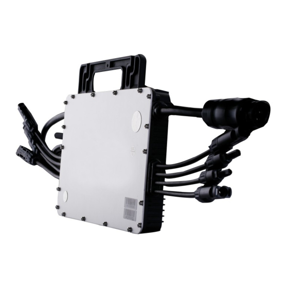
External antenna for stronger communication with DTU. High reliability: NEMA6 (IP67) enclosure; 6000V surge protection. 3.3 Terminals Introduction Object Description AC Connector (male) AC Connector (Female) DC Connectors 3.4 Dimension(mm) © 2019 Hoymiles Converter Technology Co., Ltd. All rights reserved. -
Page 9: About Function
*Note: All accessories above are not included in the package, and need to be purchased separately. Please contact our sales representative for the price. (M8 screws need to be prepared by installer-self.) © 2019 Hoymiles Converter Technology Co., Ltd. All rights reserved. -
Page 10: Installation Precaution
Under such installation conditions, it is better for the microinverters to be installed 50cm above the roof. Otherwise, more DTUs may be required to ensure the communication quality between the DTUs and the microinverters. © 2019 Hoymiles Converter Technology Co., Ltd. All rights reserved. -
Page 11: Preparation
Install Microinverter underneath of the photovoltaic modules to make sure it works in theshadow. If this condition cannot be met, might trigger the inverter production de-rating. Fig.1 Installation position of microinverter © 2019 Hoymiles Converter Technology Co., Ltd. All rights reserved. -
Page 12: Installation Steps
1.2m please use the AC extension cable between two inverters (As picture indicated below). B) Install the AC end cap on the open AC connector of the last microinverter in the AC branch circuit. © 2019 Hoymiles Converter Technology Co., Ltd. All rights reserved. - Page 13 C) Connect the other side of the AC end cable to the distribution box, and wire it to the local grid network. Step 4. Create an Installation Map A) Peel the removable serial number lable from each microinverter (The position of the label is shown as below.) © 2019 Hoymiles Converter Technology Co., Ltd. All rights reserved.
- Page 14 B) Affix the serial number label to the respective location on the installation map. Step 5. Connect PV Modules Mount the PV modules above the microinverter. B) Connect the PV modules’ DC cables to the DC input side of the microinverter. © 2019 Hoymiles Converter Technology Co., Ltd. All rights reserved.
-
Page 15: Troubleshooting
Hoymiles technical support. 1.Check if the grid configuration parameter is correct and upgrade again. Grid configuration 2. If the fault still exists, contact your dealer or Hoymiles technical parameter error support. 1. If the alarm occurs accidentally and the microinverter can still work Software error code normally, no special treatment is required. - Page 16 2. If the alarm occurs frequently, check whether the grid voltage is within the acceptable range. If no, contact the local power operator or change the grid overvoltage protection limit via Hoymiles monitoring system with the consent of the local power operator.
- Page 17 2. If the alarm occurs frequently, check whether the grid frequency change rate is within the acceptable range. If no, contact the local power operator or change the grid frequency change rate limit via Hoymiles monitoring system with the consent of the local power operator.
-
Page 18: Status Led Indicator
2. If the alarm occurs frequently and cannot be recovered, contact your dealer or Hoymiles technical support. 6.2 Status LED Indicator The LED flashes five times at start up. All green flashes (1s gap) indicate normal start up. © 2019 Hoymiles Converter Technology Co., Ltd. All rights reserved. -
Page 19: On-Site Inspection (For Qualified Installer Only)
ü Flashing Red and Green alternately: Firmware is corrupted. *Note: All the faults are reported to the DTU, refer to the local APP of the DTU or Hoymiles Monitoring Platform for more information. 6.3 On-site Inspection (For qualified installer only) To troubleshoot an inoperable microinverter, follow the steps in the order shown. -
Page 20: Routine Maintenance
Remove the PV panel from the racking, and cover the panel. Using a meter to measure and make sure there is no current flowing in the DC wires between Ø © 2019 Hoymiles Converter Technology Co., Ltd. All rights reserved. -
Page 21: Decommissions
Please pack the Microinverter with the original packaging, or use the carton box that can afford 5kg weight and can be fully closed if the original packaging is no longer available. © 2019 Hoymiles Converter Technology Co., Ltd. All rights reserved. -
Page 22: Storage And Transportation
HM-1000N/HM-1200N/HM-1500N 7.2 Storage and Transportation Hoymiles packages and protects individual components using suitable means to make the transport and subsequent handling easier. Transportation of the equipment, especially by road, must be carried out by suitable ways for protecting the components (in particular, the electronic components) from violent, shocks, humidity, vibration, etc. -
Page 23: Dc Input
Model HM-1000N HM-1200N HM-1500N Peak inverter efficiency 96.70% 96.70% 96.70% CEC weighted efficiency 96.50% 96.50% 96.50% Nominal MPPT efficiency 99.80% 99.80% 99.80% Night time power consumption (mW) <50 <50 <50 © 2019 Hoymiles Converter Technology Co., Ltd. All rights reserved. -
Page 24: Mechanical Data
The HM-1000N/HM-1200N/HM-1500N Microinverter is a grid support interactive inverter, which is also known as a Grid Support Utility Interactive Inverter. And these microinverters also comply with California Rule 21. The Grid Support Support functions are controlled on Hoymiles Monitoring Platform and the DTU is required in this PV system. - Page 25 < 57.0 Not Applicable 0.16 sec. 0.16 sec. 2 (LF2) Through SA11: Ramp Rate (RR) and Soft Start (SS) Adjustment Range Units Tolerance Ramp up rate %Irated/s +/- 4% © 2019 Hoymiles Converter Technology Co., Ltd. All rights reserved.
- Page 26 SA15: Volt-Watt (VW) Units HM-1000 HM-1200 HM-1500 Output power rating 1200 1438 Output Power accuracy %Prated Maximum Slope of active power reduction %Prated/Hz Minimum Slope of active power reduction %Prated/Hz © 2019 Hoymiles Converter Technology Co., Ltd. All rights reserved.
-
Page 27: Installation Map
HM-1000N/HM-1200N/HM-1500N Appendix 1: Installation Map © 2019 Hoymiles Converter Technology Co., Ltd. All rights reserved. -
Page 28: Wiring Diagram -120Vac / 240Vac Split Phase
HM-1000N/HM-1200N/HM-1500N Appendix 2: WIRING DIAGRAM –120VAC / 240VAC SPLIT PHASE: © 2019 Hoymiles Converter Technology Co., Ltd. All rights reserved. -
Page 29: Wiring Diagram - 120Vac / 208Vac Three Phase
HM-1000N/HM-1200N/HM-1500N WIRING DIAGRAM – 120VAC / 208VAC THREE PHASE: © 2019 Hoymiles Converter Technology Co., Ltd. All rights reserved.
Need help?
Do you have a question about the HM-1000N and is the answer not in the manual?
Questions and answers