Table of Contents
Advertisement
Quick Links
Advertisement
Table of Contents

Subscribe to Our Youtube Channel
Summary of Contents for GSS GSS.standard STC 816
- Page 1 STC 816...
-
Page 2: Table Of Contents
o n t e n t s 1 Notes about safety and hazards ..............4 2 General information ..................6 Meaning of the symbols used ............6 Scope of delivery ................6 Available accessories ..............6 Technical data ................7 Description ...................8 3 Overview ....................9 Front cover ...................9 Connectors and components ............10 Front view / side view (type label) ............10 View from below .................11 Rear view ...................12... - Page 3 9 The control panel at a glance ..............22 Control panel ................22 Menu items .................22 10 Updating the software of the control unit ............ 23 10.1 Updating software via PC .............23 10.2 Updating the software via second control unit .........23 Removing master control unit ............23 Programming slave control unit ............24 Inserting master control unit ............25 11 Programming ....................
-
Page 4: Notes About Safety And Hazards
otes a bo u t sa fe t y a n d h a z a r ds • Observe the relevant VDE regulations. • If the power cord needs to be replaced, only use an OEM power cord (EMC). • The standards EN/DIN EN 50083 resp. IEC/EN/DIN EN 60728 must be observed, especially concerning equipotential bonding and earthing. •... - Page 5 • Do not place any vessels containing liquids on the head-end station. • Do not place anything on the head-end station which could initiate fires (e.g. candles). • Due to the risk of fires caused by lightning strikes, we recommend that all mechanical parts (e.g.
-
Page 6: General Information
e n e r a l i n fo r m ati o n 2.1 m e a n i n G t h e s ym b o l s u s e d Important note • Performing works Danger by electrical shock —>... -
Page 7: Technical Data
2.4 t e C h n i C a l data The devices meet the following EU directives: 2011/65/EU, 2014/30/EU, 2014/35/EU The product fulfils the guidelines and standards for CE labelling (page 37). Unless otherwise noted all values are specified as "typical". General Cassette slots: ..................8 Admissible ambient temperature: .........0 °C … +50 °C... -
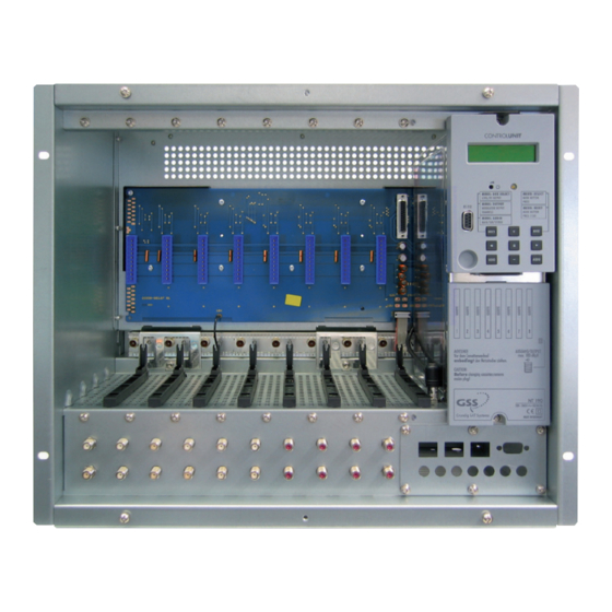
Page 8: Description
Decoupling loss of the inputs: ............30 dB Gain: ...................13 dB Output level with 16 channels ........maximum 100 dBµV Power supply NT 190 Mains voltage: ............ 220–240V~, 50/60 Hz Power consumption (fully equipped, incl. LNB power supply): ..150 W 2.5 d es C r i p t i o n The head-end station has a modular structure and can hold up to 8 Standard cassettes. -
Page 9: Overview
When the head-end station is shipped from the factory, the default setting for the RF output level of the output collector is -3 dB. You can use the software of the control unit to program the master output level of the head-end station. The software version of the control unit appears on the two-line LC display after switching on the head-end station. -
Page 10: Connectors And Components
3.2 C o n n e C to rs a n d C o m p o n e n t s ro n t v i e w s i d e v i e w t y p e l a b e l Fig. -
Page 11: View From Below
i e w f r o m b e low Fig. 3 SAT IF input distributors Inputs of the SAT IF input distributors SAT IF loop-through outputs RF output of the head-end station Fig. 4 Mains connector Distributor for LNB operating voltage Openings for the strain relief of the mains connection cable Openings for the potential equalisation screw - 11 -... -
Page 12: Rear View
e a r v i e w & & Fig. 5 Openings for the strain relief of the mains connection cable Opening for the securing screw Openings for mounting screws (wall mounting) & 3.3 C o n t r o l u n i t £... -
Page 13: Installing The Head-End Station
ns ta l l i n G th e h e a d e n d s tati o n 4.1 emC r e G u l at i o n s e l e c t rom ag n e t i c Co m pat i b i l i t y To comply with the current EMC regulations, it is necessary to connect the lines leading in and out of the head-end station (e.g. Cinch, RF) using standard ca- ble terminals. -
Page 14: Remove
4.2 r e m ov e f r o n t C ov e r Fig. 7 • Unscrew the locking screws • Loosen the mounting screws • Slide the front cover upwards and unhook it. 4.3 m o u n t i n G t h e h e a d e n d... -
Page 15: Wall Mounting
a l l m o u n t i n G —> Use mounting material suitable for the wall properties. —> Position the head-end station so that the distance of free space be- low and above is minimum 50 cm. —> The distance of the upper holes is 413 mm. 413 mm 30 mm 30 mm... -
Page 16: Mounting In A 19" Cabinet
19" o u n t i n G C a b i n e t The head-end station has been designed for installation into 19“ rack systems. —> The total installation height of a 19“ unit is 9 HU (39.7 cm, hole spacing 26.5 cm). -
Page 17: Installing A Cassette
n s t a l l i n G C a s s e t t e Before installing or changing a cassette unplug the power cable of the head- end station from the mains power socket. Fig. 10 • Remove the fastening screws of an unoccupied slot from the bracket of the head-end station. -
Page 18: Power Supply
o w e r s u p p l y 6.1 sat if i n p u t d i s t r i b u to r See figures 11 and 12 for the power supply for the SAT IF input distributors. The power distributor (fig. -
Page 19: Connecting The Head-End Station
o n n e C t i n G t h e h e a d e n d s t a t i o n 7.1 (pe) ot e n t i a l e q ua l i sat i o n Equalise the potential (PE) in accordance with IEC/EN/DIN EN 60728. -
Page 20: Connecting Sat If Inputs
sat if o n n e C t i n G i n p u t s The following description refers to one of the SAT IF input distributors. The other SAT IF input distributors are connected in the same manner. •... -
Page 21: Mains Connection
7.4 m a i n s C o n n e C t i o n • Mount the power cord + strain relief (Fig. 16a) optionally at the rear/bot- tom side (Abb. 16b). Connect the power cord to the PSU (Abb. -
Page 22: Setting The Contrast Of The Display
e t t i n G t h e C o n t r a s t t h e d i s p l a y • Adjust the contrast of the display using the controller £ ¡ ™ C o n t r o l p a n e l G l a n C e... -
Page 23: Updating The Software Of The Control Unit
10 u p d a t i n G t h e s o f t w a r e t h e C o n t r o l u n i t 10.1 u p dat i n G s o f t wa r e v i a The RS 232 interface of the control unit enables you to use a PC or a notebook... -
Page 24: Programming Slave Control Unit
r o G r a m m i n G s l av e C o n t r o l u n i t • Switch off the head-end station of the slave control unit. • Connect the 15-pin D-SUB plug on the back of the master control unit to the RS 232 interface of the head-end station’s slave control unit via a connec- tion cable made on-site as follows. -
Page 25: Inserting Master Control Unit
n s e r t i n G m a s t e r C o n t r o l u n i t § • Connect control unit to the snap-in hook § • Push the control unit towards the head-end station, in the direction opposite that of arrow "... -
Page 26: Programming Procedure
11.2 p ro G r a m m i n G pro C e d u r e Ein / On BE–Remote V 45 please wait … t > 10 s t > 10 s Box … – – – Page 27 –... -
Page 27: Message After Temperature Exceeding
STATION NUMBER: SYSTEM MODEM: ON / OFF Page 26 SYSTEM SECURE: ◀ ▶ PASSWORD 0000 es saG e a f t e r t e m p e r at u r e e xC e e d i n G Instead of the standby "BE-Remote"... -
Page 28: Programming The Head-End Station
11.3 p r o G r a m m i n G t h e h e a d e n d s tat i o n —> Pressing the button for longer than 2 seconds cancels the programming procedure. This takes you back to the program item "Activating system information"... -
Page 29: Activating System Information
C t i vat i n G s ys t e m i n f o r m at i o n Box … – – – – – – – – – • Activate the "System information" software by simultaneously holding down the buttons for more than 2 seconds in the "Selecting the cas- sette"... -
Page 30: System Information - Output Collector
– ys t e m i n f o r m at i o n o u t p u t C o l l e C to r This menu shows the software version of the output collector (e.g. "V 1"). SYSTEM INFO: Output-Coll. -
Page 31: System Information - Number Of The Head-End Station
– ys t e m i n f o r m at i o n n u m b e r t h e h e a d e n d s tat i o n This menu shows the number of the head-end station (see also item "Setting the consecutive number of the head-end station", page 32). -
Page 32: Setting The Rf Output Level Of The Head-End Station
and equal their RF output levels to the value of the cassette with the lowest RF output level using the buttons ("0 … -25 dB") • Press the button. —> The "Setting the RF output level of the head-end station" – "STATION LEVEL:" menu is activated. rf e t t i n G t h e... -
Page 33: Setting The Password
C t i vat i n G t h e m o d e m C o n n e C t i o n If the head-end station is to be remote controlled using the PSW 1000 configu- ration software and a modem connected to the head-end station (without HRCU 8 / RCU 1) activate the modem mode in this menu ("ON"). -
Page 34: Saving Settings
av i n G s e t t i n Gs • Press the button. —> The settings are saved. —> You return to the "Activating system information" menu item (page 29). —> By pressing the button, you will be returned to the menu item "System information –... -
Page 35: System Information
ys t e m i n f o r m at i o n In this menu, the inner temperature is displayed which activated the lock (e.g. "68 °C") and the highest inner temperature recorded to date (e.g. "84 °C"). The inner temperature which activated the lock must be deleted to reactivate the temperature monitor and the software. -
Page 36: Final Procedures
12 f i n a l pro C e d u res After installing the head-end station, upgrading accessories or installing cas- settes it is necessary to tighten all cable connections, cable terminals and cover screws in order to maintain compliance with current EMC regulations securely. • Securely tighten the cable connections (Cinch, RF connectors) using an ap- propriate open-ended spanner. • Hang the front cover into the mounting screws • Tighten the mounting screws. •... - Page 37 Phone: +49 (0) 911 / 703 8877 • Fax: +49 (0) 911 / 703 9210 www.gss.de/en • info@gss.de CLASS CLASS Service: Phone: +49 (0) 911/703 2221; Fax: +49 (0) 911/703 2326; service@gss.de Alterations reserved. Technical data E. & O.E. © by GSS Grundig Systems GmbH V45/001/2017...
Need help?
Do you have a question about the GSS.standard STC 816 and is the answer not in the manual?
Questions and answers