Table of Contents
Advertisement
Advertisement
Table of Contents

Related Manuals for OHAUS Guardian 5000 Series


Summary of Contents for OHAUS Guardian 5000 Series
- Page 1 OHAUS Guardian 5000 Series Hotplate-Stirrer, e-G51 HSRDM Hotplate-Stirrer, e-G51 HS07C Hotplate, e-G51 HP07C Stirrer, e-G51 ST07C Hotplate-Stirrer, e-G51 HS1 0C Instruction Manual Test Equipment Depot - 800.517.8431 - 99 Washington Street Melrose, MA 02176 - TestEquipmentDepot.com...
-
Page 3: Table Of Contents
Guardian 5000 Series EN-1 Table of Contents INTRODUCTION ..............................2 1.1. Safety Information ............................2 1.2. Intended Use ............................. 2 1.3. Package Contents ............................. 3 1.4. Installation ..............................3 1.5. Overview ..............................4 1.5.1 Dimensions ............................4 1.5.2 Device Setup ............................9 1.5.3... -
Page 4: Introduction
1. INTRODUCTION This manual contains installation, operation and maintenance instructions for the Ohaus Guardian 5000 Series. Please read the manual completely before using. 1.1. Safety Information Safety notes are marked with signal words and warning symbols. These show safety issues and warnings. Ignoring... -
Page 5: Package Contents
1.4. Installation Upon receiving the Ohaus Hotplate-Stirrer / Hotplate / Stirrer check to ensure that no damage has occurred during shipment. It is important that any damage that occurred in transport is detected at the time of unpacking. If you do find such damage, the carrier must be notified immediately. -
Page 6: Overview
EN-4 Guardian 5000 Series 1.5. Overview 1.5.1 Dimensions Round Top Hotplate-Stirrer 26.7 x 17.3 x 12.7 cm Overall dimensions (L x W x H) (10.5 x 6.8 x 5”) Top plate dimensions: Ø 13.5 cm (5.3”) Top plate material: Aluminum 120 volts ±10%: 8.3 amps... - Page 7 Guardian 5000 Series EN-5 7×7 Hotplate-Stirrer 30.7 x 22.4 x 12.2 cm Overall dimensions (L x W x H) (12.1 x 8.8 x 4.8”) Top plate dimensions: 17.8 x 17.8 cm (7 x 7”) Top plate material: Ceramic 120 volts ±10%: 10.0 amps Electrical (50/60 Hz): 230 volts ±10%: 6.0 amps...
- Page 8 EN-6 Guardian 5000 Series 7x7 Hotplate 30.7 x 22.4 x 12.2 cm Overall dimensions (L x W x H) (12.1 x 8.8 x 4.8”) Top plate dimensions: 17.8 x 17.8 cm (7 x 7”) Top plate material: Ceramic 120 volts ±10%: 10.0 amps Electrical (50/60 Hz): 230 volts ±10%: 6.0 amps...
- Page 9 Guardian 5000 Series EN-7 7x7 Stirrer 30.7 x 22.4 x 12.2 cm Overall dimensions (L x W x H) (12.1 x 8.8 x 4.8”) Top plate dimensions: 17.8 x 17.8 cm (7 x 7”) Top plate material: Ceramic 120 volts ±10%: 1.0 amps Electrical (50/60 Hz): 230 volts ±10%: 0.5 amps...
- Page 10 EN-8 Guardian 5000 Series 10X10 Hotplate-Stirrer 42.2 x 28.6 x 12.2 cm Overall dimensions (L x W x H) (16.6 x 11.25 x 4.8”) Top plate dimensions: 25.4 x 25.4 cm (10 x 10”) Top plate material: Ceramic 120 volts ±10%: 11.2 amps Electrical (50/60 Hz): 230 volts ±10%: 7.0 amps...
-
Page 11: Device Setup
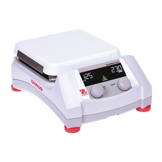
Guardian 5000 Series EN-9 1.5.2 Device Setup Hotplate-Stirrer (Round Top, 7x7, 10x10-230V) A. Display Screen F. Fuse B. Standby Indicator G. Power Entry Module (PEM) C. Left Knob: Controls temperature and settings H. Threaded Knob for Accessory Rod menu I. Standby Switch D. - Page 12 EN-10 Guardian 5000 Series Hotplate-Stirrer (10x10-120V) A. Display Screen G. Power Cord B. Standby Indicator H. Threaded Knob for Accessory Rod C. Left Knob: Controls temperature and settings menu I. Standby Switch D. Right Knob: Controls speed J. Feet: Not adjustable...
- Page 13 Guardian 5000 Series EN-11 Hotplate (7x7) A. Display Screen G. Power Entry Module (PEM) B. Standby Indicator H. Threaded Knob for Accessory Rod C. Knob: Controls temperature and settings menu I. Standby Switch E. External RTD Probe Port J. Feet: Not adjustable...
- Page 14 EN-12 Guardian 5000 Series Stirrer (7x7) A. Display Screen G. Power Entry Module (PEM) B. Standby Indicator H. Threaded Knob for Accessory Rod D. Knob: Controls speed I. Standby Switch F. Fuse J. Feet: Not adjustable Test Equipment Depot - 800.517.8431 - 99 Washington Street Melrose, MA 02176 - TestEquipmentDepot.com...
-
Page 15: Display (Hotplate-Stirrers)
Guardian 5000 Series EN-13 1.5.3 Display (Hotplate-Stirrers) L. Heater Temperature: Switches to external probe temperature when the probe is plugged in and P is illuminated. M. Heater Indicator: Illuminates when heater is running. N. Heat Setting Indicator: Switches Heater Temperature (L) to Heat Setting when illuminated. -
Page 16: Display (Hotplate)
EN-14 Guardian 5000 Series 1.5.4 Display (Hotplate) L. Heater Temperature: Switches to external probe temperature when the probe is plugged in and P is illuminated. M. Heater Indicator: Illuminates when heater is running. N. Heat Setting Indicator: Switches Heater Temperature (L) to Heat Setting when illuminated. -
Page 17: Display (Stirrer)
Guardian 5000 Series EN-15 1.5.5 Display (Stirrer) R. Speed Setting Indicator: Illuminates until stirrer reaches the Speed Setting (S). S. Speed Setting T. Stirrer Indicator: Illuminates when stirrer is running... -
Page 18: Operation
EN-16 Guardian 5000 Series 2 OPERATION 2.1 Getting Ready To get ready: Plug the female end of the provided power cord into PEM (G) on the rear side of the unit. Note: For the 10x10-120V unit, this end of the power cord is fixed to the rear side of the unit. -
Page 19: Controlling The Stirrer
Guardian 5000 Series EN-17 2.3 Controlling the Stirrer 1. Rotate the right knob (D) to control the speed setting (S). Clockwise rotation will increase the speed setting (S). Counterclockwise rotation will decrease the speed setting (S). 2. To turn on the stirrer, press and hold the right knob (D) until the unit beeps and the stirrer indicator (T) illuminates. -
Page 20: Controlling The Top Plate Heater
EN-18 Guardian 5000 Series 2.4 Controlling the Top Plate Heater 1. Rotate the left knob (C) to control the heat setting (L). Clockwise rotation will increase the heat setting (L). Counterclockwise rotation will decrease the heat setting (L). 2. To turn on the heater, press and hold the left knob (C) until the unit beeps and the heater indicator (M) illuminates. - Page 21 The vessel contents being heated may be at a lower temperature depending on the size and thermal conductivity of the vessel. It may be beneficial to monitor the temperature of the vessel contents and adjust the setpoint temperature accordingly. If you need precise control, use the Ohaus External Temperature Probe. Typical Time to Boil Water The chart below is an example of an approximate time to boil for the specified amount of water in a specific vessel.
-
Page 22: Using The External Probe
100°C (boiling). A temperature setpoint greater than 100°C will cause an E7 error. 3. If the Ohaus External Temperature Probe is inserted into the external RTD probe port (E) while the heater is running: The heater will shut off. -
Page 23: The Settings Menu
Guardian 5000 Series EN-21 2.6 The Settings Menu 2.6.1 Accessing / Exiting The settings menu and the following features are only accessible in Hotplate and Hotplate-Stirrer units. 1. To access the settings menu, press and hold the left knob (C) until ‘MENU’ appears on the screen. -
Page 24: Structure & Defaults
EN-22 Guardian 5000 Series 2.6.3 Structure & Defaults Factory Defaults 7x7 & 10x10 0-500°C 0-380°C Pt1 - Pt6 (if saved) SAVE BACK RJCT Pt1 - Pt6 (if saved) BACK BACK BEEP PWRR RSET BACK EXIT... -
Page 25: Using The Single Point Calibration Feature
Guardian 5000 Series EN-23 2.7 Using the Single Point Calibration Feature Single Point Calibration (SPC) improves the accuracy of the heater at user-selected temperature points. Up to 3 points (Plate) and 3 points (Probe) can be stored at once. 1. To control the Single Point Calibration Feature, the unit must first be in the top level of the settings menu. - Page 26 EN-24 Guardian 5000 Series 8. Once the unit has reached the calibration temperature, the SPC icon (O) and the heat setting will blink. 9. With a secondary temperature measurement device, measure the temperature of the top plate or the heated sample at the location of the external probe (if using probe control).
- Page 27 Guardian 5000 Series EN-25 18. Press and hold the left knob (C) until the unit beeps to begin SPC at that temperature. If the probe is connected, the unit will not run plate SPC points. Likewise, if the probe disconnected, the unit will not run probe SPC points.
- Page 28 EN-26 Guardian 5000 Series 26. Briefly press the left knob (C) to confirm selection and return to the Calibration settings menu. 27. To heat to a calibrated temperature, return to the main operating screen. 28. Rotate the left knob (C) to scroll the heat setting (L) to the desired calibrated temperature.
-
Page 29: Enabling / Disabling The Beeper
Guardian 5000 Series EN-27 2.8 Enabling / Disabling the Beeper Disabling the Beeper Setting will prevent beeps in the following scenarios: • Starting and Stopping the Heater • Starting and Stopping the Stirrer • When the heater reaches the set temperature •... -
Page 30: Changing The Power Recovery Setting
EN-28 Guardian 5000 Series 9. Rotate the left knob (C) to scroll to the ‘EXIT’ icon. 10. Briefly press the left knob (C) to return to the main operating screen. Note: There is not an icon to indicate that the beeper has been disabled. -
Page 31: Reset To Factory Default Settings
Guardian 5000 Series EN-29 8. Rotate the left knob (C) to the “BACK” icon. 9. Briefly press the left knob (C) to return to the top level of the settings menu. 10. Rotate the left knob (C) to scroll to ‘EXIT’. - Page 32 EN-30 Guardian 5000 Series 5. Briefly press the left knob (C) to change the Reset settings. The current Reset setting will begin to blink. 6. Rotate the left knob (C) to scroll to the desired Reset setting. 7. Press and hold the left knob (C) until the unit beeps to confirm the Reset setting.
-
Page 33: Maintenance
Always ensure the power is disconnected from the unit prior to any cleaning. If the unit ever requires service, contact your Ohaus representative. The user is responsible for carrying out appropriate decontamination if hazardous material is spilled onto or into the equipment... -
Page 34: Service Information
For service assistance or technical support in the United States call toll-free 1-800-672-7722 ext. 7852 between 8:00 AM and 5:00 PM EST. An OHAUS product service specialist will be available to provide assistance. Outside the USA, please visit our website, www.ohaus.com to locate the Ohaus office nearest you. -
Page 35: Compliance
Operation of this equipment in a residential area is likely to cause harmful interference in which case the user will be required to correct the interference at his own expense. Changes or modifications not expressly approved by Ohaus Corporation could void the user’s authority to operate the equipment. - Page 36 OHAUS products are warranted against defects in materials and workmanship from the date of delivery through the duration of the warranty period. During the warranty period OHAUS will repair, or, at its option, replace any component(s) that proves to be defective at no charge, provided that the product is returned, freight prepaid, to OHAUS.
Need help?
Do you have a question about the Guardian 5000 Series and is the answer not in the manual?
Questions and answers