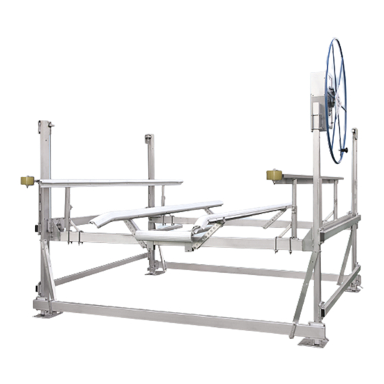
Summary of Contents for RGC VL Series
- Page 1 VL GUIDE ON & BOW STOP INSTRUCTIONS (Applies to P/Ns 3682202, 3682210, 3610250, 3610251, 3610252) REIMANN & GEORGER CORPORATION MARINE PRODUCTS BUFFALO, NY P/N 6112087 04/07/18...
-
Page 2: Table Of Contents
Guide On Support Tube Assembly ....................4 Wood Guide On Assembly ......................5 Bow Stop Tube Arm Assembly ...................... 5 Bow Stop Cross Tube and Bumper Assembly ................6 Bow Stop and Guide On Adjustments .................... 7 RGC MARINE PRODUCTS PHONE: (716) 895-1156... -
Page 3: Safety
MANUAL AND YOUR VERTICAL LIFT MANUAL. FAILURE TO DO THIS CAN LEAD TO EQUIPMENT MISUSE WITH RESULTING DAMAGE AND/OR SERIOUS PERSONAL INJURY. CONTACT YOUR RGC MARINE DEALER IF YOU HAVE ANY QUESTIONS. Do not install this kit without first replacing any damaged or defective parts. - Page 4 Before allowing anyone to operate the lift, be sure they fully understand the proper operating procedure. Do not operate the lift under the influence of drugs, alcohol, or medication. 10. Keep people and pets clear during operation of the lift. 11.
-
Page 5: Installation And Setup
2 INSTALLATION AND SET UP 2.1 PRE-INSTALLATION CHECKS Do not assemble this kit or any other component of the lift if any part appears to be damaged. Do not weld or other wise modify any portion of the lift. Such alterations may weaken the structural integrity of the lift and void the warranty. -
Page 6: Vl Wood Guide On Assembly
Figure 2-1. Guide On Support Tube installation 2.4 WOOD GUIDE ON ASSEMBLY (Refer to Figure 2-2) Position a Bow Stop Guide On (4), on top of the Upper Tube assembly so that the aluminum channel (pre-assembled to wood) rests on top of both Upper Tube mounting plates (2). Insert two spring nuts (F), into the channel as shown and turn to lock in place on channel ridge. -
Page 7: Wood Guide On Assembly
Insert four spring nuts (F), into the channel as shown and turn to lock in place on channel ridge. Compress spring to slide into position. Insert four 3/8” HHCS (E) through the mounting angles and into the spring nuts. (DO NOT TIGHTEN AT THIS TIME). -
Page 8: Vl Bow Stop Cross Tube And Bumper Assembly
2.6 BOW STOP CROSS TUBE AND BUMPER ASSEMBLY (Refer to Figure 2-4) Position the Bow Stop Cross Tube (C) between both Bow Stop Arms, near the end furthest from the lift. Place the square bend u-bolts (G), over the top of the Cross Tube on both sides of the Bow Stop Tube Arm. Place a 2” two hole plate (3), on each u-bolt. -
Page 9: Bow Stop And Guide On Adjustments
Loosen Hex Head Cap Screw (6) at each corner of the lift to adjust Wood Guide On height to best suit boat. Retighten Hex Screws when finished. NOTE: ADJUST GUIDE ONS TO AVOID CONTACT WITH ANY GRAPHICS OR DECALS ON BOAT HULL. Rotate Bow Stop Bumper to make full contact with hull of boat and tighten cross tube u-bolt nuts. -
Page 10: Inspection And Maintenance
3 INSPECTION AND MAINTENANCE 3.1 GENERAL MAINTENANCE RULES Do not allow persons other than authorized service personnel to repair this equipment. Inspect bumpers and guide ons regularly for deterioration. Replace them immediately if they are worn. Do not weld or otherwise modify the lift. Such alterations may weaken the structural integrity of the lift and invalidate your warranty. -
Page 11: Parts Lists
4 PARTS LISTS Each reference number or letter in the following parts lists can be matched with the reference number or letter referred to in the illustrations of Chapter 2, Installation and Setup. WARNING: FAILURE TO APPLY A SUITABLE LUBRICANT TO THE MATING SURFACES OF STAINLESS STEEL THREADED FASTENERS MAY CAUSE GALLING AND/OR SEIZING OF ASSEMBLY. -
Page 12: Vl Alum/Vinyl Guide-Ons With Vertical Bow Stop
4.3 #3682202 VL WOOD GUIDE ON WITH BOW STOP BUNDLE REF # PART # DESCRIPTION 3602196 VL GUIDE ON FOR BOW STOP 3602184 BOW STOP TUBE ARM RIGHT HAND 3602183 BOW STOP TUBE ARM LEFT HAND 3602179 BOW STOP WOOD BUMPER 3602169 BOW STOP CROSS TUBE 3682253... - Page 13 4.6 #3682210 VL WOOD GUIDE ON NARROW WITH BOW STOP BUNDLE REF # PART # DESCRIPTION 3602191 VL GUIDE ON NARROW FOR BOW STOP 3602184 BOW STOP TUBE ARM RIGHT HAND 3602183 BOW STOP TUBE ARM LEFT HAND 3602179 BOW STOP WOOD BUMPER 3602169 BOW STOP CROSS TUBE 3682253...
- Page 14 4.9 VL WOOD GUIDE ON 3X-TALL WITH BOW STOP KIT 10K REF # PART # DESCRIPTION 3610252 VL GUIDE ON 3X-TALL CARTON OF PARTS 10K consisting of: 3610930 VL GUIDE ON HD SUPPORT ASSEMBLY 30” 3610935 GUIDE ON HD UPPER TUBE ASSEMBLY 30” 3610220 GUIDE ON BAG OF BOLTS 10K consisting of: 3606921...
- Page 15 Reimann & Georger Corporation Marine Products This product is warranted by RGC Marine Products to the original purchaser to be free from defects in material and workmanship under normal use for a period of two years from the date of purchase.


Need help?
Do you have a question about the VL Series and is the answer not in the manual?
Questions and answers