Table of Contents
Advertisement
Quick Links
Shock Monitor
Electric power detection type overload protector
Instruction Manual
Model No.:TSM4000H2
Load Slaved Tracking Type
! ! ! !
■ Please read this instruction manual carefully and understand the
contents before starting the installation, connection (wiring),
operation, and maintenance/inspection of this product.
■ Ensure that this instruction manual is delivered to the end
users who will actually use this product.
■ Keep this instruction manual safe from loss until this
product is discarded.
■ This product is subject to change without prior notice.
TSUBAKIMOTO
TSUBAKI
TSUBAKI
TSUBAKI
TSM4000H2P
CAUTION
MOTO CHAIN
CHAIN CO.
MOTO
MOTO
CHAIN
CHAIN
EHM40H206010R2
CO.
CO.
CO.
Published on October 1, 2017
Advertisement
Table of Contents

Summary of Contents for Tsubaki TSM4000H2
- Page 1 EHM40H206010R2 Shock Monitor Electric power detection type overload protector Instruction Manual Model No.:TSM4000H2 TSM4000H2P Load Slaved Tracking Type CAUTION ! ! ! ! ■ Please read this instruction manual carefully and understand the contents before starting the installation, connection (wiring), operation, and maintenance/inspection of this product.
-
Page 2: Table Of Contents
Table of Contents 1. Introduction......9. Connection Diagram....2. Safety Precautions....9.1 Basic connection 3. Usage........(Driven by commercial power supply) 3.1 What is an H2 model?..9.2 Driven by inverter....3.2 Other functions ..... 10. Operation........4. Checking th e P ackag e Cont ents.. 10.1 LED indicators and operation keys 4.1 Model number meaning 10.2 Switching modes.... - Page 3 ! ! ! ! WARNING ● Use the product described in this instruction manual by observing safety-related laws and regulations such as Ordinance on Industrial Safety and Health. ● Observe the following during the installation, removal, or maintenance/inspection of the product: (1) Turn off the power switch.
-
Page 4: Usage
3. Usage 3.1 What is an H2 model? The TSM4000H2 is a product intended for load monitoring of general industrial machinery driven by a 3-phase induction motor with a load that fluctuates gradually over time under normal conditions. It detects abnormality by changing the monitoring level to track the fluctuation of the load. -
Page 5: Checking The Package Contents
(2) Were there any damages suffered during transportation? (3) Are the following contents included? (For their appearances, refer to the outer dimensions on page 23.) Shock Monitor unit (including a socket): TSM4000H2 (Panel mounting type: TSM4000H2P) Current sensor: TSM-U*** or TSM-M*** Sensor cable: TSM4-S01 4.1 Model number meaning (Main unit + Current sensor) -
Page 6: Installation
6. Installation 6. Installation 6. Installation 6. Installation 6.1 Installation environment Install the Shock Monitor in a place where the following conditions are satisfied: ・ Location where the ambient temperature is between 0 to 50°C and the Shock Monitor is not exposed to direct sunlight ・... - Page 7 ⑥ Current sensor To detect motor current, pass the V-phase motor wire through V-phase the sensor in the direction from the power supply side to Note) motor side as shown by the arrow. Make sure that the direction of the wire matches with the arrow on the top of the current sensor.
-
Page 8: Terminal Functions
8. Terminal 8. Terminal 8. Terminal 8. Terminal Connection Current sensor Power supply prohibited Functions Functions Functions Functions Terminal block Nos. 20 19 18 17 16 15 14 13 12 11 Power +15 -15 Motor High1 High2 Ground voltage input output output 8.1 Terminal block... -
Page 9: Connector Cn1
Terminal Description ● Output relay High1 (Terminals 4, 5, 6), High2 [Output relay] TSM4000 (Terminals 7, 8, 9) ・ Output terminals used to notify external devices of an alarm or overload condition. Two relay signals, High1 High1 and High2 will be output. Contact specification: 1c contact: 250 VAC, 0.5A Contact specification: 1c contact: 250 VAC, 0.5A Contact specification: 1c contact: 250 VAC, 0.5A... - Page 10 Terminal Description ・ During the monitoring in the Monitor mode, the Analog output load ratio is output as DC voltage signals. TSM4000 DC voltmeter Aout 1 mA max. 200 % Load ratio Color Color Color Color Pin No. Pin No. Pin No.
-
Page 11: Connection Diagram
9. Connection Diagram 9. Connection Diagram 9.1 Basic connection (Driven by commercial power supply) Current sensor 200/220 VAC 400/440 VAC 50/60Hz 100/110 VAC Stop Start 200/220 VAC 50/60Hz TSM4000H2 [11] [7]b High2 POWER [12] Lamp [8]a [4]b High1 c[6] Buzzer... -
Page 12: Driven By Inverter
9.2 Driven by inverter Inverter Current sensor 200/220 VAC 400/440 VAC 50/60Hz O u t p u t s t o p 100/110 VAC 200/220 VAC [11] TSM4000H2 POWER [7]b 50/60Hz [12] High2 c[9] [8]a c[6] [4]b High1 [5]a RS T... -
Page 13: Operation
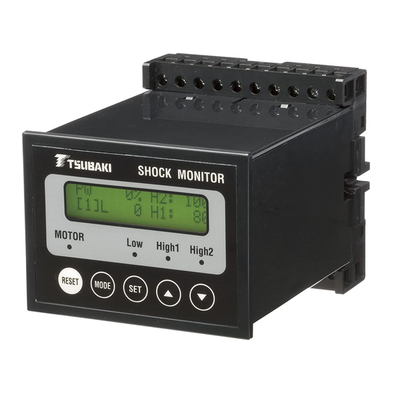
10 Operation 10 Operation 10 Operation 10 Operation LCD display The Shock Monitor TSM4000 LED indicators provides Monitor mode, Test mode, and Program mode, which can be Operation keys selected with the MODE key. 10.1 LED indicators and operation keys Test mode Monitor mode Program mode... -
Page 14: Switching Modes
The Monitor mode is used for load monitoring. Turning on the To change parameters, operational power supply press the MODE key to go to the Program mode TSM4000H2 selection screen. Press POWER ON Ver *.** the SET key to change to the Program mode. Monitor mode... -
Page 15: Test Mode
10.4 Test mode In the Test mode, you can check the operation of the output relays and LED indicators. Since load monitoring is disabled in the Test mode, be sure to return to the Monitor mode after the operation (or after pressing RESET when the relay output is in the self-holding status). - Page 16 ■ Parameter description and setting procedure Parameter Data Description (Default data is shown.) Motor voltage setting (1)200-230V ・ Select (1) to monitor a 200 V class motor. The allowable maximum 1 1 1 1 : : : : M o t o r V o l t a g e M o t o r V o l t a g e M o t o r V o l t a g e M o t o r V o l t a g e...
- Page 17 Parameter Data Description (Default data is shown.) Set the High1 output level. High1 Output is activated when the load ratio reaches 1 to 99% 4 4 4 4 : H i g h : H i g h : H i g h : H i g h 1 1 1 1 L e v e l L e v e l L e v e l...
- Page 18 Parameter Data Description (Default data is shown.) [Time required for detection and output] 8 8 8 8 : S h o c k T i m e : S h o c k T i m e : S h o c k T i m e : S h o c k T i m e ・...
- Page 19 Description Parameter Data (Default data is shown.) ・ Set the cycle to overwrite the monitoring Writing interval 1 to 60 s level. setting 1.1 to 60 min This setting is effective when "(1) Interval" is set for 12: Offset Mode . 1 1 1 1 3 3 3 3 : : : : I n t e r v a l T i m e I n t e r v a l T i m e I n t e r v a l T i m e...
- Page 20 High1 output Start Time 12:Offset Mode (1)Interval Shock Time Reference value Interval time Interval time Interval time RUN indicator SET indicator (LCD) High1 indicator When parameter 6 is set to High1 output relay Self-Hold *1: During the Shock Time period, writing of the operating level is disabled. (The value of the last automatic writing is used for judgment.) *2: If the load continues increasing over the period longer than the writing cycle, High1 does not turn on.
-
Page 21: Troubleshooting
11. Troubleshooting 11. Troubleshooting 11. Troubleshooting 11. Troubleshooting Problem Inspection item Inspection result Countermeasure The LCD display Wiring of the operational No wiring installed. Install the wiring shows nothing. power supply properly. (Between terminals 11 and 12) Operational power supply Less than 90 VAC Provide voltage of 90 to voltage... -
Page 22: Trip Recovery Procedure
Problem Inspection item Inspection result Countermeasure The LED indicator Is the load The load fluctuates greatly and Set the parameters (High1, High2) fluctuation too it instantaneously exceeds the (4, 7, and 10) illuminates, but the great? setting level repeatedly. properly. relay output is not The load does not fluctuate and Repair Shock... -
Page 23: Specifications
16. Specifications 16. Specifications 16. Specifications 16. Specifications TSM4000H2 TSM4000H2P Model number Capacity 0.1 to 110 kW Voltage 3-phase, 200/220 VAC or 400/440 VAC Applicable motor Power supply 5 to 120 Hz frequency Commercial power supply 90 to 250 VAC 50/60 Hz,... -
Page 24: Outer Dimensions
17. Outer Dimensi 17. Outer Dimensions 17. Outer Dimensi 17. Outer Dimensi ■Main unit TSM4000H2 TSM4000H2P Mounting hole dimension Panel cutout dimension ■Current sensor TSM-U010, TSM-U050, TSM-U100 TSM-M300, TSM-M400, TSM-M600 TSM-U150, TSM-U200 TSM-M800 Mounting hole: ø4.6 C u r r e n t d i r e c t i o n m a r k Mounting ho le: 2 - ø4... -
Page 25: Warranty
■Sensor cable ■I/O cable TSM4-S01, TSM4-S03, TSM4-S05 TSM4-C01 TSM4-S10, TSM4-S20, TSM4-S30 TSM4-C03 18. Warranty 18. Warranty 18. Warranty 18. Warranty 18.1 Free warranty period TC shall offer free warranty period of 18 months after the shipment from the factory or 12 months after the beginning of the use (counted from the completion of the installation of the TC product into your equipment), whichever is shorter. - Page 26 MEMO MEMO MEMO MEMO...
- Page 27 MEMO MEMO MEMO MEMO...
- Page 28 Kyoto 617- - - - 0833, Japan Kyoto 617 0833, Japan Kyoto 617 Kyoto 617 0833, Japan 0833, Japan http://tsubakimoto.com/ Internet U.S. Tsubaki Power Transmission, LLC Tsubakimoto Singapore Pte. Ltd. Tsubakimoto Europe B.V. http://www.ustsubaki.com/ http://tsubaki.sg/ http://tsubaki.eu/ Tsubaki of Canada Limited Taiwan Tsubakimoto Co. Tsubakimoto U.K. Ltd.
Need help?
Do you have a question about the TSM4000H2 and is the answer not in the manual?
Questions and answers