
Related Manuals for SmartPower ER-6.2

Summary of Contents for SmartPower ER-6.2
- Page 1 A.C. MODULAR GENERATOR SYSTEM OWNERS MANUAL MODEL#: ER-6.2, ER-8, ER-10 and ER-110 For Compartment or Top Mounting 9991031 Rev. M...
-
Page 2: Table Of Contents
® Smart Power Systems A. C. MODULAR GENERATOR SYSTEM Page 1 of 52 Table of Contents Section Page Disclaimer .......................... 5 Description of Product ...................... 6 System Specifications ...................... 9 Pre-Installation Guide ..................... 11 Installation Guide ......................16 Hose Installation Guidelines ..................20 Operation ......................... - Page 3 ® Smart Power Systems A. C. MODULAR GENERATOR SYSTEM Page 2 of 52 WARNING: Do not install or operate the A.C. modular generator system without reading this entire manual. The A.C. modular generator system will generate enough voltage to produce a fatal electrical shock.
- Page 4 ® Smart Power Systems A. C. MODULAR GENERATOR SYSTEM Page 3 of 52 Never operate the system with leaks of any type. Clean up any hydraulic fluid that is spilled or has leaked out of the system. Hydraulic fluid is combustible, and ignition may occur.
- Page 5 ® Smart Power Systems A. C. MODULAR GENERATOR SYSTEM Page 4 of 52 Use only hoses that meet or exceed the minimum requirements specified in this manual. A ruptured hose can cause personal injury and/or damage to the generator system. Do not operate the system under electrical load with air in the hydraulic fluid (the system will make a growling sound).
-
Page 6: Disclaimer
® Smart Power Systems A. C. MODULAR GENERATOR SYSTEM Page 5 of 52 Disclaimer Although SPS has taken all reasonable care to ensure that the information contained in this installation manual (including without limitation, references, databases, resources, specifications, illustrations and instructions) was accurate in all material respects at the time publication, PROVIDES... -
Page 7: Description Of Product
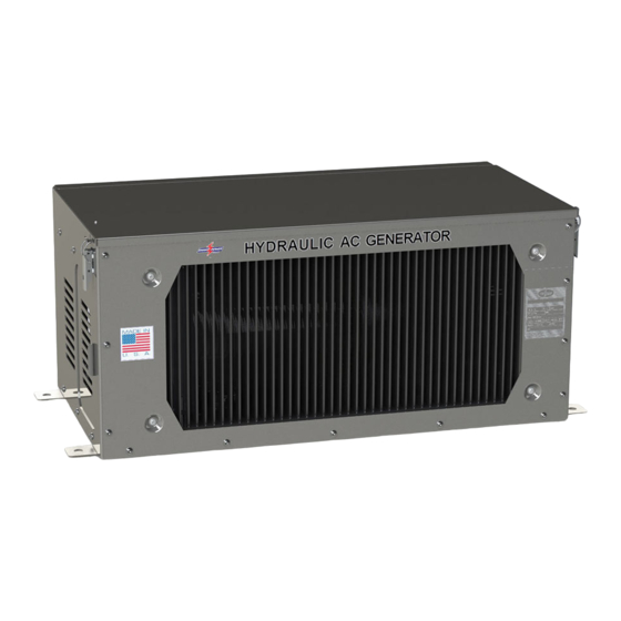
® Smart Power Systems A. C. MODULAR GENERATOR SYSTEM Page 6 of 52 Description of Product Hydraulic Generator Applications: This heavy-duty electronically controlled generator system has been designed to meet the most demanding mobile applications. It provides 120/240 volt AC @ 60 Hz from no-load to full load, handling electrical loads of 6200, 8000 and 10000 watts, depending on model. - Page 8 Smart Power Systems A. C. MODULAR GENERATOR SYSTEM Page 7 of 52 BOOST BLOCK FILTER VENTURI BOOST RESERVOIR COOLER CHECK VALVE MOTOR PROPORTIONAL VALVE PUMP CASE DRAIN CASE DRAIN Figure 1 – Hydraulic Generator Schematic for ER-6.2, ER-8, ER-10 and ER-110...
- Page 9 ® Smart Power Systems A. C. MODULAR GENERATOR SYSTEM Page 8 of 52 Figure 2 – Generator Electrical Schematic for ER-6.2, ER-8, ER-10 and ER-110...
-
Page 10: System Specifications
® Smart Power Systems A. C. MODULAR GENERATOR SYSTEM Page 9 of 52 System Specifications MODEL ER-6.2 ER-8 ER-10 ER-110 GENERATOR Generator AC Inductive AC Inductive AC Inductive AC Inductive Type Speed 3600 RPM 3600 RPM 3600 RPM 3600 RPM... - Page 11 3600 psi, SAE 3600 psi, SAE All Others 1250 psi, SAE 1250 psi, SAE Fittings Dry Weight ER-6.2 235 lbs ER-10 255 lbs (without pump) ER-8 235 lbs ER-110 255 lbs 33 ¾” L x 15 ¾” W x 13 ¾” H 33 ¾”...
-
Page 12: Pre-Installation Guide
® Smart Power Systems A. C. MODULAR GENERATOR SYSTEM Page 11 of 52 Pre-Installation Guide Pre-Installation Check List Verify that the Power Take Off (PTO) and the pump rotations match. To identify the pump rotation, check the pump part number found on the metal tag attached to side of the pump. - Page 13 ® Systems have an SAE B 2 bolt flange. The standard pumps supplied by Smart Power have either a SAE B 7/8” 13 tooth spline for Models ER-6.2, ER-8 and ER- ® Systems 10; OR a SAE B-B 1” 15 tooth spline on the ER-110 model.
- Page 14 ® Smart Power Systems A. C. MODULAR GENERATOR SYSTEM Page 13 of 52 WARNING: Do not install hose ends until proper hose length has been determined. Ensure debris is kept out of the hoses and hydraulic system prior to installation. Never install a hose in a location where it will rub against another surface or abrasion member.
- Page 15 A. C. MODULAR GENERATOR SYSTEM Page 14 of 52 SPS models ER-6.2, ER-8, ER-10 and ER-110 can be mounted on top of a vehicle, in the open, without requiring any additional coverings. Reference Error! Reference s ource not found. for the minimum clearances around the perimeter of the generator’s tray assemble.
- Page 16 ® Smart Power Systems A. C. MODULAR GENERATOR SYSTEM Page 15 of 52 WARNING: Do not mount the hydraulic pump or tray assembly in any location that is not well ventilated. External heat sources elevating the hydraulic fluid and/or the generator temperature will result in premature wear and degraded system performance and void the system’s warranty.
-
Page 17: Installation Guide
Maintain minimum clearances as indicated in, Error! Reference source not found.. Figure 5 – Mounting Hole Pattern for ER-6.2, ER-8, ER-10 and ER-110 Assemblies Mount the tray assembly as high as possible within the structure of the vehicle. The ideal location for the generator is at the top of the truck in the dunnage area. The manufacturer must also take sufficient precautions to ensure that the generator is not mounted in the path of the deck gun/water cannon. - Page 18 ® Smart Power Systems A. C. MODULAR GENERATOR SYSTEM Page 17 of 52 Mount the hydraulic generator tray securely to vehicle. Secure the generator to the floor of the enclosure using hardware (not included), as shown in Figure 6. 1/2-13UNC Screw 1/2”...
- Page 19 ® Smart Power Systems A. C. MODULAR GENERATOR SYSTEM Page 18 of 52 Mount Command & Control Center: a. Create hole pattern as shown in Error! Reference source not found.7. b. Mount Command & Control Center to vehicle using #10 stainless steel button head or cap screw fasteners.
- Page 20 ® Smart Power Systems A. C. MODULAR GENERATOR SYSTEM Page 19 of 52 6. Install hoses and tighten hose ends, using the Hose Installation Guidelines. See Figure 8 for connection locations. Figure 8 – ER-6.2, ER-8, ER-10 and ER-110 Interfaces...
-
Page 21: Hose Installation Guidelines
® Smart Power Systems A. C. MODULAR GENERATOR SYSTEM Page 20 of 52 WARNING: Never operate the system with the pump case drain plugged. Damage to the pump seals will result. To do so will void the system’s warranty. Hose Installation Guidelines Never install a hose without first properly cleaning it to remove debris and contaminants. - Page 22 ® Smart Power Systems A. C. MODULAR GENERATOR SYSTEM Page 21 of 52 Connect the vehicle’s breaker panel to the generator output. The generator is pre- wired to supply 120/240 VAC, with the generator frame bonded to ground. Route the generator output conduit/wiring to the breaker panel, and carefully cut the conduit to length without cutting the wire insulation.
- Page 23 ® Smart Power Systems A. C. MODULAR GENERATOR SYSTEM Page 22 of 52 Figure 9 – 120VAC Alternate Wiring WARNING: Wiring of the A.C. modular generator system and electrical distribution throughout the vehicle must be done in accordance with applicable sections in the National Fire Protection Association’s document NFPA 1901, the National Electrical Code ®...
- Page 24 ® Smart Power Systems A. C. MODULAR GENERATOR SYSTEM Page 23 of 52 Connect 12 VDC (vehicle battery positive) to the generator’s system controller input (reference Error! Reference source not found.8). Connect the RED wire from the s ystem controller, marked “Vehicle +12V supply” to the vehicle’s ignition circuit through a 30 amp fuse.
- Page 25 ® Smart Power Systems A. C. MODULAR GENERATOR SYSTEM Page 24 of 52 c. Fill all hoses with fresh hydraulic fluid before connecting them to the generator system. This will significantly reduce the required time to purge air from the system.
- Page 26 ® Smart Power Systems A. C. MODULAR GENERATOR SYSTEM Page 25 of 52 Enabling System Purge Option The purge option can also be set by performing the following steps: Step 5: Press On/Off Step 3: Hold Mode until y appears. until Amps Line 1 Blinks 88 .
- Page 27 (231) 832-5525 for more information. Also verify that the air passing through the cooler and the fan is not restricted. WARNING: The SPS Model ER-6.2, ER-8, ER-10 and ER-110 have been pre-set at the factory to provide correct frequency and voltage. No pump adjustment is required.
- Page 28 ® Smart Power Systems A. C. MODULAR GENERATOR SYSTEM Page 27 of 52 Set “auto-start” option. If the auto-start option is enabled, the generator will begin generating electricity whenever the PTO is engaged. If the auto-start option is disabled, the generator will not output electricity after PTO engagement until the “on/off”...
-
Page 29: Operation
® Smart Power Systems A. C. MODULAR GENERATOR SYSTEM Page 28 of 52 Operation The Command & Control Center will show the generator’s output voltage, frequency, current, and system run time whenever the Command & Control Center is in the Normal mode. To access Normal mode, press the Mode switch repeatedly until the correct information is displayed (reference Error! Reference source not f ound.4). - Page 30 ® Smart Power Systems A. C. MODULAR GENERATOR SYSTEM Page 29 of 52 If the system controller is powered on, but the generator is not running and no buttons are pressed for 5 minutes, the system will enter Quiescent mode. Quiescent mode all displays are blank to conserve power.
- Page 31 ® Smart Power Systems A. C. MODULAR GENERATOR SYSTEM Page 30 of 52 Additional Information provided by the Command & Control Center: a. When the Command & Control Center is in Normal mode, pressing the Mode switch once will display the oil temperature as in Figure 18, below. Displayed Oil Temperature in degrees Fahrenheit...
- Page 32 ® Smart Power Systems A. C. MODULAR GENERATOR SYSTEM Page 31 of 52 d. Pressing the Mode switch a fourth time will cause the amount of time since the oil filter was last changed to be displayed in the hours field as seen in Figure 21. Time Since last Oil Filter Change in Hours.
- Page 33 ® Smart Power Systems A. C. MODULAR GENERATOR SYSTEM Page 32 of 52 9. Alarms, Shutdowns and Overrides provided by the Command and Control Center The following is a list of diagnostic faults displayed by the Command and Control Center that will cause an automatic shutdown of the system (see the Diagnostic Faults section of this manual for a complete list of diagnostic faults.): a.
- Page 34 ® Smart Power Systems A. C. MODULAR GENERATOR SYSTEM Page 33 of 52 10. The following is an example of how an automatic shutdown can be overridden. This example describes how to override an OIL HOT shutdown, but the override procedure is the same for all the above listed diagnostic faults: Step a: Press Mode to cause rvn and the y and...
- Page 35 ® Smart Power Systems A. C. MODULAR GENERATOR SYSTEM Page 34 of 52 Optional J1939 Interface 1. The integrated SAE J1939 communication interface makes it possible to connect the generator’s ECU to a vehicle multiplexing system for monitoring, control and real time diagnostic information.
-
Page 36: Special Operating Instructions
® Smart Power Systems A. C. MODULAR GENERATOR SYSTEM Page 35 of 52 Special Operating Instructions Cold Weather Procedure: It is strongly recommended that the generator PTO be engaged prior to leaving a heated garage or fire station in cold weather. The system will generate enough heat to keep its hydraulic fluid viscosity low enough for proper operation, in all but the most extremes of low ambient air temperatures. -
Page 37: Maintenance Instructions
® Smart Power Systems A. C. MODULAR GENERATOR SYSTEM Page 36 of 52 Maintenance Instructions WARNING: Do not perform maintenance while system is running. Perform regular, periodic checks to verify: a. The cooler, the cooler fan and generator vents are not plugged by debris. b. - Page 38 ® Smart Power Systems A. C. MODULAR GENERATOR SYSTEM Page 37 of 52 WARNING: Do not by-pass the filter or alter filtration plumbing in any way. Doing so will void the system’s warranty. The system controller automatically records the time from the previous filter change. The hours since the previous filter change can be accessed using the Command &...
- Page 39 ® Smart Power Systems A. C. MODULAR GENERATOR SYSTEM Page 38 of 52 The Command & Control Center will flash a fault when 250 hours have passed since the previous filter change. After replacing the filter, this fault can be removed from the Command &...
-
Page 40: Troubleshooting Guide
® Smart Power Systems A. C. MODULAR GENERATOR SYSTEM Page 39 of 52 Troubleshooting Guide Diagnostic: The Command & Control Center will display certain faults that can assist a service technician in trouble shooting a problem with the generator system. When these faults occur, the fault message will periodically flash on the Command &... - Page 41 ® Smart Power Systems A. C. MODULAR GENERATOR SYSTEM Page 40 of 52 Diagnostic Faults: The following is a list of the diagnostic faults as displayed on the Command & Control Center, with a brief explanation of each. CCC Display Class Description The control valve feedback is invalid, indicating the system is not under...
- Page 42 ® Smart Power Systems A. C. MODULAR GENERATOR SYSTEM Page 41 of 52 The complete list of faults, including conditions and times may be found in Table 4, below. Table 4 – J1939 ECU Fault Conditions Notes: Times are representative. Where more than one proportional valve is used due to flow requirements.
- Page 43 ® Smart Power Systems A. C. MODULAR GENERATOR SYSTEM Page 42 of 52 Hydraulic Problems: Cavitation: Cavitation is caused by trying to pump more fluid than is available at the pump inlet due to system restrictions. Pump cavitation sounds like “marbles” passing through the pump.
- Page 44 ® Smart Power Systems A. C. MODULAR GENERATOR SYSTEM Page 43 of 52 Differential Pressure: Differential pressure between the inlet pressure and the case pressure over 7 psig causes the piston shoes to lift off the swash plate. This occurs due to the excessive lower pressure created on the fill (down) stroke of the piston.
- Page 45 ® Smart Power Systems A. C. MODULAR GENERATOR SYSTEM Page 44 of 52 System Overheating: System overheating may be caused by re-circulation of hot air through oil cooler, dirty or obstructed oil cooler fins, restricted hydraulic fluid flow, excessive generator load, restricted airflow, previously overheated (old) fluid, non-functional fan, or improperly adjusted pump.
- Page 46 ® Smart Power Systems A. C. MODULAR GENERATOR SYSTEM Page 45 of 52 Electrical Problems No Output Voltage: a. No output voltage may be caused by excessive current draw opening the circuit breakers. (The circuit breakers can be found mounted on the generator wiring enclosure.) Remove all electrical loads from the generator and reset breaker(s).
- Page 47 ® Smart Power Systems A. C. MODULAR GENERATOR SYSTEM Page 46 of 52 WARNING: Do not attempt to measure the exciter field resistance while the system is operating. Electrical shock may occur. f. Exciter field capacitors may be faulty. Disconnect the exciter field from the field capacitors.
- Page 48 ® Smart Power Systems A. C. MODULAR GENERATOR SYSTEM Page 47 of 52 Output voltage exceeds 260 volts or falls below 220 volts AC on a 240 volt line: a. Verify that the hydraulic system is not overheating by viewing the temperature as displayed by the Command &...
-
Page 49: Pump Adjustment
® Smart Power Systems A. C. MODULAR GENERATOR SYSTEM Page 48 of 52 Pump Adjustment WARNING: The SPS Electronic Controlled Generators have been pre-set at the factory to provide correct frequency and voltage, no pump adjustments are required. If it appears the pump need to be adjusted, contact SPS at (231) 832-5525 before proceeding. - Page 50 ® Smart Power Systems A. C. MODULAR GENERATOR SYSTEM Page 49 of 52 Pump adjustment procedure: Enable the generator Pump Set option. The system controller has been designed to provide a Pump Set option. With this option applied, the generator will turn at the maximum speed allowed by the hydraulic pump to allow proper adjustment of the pump’s flow.
- Page 51 ® Smart Power Systems A. C. MODULAR GENERATOR SYSTEM Page 50 of 52 Adjust pump compensator: a. Loosen and remove flow control cap. Reference Figure 33. b. Loosen the flow control pressure jam nut. c. While monitoring the generator’s output voltage, slowly rotate the flow control set screw with a 3mm hex wrench.
- Page 52 Press the On/Off button until an appears, indicating Pump Set option is inactive. d. Put system into Normal mode by pressing the Mode button. NOTE: For a complete copy of Manufacturer’s Warranty please see our website at: www.smartpower.com/warranty...
-
Page 53: Sps Model Matrix
A. C. MODULAR GENERATOR SYSTEM Page 52 of 52 SPS Model Matrix The following table includes all generator models this manual applies to: PARENT DESCRIPTION 1700006 GENERATOR, ER-6.2/45cc, R, SPL PUMP 8570006 8510010 1701006 GENERATOR, ER-6.2/45cc, R, KEY PUMP 8570006 8510013 1710006 GENERATOR, ER-6.2/45cc, L, SPL PUMP...
Need help?
Do you have a question about the ER-6.2 and is the answer not in the manual?
Questions and answers