Table of Contents
Advertisement
Spirent C1 and C2 Installation
Instructions
Refer to the Release Notes for information on supported software applications and
versions.
Note: Spirent C1 and Spirent C2 may be abbreviated as SPT-C1 and SPT-C2 in this
document.
•
•
•
•
•
•
•
•
•
PN 71-008959 Rev A April 2020
Certifications and Standards . . . . 4
Requirements . . . . 6
System Description . . . . 10
Rack Mounting Considerations . . . . 21
Connecting to the SPT-C1 and SPT-C2 . . . . 22
Appliance Firmware Support . . . . 29
Using Authenticate Mode (optional) . . . . 32
Related Documentation . . . . 35
How to Contact Us . . . . 36
Spirent C1 and C2 Installation Instructions
|
1
Advertisement
Table of Contents

Subscribe to Our Youtube Channel
Related Manuals for Spirent C1

Summary of Contents for Spirent C1
-
Page 1: Table Of Contents
Spirent C1 and C2 Installation Instructions Refer to the Release Notes for information on supported software applications and versions. Note: Spirent C1 and Spirent C2 may be abbreviated as SPT-C1 and SPT-C2 in this document. • Certifications and Standards ..4 •... - Page 2 Software which it supplies will operate in material conformity with the specifications supplied by Spirent for such Software for a period of ninety (90) days from the date of delivery (the “Software Warranty Period”). The “Product Warranty Period” shall mean the Hardware Warranty Period or the Software Warranty Period, as applicable.
- Page 3 à la terre, les objets métalliques chauffent, ce qui peut provoquer des blessures graves ou souder l'objet métallique aux bornes. Calibration At the time of manufacture, all components manufactured by Spirent Communications are calibrated in accordance with applicable procedures. Spirent Communications equipment is calibrated using national standards, consensus standards, and ratio-type measurements...
-
Page 4: Certifications And Standards
Certifications and Standards Spirent C1/C2 complies with the limits for a Class A digital device in accordance with Part 15 of the FCC Rules. These limits are designed to provide reasonable protection against harmful interference when this equipment is operated in a commercial environment. - Page 5 EN 60950 — “Safety of Information Technology Equipment” This product carries the cTUVus mark. Environmental Considerations This label is on all Spirent-provided electrical and electronic products that are sold and shipped (see Figure Figure 1. Waste of Electrical and Electronic Equipment (WEEE) Label This label indicates that the product contains material that presents an environmental concern.
-
Page 6: Requirements
Spirent C1 and C2 Installation Instructions Requirements Requirements This section describes the Spirent C1 and Spirent C2 system requirements, cable requirements, and network connectivity. Refer to “System Description” on page 10 component descriptions. SPT-C1/SPT-C2 System Requirements SPT-C1/SPT-C2 requires standard AC input of 100-240V~, 6A, 50/60Hz. - Page 7 Spirent C1 and C2 Installation Instructions Requirements Test Ports Table 1 lists the NIC configurations for the Spirent C1 test ports. Table 2 lists the NIC configurations for the Spirent C2 test ports. The SPT-C1 ports are described under “Connector Panel” on page...
- Page 8 Spirent C1 and C2 Installation Instructions Requirements Table 1. NIC Configurations for SPT-C1 Appliance Models (continued) Appliance Model 10/100M Test 1 GbE Test 2.5/5GbE 10 GbE Test Part Ports Ports Test Ports Ports Number SPT-C1 4 x 1GbE NIC-33 and...
- Page 9 Spirent C1 and C2 Installation Instructions Requirements Table 2. NIC Configurations for the SPT-C2 Appliance Appliance 10/100M 1 GbE Test 2.5/5GbE 10 GbE 802.11AX 802.11A Model Part Test Ports Ports Test Ports Test Ports 2.4GHz X 5GHz Number Test Ports...
-
Page 10: System Description
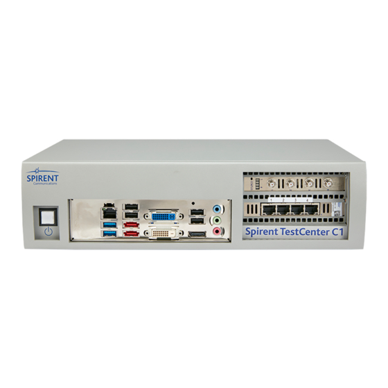
The SPT-C1/SPT-C2 hardware is maintenance-free and should not be disassembled. Servicing the units yourself jeopardizes your warranty. Connector Panel This section shows the connector panels and describes the necessary cabling. SPT-C1 supports NIC configurations for the test ports, as listed in Table 1 on page... - Page 11 SPT-C1 4 x 1GbE (NIC-33) The connector panel is shown in Figure Figure 3. SPT-C1 4 x 1GbE Connector Panel (NIC-33) The network data cables (customer supplied) connected to these ports must be as follows: • Ethernet CAT-5 cable for the management port (Eth0) •...
- Page 12 (NIC-43) The connector panel is shown in Figure Figure 5. SPT-C1 4 x BroadR-Reach Connector Panel (NIC-43) The network data cables (customer supplied) connected to these ports must be as follows: • Ethernet CAT-5 cable for the management port (Eth0) •...
- Page 13 SPT-C1 2 x 10GbE and 4 x 1GbE (NIC-27 and NIC-33) The connector panel is shown in Figure Figure 6. SPT-C1 2 x 10GbE and 4 x 1GbE (NIC-27 and NIC-33) The network data cables (customer supplied) connected to these ports must be as follows: •...
- Page 14 NIC-52) The connector panel is shown in Figure Figure 7. SPT-C1 4 x 1GbE and 802.11 AC/ACN WAVE-1 WiFi (NIC-33 and NIC-51/NIC-52) The network data cables (customer supplied) connected to these ports must be as follows: • Ethernet CAT-5 cable for the management port (Eth0) •...
- Page 15 SPT-C1 4 x 1GbE and 802.11 AC WAVE-2 WiFi (NIC-33/NIC-63 and NIC-56/NIC-57/NIC-60) The connector panel is shown in Figure Figure 9. SPT-C1 4 x 1GbE and 802.11 AC WAVE-2 WiFi (NIC-33/NIC-63 and NIC-56/NIC-57/NIC-60) The network data cables (customer supplied) connected to these ports must be as follows: •...
- Page 16 For test ports (1-8) • Copper: RJ45 connector, Ethernet CAT-5e or better cable Note: Refer to the Spirent C1 and C2 Quick Reference for additional details about the SPT-C2 cables and connectors. Spirent C1 and C2 Installation Instructions PN 71-008959 Rev A April 2020...
- Page 17 SMA connector, 50 OHM RF Cable for Conductive Mode • SMA connector, SMA Male RF Antenna for OTA Mode Note: Refer to the Spirent C1 and C2 Quick Reference for additional details about the SPT-C2 cables and connectors. PN 71-008959 Rev A April 2020...
- Page 18 Spirent C1 and C2 Installation Instructions System Description SPT-C2 NIC-70-V2 Physical Ports Assignment Port 8 Port 7 Port 6 Port 5 (5GHz) (5GHz) (5GHz) (5GHz) Port 4 Port 3 Port 2 (5GHz Port 1 (5GHz + (5GHz + (5GHz + + 2.4GHz)
- Page 19 Figure 14. SPT-C2 NIC 70-V2 System Ports Assignment (2-Radio Profile) Power Supply The power supply for the SPT-C1 and SPT-C2 is controlled by the power button on the front of the unit. The power cord socket is on the back of the unit. Refer to...
- Page 20 (Figure 15 on page 19) to turn on the appliance. The typical boot time is two (2) minutes. Package switch times (switching from Spirent TestCenter to another product, or from another product to Spirent TestCenter) and firmware upgrades take approximately 10-15 minutes.
-
Page 21: Rack Mounting Considerations
Spirent C1 and C2 Installation Instructions Rack Mounting Considerations Site Selection The Spirent SPT-C2 is a network testing device that should be installed in a dust free and dry environment with adequate airflow, power, and cooling. • SPT-C2 is designed with front to rear airflow and both ventilation locations must remain unobstructed for proper operation. -
Page 22: Connecting To The Spt-C1 And Spt-C2
Spirent C1 and C2 Installation Instructions Connecting to the SPT-C1 and SPT-C2 Connecting to the SPT-C1 and SPT-C2 SPT-C1/SPT-C2 connect and operate through your local network much like a standard PC. It boots with the IP address and subnet mask: . If you 192.168.0.100/255.255.255.0... - Page 23 Admin Port Figure 19. SPT-C2 Administrative Port Note: The hardware “Rev” letter for your SPT-C1 model is on the label on the bottom of the appliance. The SPT-C2 model and hardware “Rev” letter are on the label on the bottom of the appliance.
- Page 24 Use a communication program to SSH (secure shell) over the Ethernet administration port to the SPT-C1 default IP address. • The SPT-C1 default IP address is 192.168.0.100, with a netmask of 255.255.255.0 Spirent C1 and C2 Installation Instructions PN 71-008959 Rev A April 2020...
- Page 25 Spirent C1 and C2 Installation Instructions Connecting to the SPT-C1 and SPT-C2 Whichever method you use to connect to the appliance, you will be prompted to log in when the appliance is fully booted up. Use the following system administrator login / password: •...
- Page 26 GUI or script can access the appliance. admin(hypervisor)>>reboot – Applies your settings and reboots the appliance. When the SPT-C1/SPT-C2 appliance restores, after the power cycle or reboot, it is ready for use with the product’s GUI or an automation script (if supported in your current release).
- Page 27 Spirent C1 and C2 Installation Instructions Multiple Chassis and External Time Reference (ETR) Connectors on SPT-C2 External Time Reference Serial DCE Table 3 lists the pin assignments for the External Time Reference Serial DCE (RJ-45) connector. Table 3. External Time Reference Serial DCE Pin Assignments...
- Page 28 Spirent C1 and C2 Installation Instructions Multiple Chassis and External Time Reference (ETR) Connectors on SPT-C2 1588 (RJ-45) Connector Table 6 lists the pin assignments for the 1588 (RJ-45) connector. Table 6. 1588 (RJ-45) Pin Assignments Signal TXRX D0+ TXRX D0-...
-
Page 29: Appliance Firmware Support
Appliance Firmware Support Appliance Firmware Support With the dual boot feature, you can switch between two installed versions of Spirent TestCenter using the command line interface. You can identify the current version and standby version using the appropriate commands described in this section. - Page 30 With the AutoFallBack feature, the supported appliance will switch back to the previously installed version of Spirent TestCenter, if there is a firmware upgrade failure. You will see AutoFallback messages in the Firmware Management tab and the Log window. A warning message will display in the lower right of the pane.
- Page 31 Notes: • feature. • Spirent TestCenter versions below 5.07 do not support AutoFallBack. To see the available Spirent TestCenter versions using the command line interface: SSH to Spirent TestCenter as an admin. Use the applicable command • Type version to identify the active Spirent TestCenter version.
-
Page 32: Using Authenticate Mode (Optional)
When authenticate is “on” or “reset,” a password must be generated using simple ascii text, but it cannot be left blank. Once the password is generated, the Spirent TestCenter GUI or API user will be required to enter the generated password when they attempt to connect to the chassis or appliance. - Page 33 Spirent C1 and C2 Installation Instructions Using Authenticate Mode (optional) Table 7. Spirent C1 and C2 Admin Commands Command Description activate [[<deviceName>]<ipaddress> Save and activate the network configuration <netmask> <gwaddress>] | [dhcp] | [ipv6 [<deviceName>] <ipv6addres> <ipv6gwaddress>] authenticate [on|off|reset] Enable | Disable | Reset authenticate mode console <vm name>...
- Page 34 Spirent C1 and C2 Installation Instructions Using Authenticate Mode (optional) Table 7. Spirent C1 and C2 Admin Commands (continued) Command Description ping6 <ipv6address> Ping an IPv6 address Display or change the ptp settings reboot Reboot the system recovery <chassis|tm> <enable|disable>...
-
Page 35: Related Documentation
Related Documentation Additional documentation related to this guide are listed below. • Spirent C1 and C2 Quick Reference (DOC10339) – Provides a summary of the major steps you use to set up an SPT-C1 or SPT-C2 appliance. • Release Notes – Contain information that may affect product installation, test configuration, or test results, including last-minute requirements or product changes. -
Page 36: How To Contact Us
Phone: +86 (400) 810-9529 (toll-free mainland China only) Phone: +86 (10) 8233 0033 (China) Hours: Monday through Friday, 09:00 to 18:00, Beijing Time Information about Spirent Communications and its products and services can be found on the main company website at https://www.spirent.com. Company Address Spirent Communications, Inc.
Need help?
Do you have a question about the C1 and is the answer not in the manual?
Questions and answers