
Related Manuals for TouchStar MAN067-06

Summary of Contents for TouchStar MAN067-06
- Page 1 EVOLUTION DOOR CONTROLLER (UNIVERSAL) INSTALLATION AND MAINTENANCE GUIDE MAN067-06 DECEMBER 2018...
-
Page 2: General Information
GENERAL INFORMATION IMPORTANT SAFETY INFORMATION This door controller has been designed to meet international safety standards but, like any electrical equipment, care must be taken if safety is to be assured. Read these safety instructions before installation and operation of the door controller. Retain this installation guide for future use. -
Page 3: Table Of Contents
CONTENTS GENERAL INFORMATION IMPORTANT SAFETY INFORMATION POWER REQUIREMENT INTRODUCTION INTRODUCTION SITING THE DOOR CONTROLLER LOCATING THE DOOR CONTROLLER CABLING DIMENSIONS DOOR CONTROLLER PCB CONNECTIONS PCB WIRING AND LINKS DIAGRAM PCB249ASX CONNECTING A READER READERS PIN PAD CONNECTING A LOCK FAIL OPEN LOCK RELAY CONTACTS FAIL CLOSED LOCK CONNECTING SWITCHES &... -
Page 4: Introduction
INTRODUCTION This guide provides the information necessary to install a door controller. It includes mounting and cabling requirements and instructions to enable the device to be commissioned. The door controller communicates over TCP/IP and is fully ‘intelligent’, so that it continues to operate normally when it is unable to communicate with the PC. -
Page 5: Siting The Door Controller
SITING THE DOOR CONTROLLER LOCATING THE DOOR CONTROLLER... The door controller should be located in a position away from extremes of heat, dust vibration and fumes. It should be protected from excessive condensation, hosing and direct sunlight. Choose a location as near as possible to both Reader and the device to be operated, that will allow room for maintenance. -
Page 6: Door Controller Pcb Connections
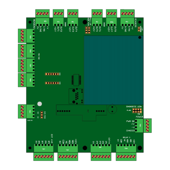
DOOR CONTROLLER PCB CONNECTIONS... -
Page 7: Connecting A Reader
CONNECTING A READER READERS... The main type of reader that the door controller is designed to use is proximity. However, it will also work with standard clock/data interface, magnetic stripe and barcode readers. Our most common readers are listed below together with connection details. -
Page 8: Connecting A Lock
CONNECTING A LOCK The relay contacts have in built protection against transient spikes but when using a pure inductive load with no back EMF protection, extra protection must be fitted. This can be in the form of a metal-oxide varistor (MOV) or diodes (supplied). The positive (+) supply of an inductive load should be connected to the cathode of the diode and the negative (-) to the anode. -
Page 9: Fail Closed Lock
CONNECTING A LOCK FAIL CLOSED LOCK... The fail closed lock requires power to be applied to open it. If power fails, the door will be fail locked. The door controller applies power to the lock when a valid card is swiped. The lock is released and the door can be opened. This type of lock is suitable for the external doors of a building, although it should be noted that in a handle or break glass should always be provided for emergency egress. -
Page 10: Outputs
CONNECTING SWITCHES & I/O OUTPUTS... These are open collector transistors which can drive a load connected to the internal 12V 12V supply or an external supply of up to 12V 12V. When the output is ON ON it can sink a current of 100mA 100mA 100mA... -
Page 11: Commissioning The Door Controller
COMMISSIONING THE DOOR CONTROLLER CONNECTING POWER... The Door Controller should be connected using 3A 240V PVC sheathed cable, from the internal fused terminal block, to an easily accessible isolating device as follows:- Connect the LIVE (BROWN) LIVE (BROWN) LIVE (BROWN) LIVE (BROWN) wire to the terminal marked L L L L (LIVE) in •... -
Page 12: Care And Maintenance
PREPARATION... To ensure the best performance from the door controller and associated readers it is essential to use only good quality magnetic stripe, proximity or barcode media. Contact your dealer or TouchStar customer service department for information about the preparation of badges or other media. In particular, check that cards and badges are flat, smooth and in good condition, that the ink used for bar code... - Page 13 HEAD OFFICE REPAIRS TouchStar ATC TouchStar ATC Access | Time | CCTV Access | Time | CCTV Maple Barn, Unit 49,Vinehall Business Centre, Beeches Farm Road, Vinehall Road, Uckfield, Robertsbridge, East Sussex TN22 5QD East Sussex TN32 5JW T: 0845 3379 155 E: support@touchstar.co.uk...
Need help?
Do you have a question about the MAN067-06 and is the answer not in the manual?
Questions and answers