Table of Contents

Related Manuals for TPC ERN T Series


Summary of Contents for TPC ERN T Series
- Page 1 COIL WINDING MACHINE ERN T-VERSION OPERATING INSTRUCTIONS Version: 1.3 Date: 11.6.2019 ERN 100T, 200T TPC s.r.o Pálenica 53/79 03301 Liptovský Hrádok SLOVAKIA Tel.: +421-44-5221366 Fax: +421-44-5222088 E-mail: tpc@tpc.sk www.tpc.sk...
-
Page 2: Table Of Contents
1. Introduction 1.1 Characteristic features 2. Technical data 2.1 Climatic conditions 3. Description of machine 3.1 Description of controls 3.2 Description PC display 4. Installation and preparation of working equipment 4.1 Mechanical installation 4.2 Power connection 4.3 UPS 4.4 Machine preparation for running 5. - Page 3 7.5 Special functions 7.5.1 Layer-stop 7.5.2 Layer end 7.5.3 Warning 7.5.4 Automatic correction 7.5.5 Automatic switch to manual regime 7.5.6 Trapezoidal winding 7.6 Auxiliary inputs and outputs 7.6.1 Window for inputs and outputs 7.6.2 Digital inputs programming 7.6.3 Digital outputs programming 8.
-
Page 4: Introduction
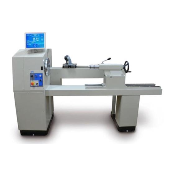
1. INTRODUCTION Floor type universal coil winding machine ERN is designed for winding heavy coils, transformers, chokes, resistors etc with wire up to diameter of - see technical data. 1.1 Characteristic features: - 15" industrial capacitive touch screen for data display and programming - wide range of application for winding simple or complicated coils, multi-chamber coils, trapezoidal or asymetric windings - AC servo, that is used like a spindle drive assures excellent dynamical parameters,... -
Page 5: Climatic Conditions
ERN 100 ERN 200 2. TECHNICAL DATA Pitch range (mm/rev): 0,000 - 160 0,000 - 160 Winding width (mm): 400-800-1200 400 - 800 - 1200 Winding speed / torque [rpm/Nm]: 150 / 270 600 / 75 75 / 540 300 / 150 Accuracy of spindle stop [rev]: 0,01 0,01... -
Page 6: Description Of Controls
3.1 Description of controls 1 - POWER ON / OFF switch 2 - EMERGENCY STOP - disconnects power in emergency 3 - POWER ON indicator 4 - START button - starts the winding cycle 5 - STOP button - interrupts the winding cycle 6 - JOYSTICK 7 - MANUAL button 8 - Connector for foot pedal... - Page 7 Monitor cables assembly COM1 Control elements 4 / ERN T / V 1.3...
- Page 8 POWE R TOTAL STOP BRAKE U P S 5 / ERN T / V 1.3...
-
Page 9: Description Pc Display
3.2 Description of PC display Display provides two basic views for standard information during winding: Winding window and Programming window. Switching from Winding to Programming window it is necessary to touch central display place. Switching back - touch ENTER button. Winding window Programming window In order to work with a PC we can use the supplied mouse, which we plug into the USB port . -
Page 10: Installation And Preparation Of Working Equipment
4. INSTALLATION AND PREPARATION OF WORKING EQUIPMENT 4.1 Mechanical installation The winding machine is fixed to the transport wooden pallet. It is necessary to prepare a level balanced surface for its final location. The both frame surfaces must be balanced horizontal in one surface. -
Page 11: Ups
4.3 UPS The UPS is alive constantly, if the main switch (10) is in off-position, as well. In common running the UPS must be switched on constantly. In case of continual fall-out loss of the line voltage, e.g. electric distribution breakdown, repairs and re-designs or when the running is dead, it is necessary to set the UPS to off, that the useless discharge of storage batteries does not arise. -
Page 12: Winding Operation
5. WINDING OPERATION 5.1 Switching the machine on and gear setting After switching on (1) the start window appears 28.5. 2015 11:45 OPERATOR LOGIN After pressing "OPERATOR" it is possible to choose operator name and continue by pressing START. This window appears only if you choose operator login (see chap. 13.) 20.4.2011 8:30 OPERATOR : operator 1 OPERATOR... - Page 13 The gear change requires the use of password - Master code (listed in the warranty card) as a confirmation that the change is done by an authorized person. After pressing ENTER the initial setup is complete. This means that the wire guide is shifted to left home (zero) position - zero number of turns, step 0 and the last programme is set.
-
Page 14: Backup Of Winding Data In Case Of An Electricity Drop
5.2 Backup of winding data in case of an electricity drop In this window the initial setting of the machine (wire guide position, number of turns and step) can be activated. After the activation of this function (MEM.POS.ON) will be updated with values as they were before the electricity drop. -
Page 15: Winding And Programming Window
5.3 Winding and programming window There are two basic windows. Winding window - provides actual information about the winding process Actual state Winding corrections Step Number of turns Wire guide position and direction Next step Steps list Terminal Coil name Exit Step change Pedal speed... -
Page 16: Winding Programme Selection
5.5 Winding programme selection The winding programme we are currently using with (winding or programme creation can be performed) is called ACTUAL PROGRAMME. Actual programme is located in so-called working part of memory. Desired winding programme can be loaded to the working part of memory either from PC memory, USB flash drive or a LAN network. -
Page 17: Foot Pedal
5.7 Foot pedal Winding machine may be equipped with the following types of foot pedal: Double foot pedal controls START, BRAKE RELEASE - left pedal releases the spindle brake - right pedal works in parallel with the START-button Double foot pedal controls SPEED, BRAKE RELEASE - left pedal releases the spindle brake - right foot pedal controls spindle speed depending how hard the pedal is pressed. -
Page 18: Security Measure - Optosensor
If we require the same maximum pedal speed as speed programmed in the current programme step, we need to press the PARAMETERS FROM PROGRAM button. Max. pedal speed is controlled by values programmed in individual programme steps. Winding cycle start continuity This option is utilized during winding start. -
Page 19: Winding Corrections
5.9 Winding corrections Program corrections and adjustments are allowed only in the state "STANDSTILL" or "Winding STOP". Keys are blocked in other states. 5.9.1 Spindle reference position setting The spindle can be positioned in the range + - a few degrees and exact position is kept for any amount of windings. -
Page 20: Wire Guide Relative Position Setting
5.9.2. Wire guide relative position setting This correction shifts zero coordinate of the wire guide (relative zero position). It allows you to correct the wire guide position to be in accordance with the bobbin or winding tool. Default: 5 mm the same wire guide coordinate depending on relative position 0 0 0 relative zero... -
Page 21: Number Of Turns Correction
5.9.3. Number of turns correction It is possible to change the number of turns actually counted. Correction of decimal and hundredths turn number e.g. XX.36 to XX.30 without adequate spindle turn, leads to the loss of reference position. Pressing the RESET button will change the actual number count to zero. 5.9.4 Total counter We can switch between TOTAL COUNTER and COUNTER. -
Page 22: Wire Guide Correction
5.9.5. Wire guide correction This allows you to correct the wire guide position during the winding process. Holding any of the the buttons pressed (cca 0,5 s) moves the wire guide continuously. 5.9.6. Wire guide direction change This allows you to change the direction of wire guide during winding. 19 / ERN T / V 1.3... -
Page 23: Abort Step
5.9.7. Abort step This allows you to abort current running step. By pressing the ABORT STEP button the machine will return to the STANDSTILL state. 5.9.8. Back winding This allows you to wind back the required number of turns. We can wind back the number of turns required only by using the pedal. The number of turns is counted back and the wire guide moves in opposite direction. -
Page 24: Deceleration Ramp For The Stop-Button
5.9.9. Deceleration ramp for the STOP-button Deceleration ramp for the STOP button can be set. This ramp is slightly faster than programmed deceleration ramp. This is controlled by the software. Code table CODE TIME (s) Presentated values are valid for max.speed. 5.9.10. -
Page 25: Joystick
6.JOYSTICK Each model is equipped with a four way JOYSTICK which provides the following actions: - wire guide corrections S T E P + W I R E R I G H T G U I D E I N G W I N D I R E E C T I O... - Page 26 - return one step back and wire guide direction change S T E P + I N G W I N D E C T I O C O R R GO BACK S T E P + GUIDE POSITION R E C T I O U I D E D I W I R E G...
-
Page 27: Programming
7. PROGRAMMING Entering the data: Value Parameter Use the ENTER button to execute the entered value or to return from any function. Programming is not possible in step 00. In order to move to a particular step, either use the or use the numeric keyboard. -
Page 28: Basis Of Programming
7.1 Basis of programming The winding programme is a logical sequence of a few (1-350) joined steps. winding winding shift shift step 1 step 2 step 3 step 4 Joining to the next step is defined by the type of cycle. If the type of cycle "END " is programmed within a specific step, this will end the programme. -
Page 29: Step Parameters Programming
7.2 Step parameters programming 7.2.1 Basic step types Every step can be programmed as SHIFT, WINDING, JUMP, DELAY or GEAR. Shift - spindle is not turning and the wire guide is shifting to the programmed coordinate Winding - defined by the following parameters: number of turns, speed and spindle direction, pitch, left and right reversal point Jump - spindle is not turning and the wire guide is shifting from its position to the left or right, in accordance with the programmed value... - Page 30 Type of cycle Set the type of cycle and choose, how to continue to the next step. End of program By pressing START-button, program is restarted and step 1 is running. Cycle stop After step finish, program stops and the next step is activated by START-button.
-
Page 31: Winding Step
7.2.3 Winding step Number of turns Assignment of the layer Cancelantion of the previous No. of turns Wire guide direction after start Cancelation of the previous number of turns CANCEL - previous counted number of turns is cancelled after START-UP of the winding step type CANCEL - counted number of turns is not cancelled Wire guide direction after start -right moving the wire guide after START -UP if its position is between left and right reversal point... - Page 32 Spindle speed ,direction ,acceleration ,deceleration, and protection shield Spindle acceleration,deceleration Spindle direction programming Protection shield programming 780,00 0,00 0,00 0,00 Enter values between 1 and 8 for acceleration and deceleration according to the table below: CODE ACCEL. DECEL. ( s ) ( s ) 29 / ERN T / V 1.3...
- Page 33 Pitch 780,00 0,000 PROGRAM PROGRAM Left reversal point PROGRAM PROGRAM Right reversal point PROGRAM PROGRAM 30 / ERN T / V 1.3...
- Page 34 Switching OFF the wire guide shifting during programming The wire guide shifting can be switched OFF by pressing the SHIFTING ON/OFF button during programming. PROGRAM PROGRAM Type of cycle Set the type of cycle and choose how to continue to the next step. PROGRAM PROGRAM STOP...
-
Page 35: Wire Guide Jump
7.2.4 Wire guide jump Lenght of jump and direction PROGRAM Type of cycle PROGRAM PROGRAM 32 / ERN T / V 1.3... -
Page 36: Delay
7.2.5 Delay Time of delay PROGRAM Type of cycle PROGRAM PROGRAM 33 / ERN T / V 1.3... -
Page 37: Display And Assignment Of The Layer
7.3 Display and assignment of the layer The number of layers can be displayed . Readout showed on display can be switched as follow : PROGRAM The layer number of every step can be assigned according to winding instruction. The same number of layer can be assigned to a few consecutive steps. -
Page 38: Programming Corrections
PROGRAM 7.4 Programming corrections The following functions simplify programming or corrections. 7.4.1 Insert empty step An empty step can be inserted anywhere within the programme. It can then be completed with the required parameters. Subsequent steps are shifted in value " +1" automatically. ENTER JUMP Position for step insertion is chosen by buttons... -
Page 39: Delete Step
7.4.2 Delete step Each step in the programme can be canceled. Subsequent steps are shifted in value " -1" automatically. EMPTY STEP JUMP Step, which we wish to cancel can be chosen by buttons 7.4.3 Copy step Each already programmed step can be copied to another step ( previous or next). EMPTY STEP Current step is copied and inserted to the step, which can be chosen by buttons 37 / ERN T / V 1.3... -
Page 40: Global Change
7.4.4 Global change This function allows you to change one chosen parameter in all the subsequent steps. These must be of the same type. Eg.: if the current step is winding, the chosen parameter will be changed in all subsequent winding steps. This is valid for all other step types ( SHIFT, JUMP, PAUSE ). PROGRAM Choose a parameter to be changed - eg. -
Page 41: Coordinate Offset
7.4.5 Coordinate offset This correction provides offset for all coordinates in the programme to the left or right of the entered value. All programmed coordinates (left,right reversal points and shifts) are increased by the value of 20,0 mm. 39 / ERN T / V 1.3... -
Page 42: Special Functions
7.5 Special functions 7.5.1 Layer stop This function activates winding step STOP after each wound layer. The machine will stop after each layer at both left and right reversal points. This will continue until the programmed number of turns is reached. If the assigned layer is displayed, this function will increase its value automatically after each layer. -
Page 43: Layer End
7.5.2 Layer end This function activates winding step STOP in desired layer in reversal point. The machine will stop in desired layer in desired reversal point and the entire winding step terminates. 7.5.3 Warnings This function allows to write important warning for any step. It shows automatically after step finish and disappears after next pressing START (or pedal). -
Page 44: Automatic Correction
7.5.2 Automatic correction Utilization of this function is mainly related to previous function LAYER STOP. It allows you to correct wire guide position for all subsequent layers. After the first layer is wound (eg. from left to the right), press the wire guide correction button and correct the wire guide position. - Page 45 Maximum value for wire guide correction can not be greater than ± 10 mm after a layer is wound. Value higher than this will be ignored ! 43 / ERN T / V 1.3...
-
Page 46: Automatic Switch To Manual Regime
7.5.5 Automatic switch to manual regime This function will automatically switch manual regime after a certain pre-programmed number of turns have been completed. In the manual regime the winding is done by the foot pedal. The value of the pitch is taken from the current step. -
Page 47: Trapezoidal Winding
7.5.4 Trapezoidal winding This function automatically shifts the reversal points after each layer is wound. Cancelation Trapezoid form change Available form of trapezoidal windings : left trapezoid : OFF right trapezoid : / X,X left trapezoid : OFF right trapezoid : \ X,X left trapezoid : \ X,X right trapezoid : OFF left trapezoid : / X,X... -
Page 48: Auxiliary Inputs And Outputs
7.6 Auxiliary inputs and outputs Machine provides an oportunity to program and control up to 4 auxiliary digital outputs and 4 digital inputs. Digital inputs and outputs are galvanically isolated. Relay is applied in standard equipment. Controller ERN Auxiliary equipment INPUT +12V OUTPUT... -
Page 49: Digital Inputs Programming
7.6.2 Digital inputs programming Each digital input can be programmed as: INPUT NON-ACTIVITED - input is inactive CYCLE INTERRUPTION - winding cycle interrupton is done if input is high (+ 12 V) CYCLE START - winding cycle start is done if input is high (+12 V) CYCLE START BLOCKED - start is blocked while duration of high (+ 12V) 7.6.3 Digital outputs programming The following 3 parameters can be programmed in digital outputs 1 - 4:... - Page 50 Delay 48 / ERN T / V 1.3...
-
Page 51: Steps List
8. STEPS LIST Steps list displays view of programmed steps and provides the following possibility for programming and corrections. - Parameter correction 49 / ERN T / V 1.3... - Page 52 780,00 0,000 PROGRAM Each parameter can be changed in this way. - Insert empty step empty step 50 / ERN T / V 1.3...
- Page 53 - Copy step Pressing of button "COPY STEP" ends copying. 51 / ERN T / V 1.3...
- Page 54 - Delete step 52 / ERN T / V 1.3...
-
Page 55: Programme Saving And Opening
9. PROGRAMME SAVING AND OPENING T-version is equipped with computer control with touch screen and Windows . SSD is used as the storage medium. PC memory space is divided into two partitions C: and D:. The operating system is installed on C:. Access to partition C: is blocked. Partition D: is used for manufacturer application programmes and winding programmes. - Page 56 54 / ERN T / V 1.3...
-
Page 57: Programme Saving
9.2 Programme saving Each programme can have a maximum of 350 steps. Once a programme is created it can then be saved. Provide a name for the programme and save it into directory (or subdirectory). example_8T 55 / ERN T / V 1.3... -
Page 58: Programme Copy
9.3 Programme copy This function allows to copy programmes already created. 56 / ERN T / V 1.3... -
Page 59: Menu
10. MENU Displays and allows the change of some basic settings of the machine. Factory settings Error messages Program locking Monitoring Model selection Language selection PIN code setting Machine number setting Display layer Spindle zero position Accelerations, decel. 10.1 Programme locking Programming can be locked or unlocked by entering MASTER or PIN code. - Page 60 10.2 Error messages If mistakes occur, these will trigger the following error messages: ERROR Microswitch Mechanical displacement of the wire guide. It occurs if the lateral power on the wire guide overcomes the torque of the step motor. Solution: press RESET ERROR Spindle speed versus pitch Pitch or spindle speed is too high (exceeds the max.wire guide speed 75 mm/sec) Solution: press ENTER and correct either spindle speed or pitch...
-
Page 61: Display Language
10.3 Model selection 10.4 Display language Allows a selection of display language. 59 / ERN T / V 1.3... -
Page 62: Winding Machine Number
10.5 Winding machine number Winding machine number can be set for easy network identification. 10.6 Access PIN code setting Available codes for user : - MASTER code - allows you to change all settings in menu. This code is fixed by producer and is referred to guarantee certificate. -
Page 63: Zero Spindle Position Mode
10.7 Zero spindle position mode There are two possibilities for set : - Absolute zero spindle position ON - zero spindle position as set during reset is kept for all winding steps and manual spindle handling - Absolute zero spindle position OFF - zero spindle position starts at actual spindle position and the new one is always set by winding step START 61 / ERN T / V 1.3... -
Page 64: Firmware And Upgrade
11. FIRMWARE AND UPGRADE Upgrade files can be delivered via e-mail. There are two types of upgrade files: - tpccrxxx.tpc – control board upgrade, where xxx is number of version (e.g. tpccr060.tpc) - PC application programme upgrade 11.1. Upgrade of the application programme... -
Page 65: Creation And Modification Of The Operator List
12. Creation and modification of the operator´s list Operator’s name is used for the identification when production log is created. The names and codes information are stored in the file C:\TPC\OperatorNames.ini, this can be edited. Note: never change the header, it has to remain on the first row, in the form [MenaObsluhy] all the following rows have to be in form: numerical code of the operator = name and surname of the operator, e. -
Page 66: Production Log Settings
13. Production log setting 13.1 Production log Create log records – check this option if you want to monitor coil production Operator login – check this option if you want to assign operator names Delete old records automatically – check this option if you want the old records to be deleted automatically and set number of days after which records should be deleted Save production log to file –... -
Page 67: Terminal Mode
13.2 Terminal mode TERMINAL = displays winding instructions Winding procedures are able to provide winding machine operators with additional important information on winding. If a winding programme is accompanied with a corresponding winding procedure a current winding step technological operation description is displayed on the winding machine monitor automatically. - Page 68 14. Software GRAPHIC The GRAPHIC software is a comfortable design program, connected online with a winder. It allows the creation of complicated long programs with an overview of the position of the wire guide and has special features such as layer spread or correction. The operating instructions are supplied with the supplied USB key.
-
Page 69: Package Contents
15. PACKAGE CONTENTS ERN 200 ERN 100 Documents delivered with the machine: Documents delivered with the machine: 1 pc certificate of quality and completeness 1 pc certificate of quality and completeness 1 pc user´s guide 1 pc user´s guide Supplied Accessories: Supplied Accessories: 2 pcs fuse T 315 mA/250 V 2 pcs fuse T 630 mA/250 V...
Need help?
Do you have a question about the ERN T Series and is the answer not in the manual?
Questions and answers