
Related Manuals for Lonking CDM853

Summary of Contents for Lonking CDM853
- Page 1 CDM853 CDM853 CDM853 CDM853 WHEEL WHEEL LOADER LOADER WHEEL WHEEL LOADER LOADER (Joystick Control) OPERATION MANUAL OPERATION MANUAL OPERATION OPERATION MANUAL MANUAL...
- Page 2 In order to offer better services to you and improve product and service quality, you are expected to timely inform us of any problem identified during your use of LONKING products and this Manual, along with any corresponding improvement opinions.
- Page 3 CONTENTS CONTENTS CONTENTS CONTENTS PREFACE ..........................1 CONTENTS ......................... 2 CHAPTER I SAFETY PRECAUTIONS ..............7 1.1DESCRIPTION OF SAFETY SIGNS ............... 7 1.2DESCRIPTION AND LOCATIONS OF SAFETY SIGNS ......... 7 1.2.1 WARNING SIGN OF REVERSING ............8 1.2.2 WARNING SIGN OF THE ANTI- FREEZE FLUID ........ 8 1.2.3 WARNING SIGN OF MAINTENANCE AND TRANSPORTATION ..
- Page 4 1.4.10FIRE EXTINGUISHER AND FIRST-AID KIT ........23 1.4.11PREVENTION OF ROLLING INJURY OR CUT OFF ......23 1.4.12ETHER (IF YOUR MACHINE IS EQUIPPED WITH ETHER COLD STARTING DEVICE) ..............24 1.4.13MAKE SURE A GOOD VENTILATION WHEN OPERATING IN AN ENCLOSED SPACE ............24 1.4.14PIPELINE, HARD PIPE AND FLEXIBLE PIPE ........
- Page 5 1.8.4 ILLUMINATION ................47 1.8.5 FIRE PREVENTION ..............47 1.8.6 PERSONS FOR REPAIR AND MAINTENANCE ......48 1.8.7 ATTACHMENTS ................48 1.8.8 MAINTENANCE UNDER MACHINE ..........49 1.8.9 MAINTENANCE WITH THE FRAME SUPPORTED UP ....49 1.8.10 MAINTENANCE ON THE TOP OF THE MACHINE ..... 49 1.8.11 MAINTENANCE WHEN ENGINE IS WORKING ......
- Page 6 3.12 SAFETY BELT .................... 78 3.13CAB DOOR LOCK ..................78 3.14 USE OF LOCATING LOCK ................. 78 3.15ADJUSTMENT TO REAR-VIEW MIRROR ..........79 3.16 TURNING LAMPS AND FULL-BEAM/LOW-BEAM HEADLIGHTS .... 79 3.17 CHARGING DOCK ..................80 3.18 SUNSHADE ....................80 3.19 PLAYER ......................
- Page 7 LOADER ....................... 116 5.5OIL INFORMATION ..................118 5.6UNIVERSAL TORQUE TABLE ..............119 5.7MAINTENANCE OF THE ENGINE COOLANT ..........119 5.7.1 COOLANT COMPOSITION ............120 5.7.2 ADDING COOLANT ..............121 5.7.3 INSPECT COOLANT LEVEL REGULARLY ....... 123 5.7.4 CLEANING OF COOLING SYSTEM .......... 123 5.7.5 ENGINE AIR FILTER MAINTENANCE ........
- Page 8 CHAPTER CHAPTER CHAPTER I I I I SAFETY SAFETY PRECAUTIONS PRECAUTIONS CHAPTER SAFETY SAFETY PRECAUTIONS PRECAUTIONS Warning! Warning! Warning! Warning! Please read and understand all the safety precautions before operation. Failure to do so may result in severe bodily injury or death. DESCRIPTION DESCRIPTION SAFETY...
- Page 9 These safety signs must be kept clean. If the figures and words on these signs are unclear or illegible, please replace or clean them with soft cloth, water or soapy water. No solvent, gasoline or other irritating chemical agent may be used for this purpose.
- Page 10 Sign location: left side of frame hinge joint � Contents: it reminds the users to lock the � frame with fixing rod before transportation and maintenance of machine, to avoid accidents. Dismount the fixing rod before the loader recovers its work, and place it in fixed location.
- Page 11 Sign location: at both left and right sides of � the engine hood Contents: this sign reminds the user to open � engine hood only when the engine stops in order to avoid severe injury 1.2.7 1.2.7 WARNING WARNING SIGN SIGN TRAMPLE TRAMPLE...
- Page 12 Sign location: left side of the frame hinge � Contents: description of basic information of � the machine 特 征 额定载重量 发动机型号 发动机功率 1.2.10 LIFTING BINDING SIGN 1.2.10 1.2.10 1.2.10 LIFTING LIFTING LIFTING AND AND BINDING BINDING BINDING SIGN SIGN SIGN Sign location: rear end of frame, near tire �...
- Page 13 Sign location: on oil tank at the left side of � the frame Contents: this sign reminds the user that � filled hydraulic oil shall be the oil product designated by LONKING or the hydraulic oil of the same type. 1.2.12 1.2.12 SCHEMATIC SCHEMATIC...
- Page 14 Sign location: on the bucket � Contents: this sign reminds the user that the � permitted capacity of the bucket is less than the figure as shown on the sign. Otherwise, it will cause accidents. 1.2.15 1.2.15 1.2.15 1.2.15 ATTACHMENT ATTACHMENT ATTACHMENT ATTACHMENT NAMEPLATE...
- Page 15 1.2.18 SAFETY EXIT SIGN 1.2.18 1.2.18 1.2.18 SAFETY SAFETY SAFETY EXIT EXIT EXIT SIGN SIGN SIGN Sign location: lift arm � Contents: this sign reminds the user � to operate the machine according to this sign. Otherwise, it may cause machine damage or personal injury.
- Page 16 Sign location: on rear hood � Contents: this sign reminds the user to � operate the machine according to this sign. Otherwise, it may cause machine damage or personal injury. 1.2.21 1.2.21 1.2.21 1.2.21 SIGN SIGN SIGN SIGN OF OF BATTERY BATTERY BATTERY BATTERY CONNECTING...
- Page 17 7. This warning sign reminds the user to use oil dedicated for Lonking loaders or equivalent oil recommended in this instruction book during oil replacement; otherwise machine damage or personal...
- Page 18 MODIFICATION MODIFICATION Any modification of this machine not authorized or approved in writing by LONKING may cause safety accidents. The owner shall bear all the consequences. For the sake of safety, please use correct grade and genuine fitting and oil. If without correct fittings or periodically fasteners change, the parts may exceed safety use limitation.
- Page 19 Observe the surrounding safety influence factor at any instant. Follow related safety regulations. 1.4.2 1.4.2 PROTECTIVE PROTECTIVE DEVICES DEVICES 1.4.2 1.4.2 PROTECTIVE PROTECTIVE DEVICES DEVICES Make sure all protective devices and engine hood is in proper location, if there is damage, timely repair it.
- Page 20 Do not use mobile phone when operating the loader, because distraction may cause accidents. Do not take any flammable and explosive hazardous article into the cab. Do not wear earphone or headphone when driving or operating the loader, otherwise it may cause accident.
- Page 21 fore, it is important to wear mask, protective clothes and safety shoes before using the compressed air. The maximum pressure of compressed air using clean shall be under 0.3MPa. Check whether all protective equipment are in normal work conditions. 1.4.5 GETTING MACHINE 1.4.5...
- Page 22 Please use fuel, oil and hydraulic oil used in hydraulic system to fill diesel engine of this loader, hydraulic transmission oils and gear oils used in transmission system and brake fluid used in brake system and antifreeze used in engine water tank can be lit by open fires, in particular, fuel is flammable and dangerous, therefore, the following Safety and accident prevention must be...
- Page 23 DUST HAZARD HAZARD Inhalation of asbestos dust may be harmful to body health. The products produced by LONKING Holdings Limited do not include asbestos, but if you contact with materials containing asbestos fibers, please follow the below rules: It is protective to use compressed air for cleaning.
- Page 24 1.4.9 FACE MASK EARPLUG 1.4.9 1.4.9 1.4.9 FACE FACE FACE MASK MASK MASK AND AND EARPLUG EARPLUG EARPLUG Never ignore the dangerous factors that may not be harmful to body health at present. Exhaust gas and noise is unseen, but it may cause disability or permanent injury. 1.4.10 1.4.10 1.4.10...
- Page 25 mechanism moves or hydraulic pipeline leaks, any attachment will fall off. Unless otherwise specified, make no adjustment when the machine is operating or the engine is starting. Be sure to keep away from all rotating and moving parts. Be sure that there is no debris in the engine fan blades.
- Page 26 LONKING Holdings Limited. Please carefully check all pipelines, hard pipes and flexible pipes, tighten all joints according to specified tightening torque. Do not check the leakage with bare hands, but check them with board or cardboard.
- Page 27 If the protection device is seriously impacted or damaged, its strength is lowered and its normal functions cannot be reached, please contact the designated dealer of LONKING Holdings Limited for consultation repair method. When using breaker for operation, install a protective device on the front windshield.
- Page 28 replace with a new one immediately. SAFETY SAFETY PRECAUTION PRECAUTION OPERATION OPERATION 1.5 SAFETY SAFETY PRECAUTION PRECAUTION OF OF OPERATION OPERATION 1.5.1 1.5.1 1.5.1 1.5.1 SITE SITE SITE SITE SAFETY SAFETY SAFETY SAFETY Before starting the engine, carefully check whether there is any abnormal condition around the engine leading to dangerous situation.
- Page 29 First, check ground conditions, water depth and flow rate when operating on water or sandy embankment. Do not exceed the allowable water depth. Do not drive or run the machine on the soft road, otherwise, the machine may be difficult to leave. Avoid operating on the cliff edge, suspended material or deep pit, if the ground collapsed, the machine crashed or upset, which may cause...
- Page 30 Check the level of coolant, fuel and oil of engine oil pan, check whether air filter is blocked and cable is damaged. Adjust the operator’s seat to the location where is convenient to operate machine, check whether the positioning device of seat belt and safety belt is damaged. Service lift of the safety belt is over 3 years and replaced Check whether the instruments are in normal working condition, and whether the joystick is in parking position.
- Page 31 1.5.3 ENGINE START-UP 1.5.3 1.5.3 1.5.3 ENGINE ENGINE ENGINE START-UP START-UP START-UP Before ascending the machine, visible inspect your machine, check whether there are persons and objects on, off, or near the machine or on the working area. If the machine has not used for a long time or the operating temperature is extremely low, please maintain your machine before start up.
- Page 32 If a reversing alarm device is installed, make sure it is in normal working condition. 1.5.4 CHECK AFTER ENGINE STARTING BEFORE MACHINE 1.5.4 1.5.4 1.5.4 CHECK CHECK CHECK AFTER AFTER AFTER ENGINE ENGINE ENGINE STARTING STARTING STARTING UP UP AND AND BEFORE BEFORE BEFORE MACHINE...
- Page 33 Before operating the machine, again check the states around the machine, make sure there is nobody and obstacle there. When the machine is running, sound the horn for warning. Only when the operator sitting down to the seat that can start and operate the engine. Fasten the safety belt.
- Page 34 Right and left glance is dangerous when operating the machine; therefore, the operator shall concentrate on his work. Too fast traveling, sudden start, sudden stop, sudden turn or zigzag traveling is dangerous. Adjust the height of working device below the lift arm and keep a clearance of 500-600mm (20- 24in) from the hinge pin and ground, let the machine travel on the level ground.
- Page 35 Sound the horn to warn the staff and person in the field. Check the vicinity of the machine to ensure that there is nobody. Pay special caution to check the back area of the machine, for this area is unclear to see from the operator’s seat.
- Page 36 machine at a low speed. The machine must move straight up and down when traveling on the slope. When the machine travels downhill, never shift gear or place the gear in a “neutral” position. It is dangerous not to use the braking force of the engine. When the machine begins to travel downhill, the gear has to be placed in a “low”...
- Page 37 1.5.10 BEWARE HIGH VOLTAGE CABLES 1.5.10 1.5.10 1.5.10 BEWARE BEWARE BEWARE OF OF HIGH HIGH HIGH VOLTAGE VOLTAGE VOLTAGE CABLES CABLES CABLES Do not let the machine touch the overhead cables, even near the high voltage cable can cause electric shock. Keep a safe distance between the machine and cable as shown in the following table.
- Page 38 PRECAUTION OPERATION 1.6 PRECAUTION PRECAUTION PRECAUTION FOR FOR OPERATION OPERATION OPERATION When the machine shoves the soil descending a cliff or onto the peak of the slope, the load will suddenly become lighter. In such case, due to a sudden increase in walking speed, it is dangerous;...
- Page 39 1.6.1 1.6.1 METHODS METHODS USING USING USING A A A A BRAKE BRAKE BRAKE 1.6.1 1.6.1 METHODS METHODS OF OF USING BRAKE Do not put your feet on the brake pedal unless it is necessary. Do not frequently step the brake pedal unless it is necessary. When walking down hill, take the engine as a brake, never use gear shifting or place the gearbox in neutral position.
- Page 40 which can warm the hydraulic oil to ensure that the machine is sensitive and prevent function failure. If the electrolyte of the battery has frozen, it is dangerous to charge the battery and use other power supply to start the engine, because it may cause fire. If it is necessary to charge or use the other power supply to start the engine, unfreeze the electrolyte of the battery and check whether there is any leakage.
- Page 41 Park the machine on the even ground, and then lower working device down to the ground where there should no falling rocks or sliding danger, and there also should no flood if it is low terrain. If it is necessary to park the machine on the slope, place a wedge under the wheels to prevent the machine moving, and then drop the working device down to the ground.
- Page 42 When the machine travels on the public road, first check whether it is in comply with the provisions of relevant authorities and follow those provisions. The machine may need to divide into several parts for the convenience of transport. For the division of this machine, please consult the designated dealer of LONKING Holdings Limited. 1.6.8 1.6.8...
- Page 43 If there are some problems such as failing to start the machine or braking system, please contact the designated dealer of LONKING Holdings Limited for repair. It is dangerous to drag the machine on the slope, therefore it is right to choose a flat gradient place, if this place is not available, choose a place as small angel as possible to drag the machine.
- Page 44 me time call the emergency center for help. Please shut down the engine before operating the battery. Avoid metal objects (such as tools) unexpected contact with the battery, because it may cause short-circuit between the positive (+) and negative (-) terminal. When installing battery, first connect positive (+) terminal, while demounting battery, first disconnect negative (-) terminal (ground side).
- Page 45 NOTIFICATION 1.7.1 1.7.1 FAULT FAULT NOTIFICATION NOTIFICATION If processing maintenance has not mentioned in Operation Manual, it can lead to unexpected fault. Then please contact to designated dealer of LONKING Holdings Limited for repair. 1.7.2 1.7.2 1.7.2 1.7.2 CLEANING CLEANING...
- Page 46 It needs to clean up the machine before repair and maintenance. This ensures that no waste enters into the machine, as well as the smooth and safe process of maintenance When performing cleaning, pay attention to the following items: 1. Wear non-slip shoes to prevent falling down from the wet or oil surface.
- Page 47 1.8OPERATING OPERATING OPERATING OPERATING BEFORE BEFORE BEFORE BEFORE REPAIR REPAIR REPAIR REPAIR AND AND MAINTENANCE MAINTENANCE MAINTENANCE MAINTENANCE Before repair maintenance, park machine on the level ground where there is no falling stones or landslides. If parking in a lower position, there should be no danger of suffering flood, and then shut down the engine.
- Page 48 Certain technology is necessary to replace the critical safety parts. Please contact the dealer of LONKING Holdings Limited to do so. Critical safety parts will go aging with time and oil leakage will lead to serious accident;...
- Page 49 Fuel, lubricant and the other inflammable should be stored far away from open fire. Do not use diesel or gasoline, for it has risk of lighting; use incombustible material as detergent for cleaning the parts. Smoke at the designated place. Smoking is prohibited when overhaul or maintenance is performed.
- Page 50 Put the demounted components into a safe place and make sure they wound not fall. Encircle the demounted components with a fence and put up a sign of “no entry” to avoid prohibitive person entering this area. 1.8.8 1.8.8 MAINTENANCE MAINTENANCE UNDER UNDER...
- Page 51 Spilled lubricant or grease is not allowable. No tools or spare parts displayed around. Pay attention to your walking steps Prohibit jumping from the machine. Be sure to use ladder and handrail when up and down the machine, and always maintain a three-point contact (two-foot one-hand or two-hand one foot).
- Page 52 Do not touch any joystick. If it is indispensable to operate joystick, you must notify other workers to walk away to safe place. 1.8.12 1.8.12 LEAVING LEAVING FOREIGN FOREIGN MATTER MATTER INSIDE INSIDE MACHINE MACHINE 1.8.12 1.8.12 NO NO LEAVING LEAVING OF OF FOREIGN FOREIGN MATTER...
- Page 53 Please consult the designated dealer of LONKING Holdings Limited for repair according to the fault types. 1.8.17 1.8.17...
- Page 54 Replacement of high-pressure hose needs superb skills. Installation torque should be determined by the type and size of hose. So this work should not be done by the user, please contact the designated dealer of LONKING Holdings Limited for replacement. 1.8.19 1.8.19...
- Page 55 temperature and high pressure. If now open the engine hood to do drain of oil, water or to replace filter, this may lead to burn or other injuries. It is needed to wait for the temperature drop, and then conduct repair according to requirements in the Operation Manual.
- Page 56 complied with: Maintenance, demolition, repairs and installation of tire and rim requires special • equipment and expertise, so it is necessary to have it done in the tire repair shop. • Use only the specified tires, charge to the required pressure. •...
- Page 57 Equipments and staff are needed to avoid over-inflation. Leakage or rim damage is • due to the incorrect or improper use of inflatable equipment. 1.8.23 PRECAUTIONS TIRE STORAGE 1.8.23 1.8.23 1.8.23 PRECAUTIONS PRECAUTIONS PRECAUTIONS OF OF TIRE TIRE TIRE STORAGE STORAGE STORAGE Tires should be stored in warehouses, and unauthorized personnel are not allowed of...
- Page 58 When replacing tube, be sure to replace O-ring, gasket and parts like this at the same time. Please contact designated dealer of LONKING Holdings Limited to replace critical safety parts.
- Page 59 REGULAR REGULAR REPLACEMENT REPLACEMENT TABLE TABLE CRITICAL CRITICAL SAFETY SAFETY PARTS PARTS REGULAR REGULAR REPLACEMENT REPLACEMENT TABLE TABLE OF OF CRITICAL CRITICAL SAFETY SAFETY PARTS PARTS Critical parts needed regular Quant Replacement cycle replacement Each year or 2000 hours (whichever Filter element of hydraulic oil tank is earlier) Rubber hose from fuel tank to...
- Page 60 CHAPTER CHAPTER CHAPTER CHAPTER II II II II OPERATION OPERATION OPERATION OPERATION AND AND CONTROL CONTROL CONTROL CONTROL Frame Hood Cylinder Rocker arm Pull rod Bucket Front Rear Balance weight Front Lift arm Rear wheel Cylinder Fuel tank wheel Right Left Components Schematic...
- Page 61 MAIN PERFORMANCE PERFORMANCE PERFORMANCE PARAMETERS PARAMETERS PARAMETERS AND AND SPECIFICATION SPECIFICATION SPECIFICATION ITEM ITEM ITEM ITEM CDM853 Bucket capacity (m Rated payload (Kg) 5000 Lifting time(s) ≤6.0 Falling time (s) ≤4.0 Total hydraulic cycle time (s) ≤11 Forward I (km/h) 11.5...
- Page 62 ITEM ITEM ITEM ITEM CDM853 Model WD10G220E21 Rated speed (r/min) 2200 Maximum torque (N·m /r/min) 860/1400-1600 Specific fuel consumption in rated operating mode (bench test) (g/kw·h) Fuel type (according to ambient 0# diesel oil temperature) Fan diameter (mm) φ780 Type...
- Page 63 ITEM ITEM ITEM ITEM CDM853 Type Fully hydraulic load-sensitive Number of steering cylinders—inner diameter × 2-φ90X324mm stroke (mm) Steering pump Gear pump with constant displacement System working pressure (MPa) Steering angle (°) Left/ right 35 Number of boom cylinders – inner diameter × stroke 2-φ160×836mm...
- Page 64 2.2OUTLINE DRAWING WHEEL LOADER 2.2OUTLINE 2.2OUTLINE 2.2OUTLINE DRAWING DRAWING DRAWING OF OF WHEEL WHEEL WHEEL LOADER LOADER LOADER 2.2.1 CDM853...
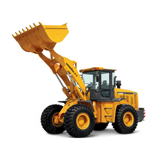
- Page 66 2.3 PURPOSE PURPOSE PURPOSE CDM853 articulated wheel loader is a medium- and small-sized, efficient and multi- functional earthmoving machine and mainly used for handling bulk materials. The loader is widely used for loading, bulldozing, shoveling, traction, lifting and transportation in mines, civil works, road constructions, harbors and goods yards.
- Page 67 CHAPTER CHAPTER CHAPTER III III III III OPERATION OPERATION OPERATION INSTRUCTIONS INSTRUCTIONS CHAPTER OPERATION INSTRUCTIONS INSTRUCTIONS STEERING WHEEL 3.1STEERING STEERING STEERING WHEEL WHEEL WHEEL The articulated loader uses fully hydraulic power steering. The steering wheel is arranged inside the Cab and connected to the full-hydraulic redirector. Turning clockwise the steering wheel turns the loader right;...
- Page 68 witch handle counterclockwise to “OFF” position. To turn turn turn turn on on battery battery battery battery negative negative negative negative pole pole pole pole switch: switch: switch: switch: Before starting the loader, it is necessary to turn the negative-pole switch handle clockwise to “ON”...
- Page 69 START START START START--Insert and clockwise turn the starter switch, the second position is “START”. With the key at “START” position, the motor is energized to start the engine. Immediately release the key after the engine has been started, the key will automatically return to “ON”...
- Page 70 The accelerator pedal is arranged on the right front floor of Cab. Not depressing the accelerator pedal, the engine will stay at the idle status. Depressing the accelerator pedal will increase the fuel supply to diesel engine thus the output power of diesel engine.
- Page 71 front and rear movements of joystick are used to control the moving direction of the lift arm. Both joysticks are normally in a middle position. When the engine is working, by pushing forwards the pilot joystick, the lift arm will be lowered; by pulling backwards the pilot joystick, the lift arm will be raised;...
- Page 72 LAMPS THEIR SWITCHES 3.8 LAMPS LAMPS LAMPS AND AND THEIR THEIR THEIR SWITCHES SWITCHES SWITCHES The lamps of loader include front combination lamps (left, right), front working lamps (left, right), rear working lamps (left, right), rear combination lamps (left, right), in-cab lamp, and alarm lamp.
- Page 73 In-cab lamp Warning lamp Rocker Rocker Rocker Rocker switch switch switch switch assembly assembly assembly assembly (below steering wheel) 1. Combination lamp switch: The combination lamp switch controls the ON and OFF state of the combination lamp. 2. Front working lamp switch: The front working lamp controls the ON and OFF state of the front working lamp.
- Page 74 Each rocker switch has a switch indicator lamp. When the combination switch is closed, the switch indicator lamp is lit up; when the combination switch is open, the switch indicator lamp is not lit up. Warning Warning Warning Warning Check Check Check if if if if brake brake...
- Page 75 3.9INSTRUMENT INSTRUMENT INSTRUMENT INSTRUMENT ASSEMBLY ASSEMBLY ASSEMBLY ASSEMBLY AND AND HORN HORN HORN HORN SWITCH SWITCH SWITCH SWITCH All monitoring instruments, warning system and steering indicating system of the loader are integrated into the instrument assembly that is below the steering wheel. The instrument system displays many items: engine water temperature, engine oil pressure, engine speed, brake air pressure, fuel amount, transmission oil temperature, system voltage, battery charging indicator, low brake pressure alarm, low transmission oil...
- Page 76 the loader loader loader loader in in in in a a a a place place place place safe safe safe safe and and suitable suitable suitable suitable for for repair repair repair repair work work work work and and shut shut shut shut down...
- Page 77 move move loader loader until until failure failure been been resolved! resolved! move move the the loader loader until until the the failure failure has has been been resolved! resolved! 3.9.2 3.9.2 3.9.2 3.9.2 HORN HORN HORN HORN SWITCH SWITCH SWITCH SWITCH The horn switch is arranged at the center of...
- Page 78 The engine coolant absorbs engine heat and flows through the evaporator of air conditioning system, and the evaporator then disperses the heat, that’s how the air conditioning system perform the heating function. Two manual warm water valves are mounted to the water inlet and outlet of evaporator, respectivel Warm Warm...
- Page 79 Adjustment Adjustment Adjustment to to to to backrest backrest backrest angle angle Adjustment backrest angle angle A handle is provided in the lower left portion of seat. Turning clockwise the handle can press the backrest forward or backward to expected position.
- Page 80 anchorage will lock the buckle. Press the red button near the anchorage, the buckle will spring out. Before using the safety belt, inspect the anchorage. 3.13 3.13 DOOR DOOR LOCK LOCK 3.13 3.13 CAB CAB DOOR DOOR LOCK LOCK The keys to the right and left doors of Cab are the same. If the door is locked, the core of lock cannot be pressed down with the thumb.
- Page 81 3.15 ADJUSTMENT REAR-VIEW MIRROR 3.15 3.15 3.15 ADJUSTMENT ADJUSTMENT ADJUSTMENT TO TO REAR-VIEW REAR-VIEW REAR-VIEW MIRROR MIRROR MIRROR A rear-view mirror is installed on the left and right front of Cab top, respectively. Adjust the rear-view mirrors to correct positions before operating the loader. To adjust the position of rear-view mirror, loosen the bolt that fastens the rear-view mirror support to the Cab, and then rotate the support.
- Page 82 3.18 3.18 SUNSHADE SUNSHADE 3.18 3.18 SUNSHADE SUNSHADE 1. Pull the handle lever in the middle by hand to unroll the sunshade cloth. Pull to an appropriate position and release the lever, and the sunshade will stop at that position; if the position is not appropriate, continue to pull the lever to the maximum position of travel.
- Page 83 s (in the present wave band, select radio stations cyclically; press the AMS/BND button to switch to the other wave band.) 3. 3. 3. 3. Mode Mode Mode Mode conversion/mute conversion/mute conversion/mute conversion/mute button button button button (MOD/MUT) (MOD/MUT) (MOD/MUT) (MOD/MUT) In the starting state, press the button long to conduct mode conversion: radio –...
- Page 84 1.LCD screen 2. Power switch/pause/radio 3. Mode conversion/mute station selection button button 4. Volume up/forward 5. Volume down/backward 6. Clock button selection/forward search selection/backward search button button 7. Waveband/automatic 8. U-disk socket 9.SD/MMC card socket station saving button 10. Decorative knob...
- Page 85 CHAPTER CHAPTER CHAPTER IV IV IV IV OPERATION OPERATION OPERATION CHAPTER OPERATION NOTICES OPERATION LOADER 4.1NOTICES NOTICES NOTICES ON ON OPERATION OPERATION OPERATION OF OF NW NW LOADER LOADER LOADER Even though each loader is properly inspected and adjusted before leaving the factory, it is still necessary to abide by the following procedures during the running-in period, otherwise the loader may get damaged or its performance may be reduced.
- Page 86 RUNNING-IN RUNNING-IN LOADER LOADER 4.2RUNNING-IN RUNNING-IN OF OF NEW NEW LOADER LOADER For a new loader, the running-in will play an important role in prolonging the service life of the loader, eliminating hidden faults and avoiding the occurrence of serious fault. The user shall carry out operation and maintenance in accordance with the provisions relating to running-in of new loader as specified in this Manual after purchasing the loader, and then the loader may be used normally.
- Page 87 Inspect the temperature and connection of each part of electrical systems, the power supply to engine, the conditions and lightening devices and turn lamps. NOTE: NOTE: when when inspecting inspecting level level level of of of of any oil or or or or fluid, fluid, fluid, sure...
- Page 88 Figure: Inspect the wiring of battery. Connect the wiring according to the figure. 4.3.2 4.3.2 STARTUP STARTUP ENGINE ENGINE 4.3.2 4.3.2 STARTUP STARTUP OF OF ENGINE ENGINE Clear away the persons around the loader and the obstacles in the travelling direction of the loader;...
- Page 89 switch, switch, wait wait wait at at at at least least least seconds seconds then then attempts attempts attempts to to to to start start start engine engine again. again. switch, switch, wait least 30 30 seconds seconds and and then then attempts start up up the...
- Page 90 2. Step down the service brake pedal, rotate the handle brake button to reset it, slowly let go of the service brake pedal, and observe whether the loader moves. WARNING: WARNING: WARNING: If If If If the loader loader moves, moves, immediately immediately...
- Page 91 6. In case there is a corner ahead, please operate the loader in accordance with the local laws and regulations relating to traffic. When the loader is about to turn, pull or push the turn lamp handle in the corresponding direction.
- Page 92 4.3.4 PARKING LOADER 4.3.4 4.3.4 4.3.4 PARKING PARKING PARKING OF OF LOADER LOADER LOADER • Drive the loader to a flat place which is free from the risk of falling stone, landslide or flood. Apply the service brake to stop the loader. •...
- Page 93 3) Pull the gear-shifting lever to the neutral position. 4) Rotate the parking brake button to reset it and apply the parking braking. 5) Place the bucket on the ground horizontally, and pull the pilot joystick to the middle position. 6) Set each switch at the middle position or off position, and then lock up all doors.
- Page 94 4.4 WORKING WORKING WORKING WORKING OF OF LOADER LOADER LOADER LOADER 4.4.1 4.4.1 4.4.1 4.4.1 PREPARATION PREPARATION PREPARATION PREPARATION BEFORE BEFORE BEFORE BEFORE WORKING WORKING WORKING WORKING Before the commencement of the working, use the loader to flatten the working place, �...
- Page 95 any more after being inserted into the material pile, just pull backwards the joystick with your right hand and then push it to the middle position, so as to lift up the bucket for once. In this way, the bucket may go ahead for certain distance. Thereafter, push forwards the pilot joystick and then push it to the middle position, so as to turn backwards the bucket for once.
- Page 96 ① Discharging of materials into truck or hopper When the loader which is loaded with materials is 15 meters away from the truck or � hopper, just release the accelerator pedal, and if necessary, intermittently apply the service brake, so as to slow down the loader and make the loader approaches the truck or hopper at a low speed.
- Page 97 Push-transportation Push-transportation Push-transportation Push-transportation Place the bucket horizontally close to the ground, set the gear-shifting level at the � position of forward gear 1, and then push down the accelerator pedal, so as to make the loader move forwards. If an obstacle is found in the course of working, just slightly raise the lift arm and go ahead.
- Page 98 The total height, total width and total weight after the loader is placed on the transportation vehicle may not exceed the specified value. If the height or width exceeds the specified value, please consult with LONKING Holdings Limited or its distributor for solution.
- Page 99 Figure: Use Chock to Block up the Wheels of the Towing Tractor 2. After the loader has driven onto the towing tractor or truck, no turning operation may be carried out in the course of transportation. If it is necessary to carry out turning operation, please carry out the operation only after the loader has returned to flat ground.
- Page 100 have the hoisting-related knowledge. 2. Please calculate the maximum hoisting weight of crane and the loading capacity of sling (the weight of loader is 12300±300 kg), so as to ensure the safety. In addition, please ensure that the four hooks on the sling will be under even stress. 3.
- Page 101 If the loader in trouble is towed on a bad road, it will further damaged. If the brake system fails, the brake is out of use, and special attention shall be paid in the course of towing operation. Precautions for towing operation: 1.
- Page 102 2) To tow the loader with the engine switched off If the engine fails, please tow the loader in accordance with the following method. If the service brake system and parking brake system is properly sealed with no leakage, the pressure oil in the energy accumulator may be used to release parking brake. In this case, the pressure oil in the energy accumulator can only be used for 6~7 times.
- Page 103 Be sure not to use any anti-freezing fluid which contains methanol, ethanol or • propanol. Be sure not to use any anti-leakage agent, no matter it is used alone or together with • anti-freezing fluid. Be sure not to mix up anti-freezing fluids of different designation. •...
- Page 104 If no permanent anti-freezing fluid is used, be sure to fully drain the water in the cooling system, clean up the cooling system, and then fill the new coolant. OPERATION UNDER SPECIAL CONDITIONS 4.7OPERATION OPERATION OPERATION UNDER UNDER UNDER SPECIAL SPECIAL SPECIAL CONDITIONS CONDITIONS...
- Page 105 ground. 4.7.2 OPERATION UNDER EXTREMELY WEATHER 4.7.2 4.7.2 4.7.2 OPERATION OPERATION OPERATION UNDER UNDER UNDER EXTREMELY EXTREMELY EXTREMELY HOT HOT WEATHER WEATHER WEATHER The continuous operation at high temperature may get the loader overheated. If necessary, monitor the temperature of engine and gearbox, and stop the loader so as to cool them down.
- Page 106 ③ Apply the anti-corrosion lubricating oil onto the unpainted or exposed surfaces. Use insulating compound to protect wires and terminates. On the damaged surfaces, use paint or appropriate antirust agent to prevent rust or corrosion. 4.7.3 4.7.3 PERATION PERATION PERATION IN IN IN IN DUSTY DUSTY DUSTY SANDY...
- Page 107 3. Repair the damaged paint in time. 4. Lubricate the loader in accordance with the lubrication sign and lubrication interval table on the loader. As for the loader working in salt water, the lubrication interval shall be shortened appropriately. 4.7.6 OPERATION HIGH ALTITUDE...
- Page 108 CHAPTER CHAPTER CHAPTER V V V V MAINTENANCE MAINTENANCE MAINTENANCE REPAIR REPAIR CHAPTER MAINTENANCE AND AND REPAIR REPAIR PREPARATION BEFORE MAINTENANCE 5.1PREPARATION PREPARATION PREPARATION BEFORE BEFORE BEFORE MAINTENANCE MAINTENANCE MAINTENANCE Follow Follow with with "Maintenance "Maintenance Security Security Matters" Matters" mentioned mentioned mentioned in in in in the...
- Page 109 Check the oil level of the transmission to ensure that the level stays within the normal operating range, add it as necessary. Check the fuel whether it is enough or not, add it if necessary. Check the air filter of engine whether it is clean or not, replace it if necessary. Drain all air reservoirs for pneumatic brake machines;...
- Page 110 III. III. III. III. Maintenance Maintenance Maintenance Maintenance items items items items to to to to be be performed performed performed performed once once once once every every every every 100 100 hours hours hours hours or or or or every every every every half...
- Page 111 e main drive in the center of the axle housing; replace all the drive axle gear oil once each year even if the total number of work hours is less than 500. Maintenance Maintenance items items items to to to to be performed performed once...
- Page 112 Attachment Attachment Attachment Attachment 1 1 1 1 Machine No.: Registration Registration Registration Registration Table Table Table Table for for Phase-by-phase Phase-by-phase Phase-by-phase Phase-by-phase Checking Checking Checking Checking and and Maintenance Maintenance Maintenance Maintenance of of of of the the Loader Loader Loader Loader...
- Page 113 Attachment Attachment Attachment Attachment 1 1 1 1 Machine No.: Registration Registration Registration Registration Table Table Table Table for for Phase-by-phase Phase-by-phase Phase-by-phase Phase-by-phase Checking Checking Checking Checking and and Maintenance Maintenance Maintenance Maintenance of of of of the the Loader Loader Loader Loader...
- Page 114 Attachment Attachment Attachment Attachment 1 1 1 1 Machine No.: Registration Registration Registration Registration Table Table Table Table for for Phase-by-phase Phase-by-phase Phase-by-phase Phase-by-phase Checking Checking Checking Checking and and Maintenance Maintenance Maintenance Maintenance of of of of the the Loader Loader Loader Loader...
- Page 115 Attachment Attachment Attachment Attachment 1 1 1 1 Machine No.: Registration Registration Registration Registration Table Table Table Table for for Phase-by-phase Phase-by-phase Phase-by-phase Phase-by-phase Checking Checking Checking Checking and and Maintenance Maintenance Maintenance Maintenance of of of of the Loader(No.4) Loader(No.4) Loader(No.4) Loader(No.4)
- Page 116 Attachment Attachment Attachment Attachment 1 1 1 1 Machine No.: Registration Registration Registration Registration Table Table Table Table for for Phase-by-phase Phase-by-phase Phase-by-phase Phase-by-phase Checking Checking Checking Checking and and Maintenance Maintenance Maintenance Maintenance of of of of the the Loader Loader Loader Loader...
- Page 117 LUBRICATION CHART 5.3 LUBRICATION LUBRICATION LUBRICATION CHART CHART CHART Grease the lubricant at various sliding bearing or rolling bearing sections, such as: Driving shaft with cross head. All pin sets at both ends of the tanks. Hinge pin sets of front and rear frame; sub-frame swing the pin sets. Each pin sets of the working device Inject grease into the above mentioned sections with pressure.
- Page 119 5.4 THE THE CHINESE CHINESE CHINESE CHINESE AND AND FOREIGN FOREIGN FOREIGN FOREIGN OIL OIL TYPE TYPE TYPE TYPE LIST LIST LIST LIST FOR FOR WHEEL WHEEL WHEEL WHEEL LOADER LOADER LOADER LOADER Oil Name Chinese standard serial number and type International standard serial number and type Ordinary CD 15W/40 Ordinary CF-4 15W/40...
- Page 120 JARNC-4 which was developed by Xi'an Petroleum University Jiarun Industry and PTF-3 PTF-2 have the same quality 1.John-Deer company's J-20B,J-14B,JDT-303 6#(n32)= PTF-2 2.Ford company's M2C41A,MIC86A,MIC134A 8#(n46)= PTF-1 3.Massay-Ferguson company's M-1135,M-1127A N68#(Anti-wear hydrodynamic transmission oils)= PTF-3 OrdinaryAPI GL-5 SAE90 OrdinaryLS-90 (RecommendMobilGX90) Gear Oil Low temperature LowtemperatureAPI GL-5 SAE80W-90...
- Page 121 INFORMATION INFORMATION 5.5 OIL OIL INFORMATION INFORMATION In the large scale of -30 to 50 Celsius, grade, provision and addition in each small range for the recommended engine oil, transmission oil, hydraulic oil, drive axle oil, pin shaft lubrication grease, diesel oil, antifreeze.(with international grade and metric unit).
- Page 122 UNIVERSAL UNIVERSAL TORQUE TORQUE TABLE TABLE 5.6UNIVERSAL UNIVERSAL TORQUE TORQUE TABLE TABLE Unless otherwise stated, the screw used in the machines should be tightened according to the following table. Universal torque table of metric thread Tightening torque (N.M) Specifications 8.8 class 10.9 class 9~12 13~16...
- Page 123 The coolant of the engine is composed and with water, antifreeze liquid and additives in certain proportion. LONKING recommends using the mixture of 50% ethylene glycol or propylene glycol- based antifreeze and 50% soft water as the coolant of the engine in most weather conditions.
- Page 124 The anti-rust agent can delay or prevent the engine water jacket wall and the radiator from rusting or corrosion. The air in the coolant will produce a lot of bubbles under the stirring of the blades of the water pump, these bubbles will hinder the cooling water jacket wall from heat radiating.
- Page 125 In fact, the volume of antifreeze of the cooling system requires is about 45L or so (to be confirmed that the coolant in the previous cooling system, including heating section of the air- conditioning system has been exhausted). Manually switch on the negative pole switch of battery, and insert the key into a starter Warm water valve switch and rotate in clockwise direction to...
- Page 126 Heat radiator is located at the tail of the machine. Water inlet of heat radiator, see right figure: 1. Slowly uncap the pressure cap at the upper section of the heat radiator, and gradually release the pressure. Warning Warning Warning Warning Under Under...
- Page 127 Warning Warning Warning Warning As the the engine engine engine engine coolant coolant coolant coolant is is is is toxic, toxic, toxic, toxic, do do not not drink drink drink drink or or or or casually casually casually casually discard. discard.
- Page 128 Set pressure drop alarm indicator connector at the outlet of the air filter, the yellow piston of the air filter indicator moves to the red area when the engine is running in high idle speed. The air filter needs maintenance. Air filter alarm indicator is shown in the right figure: Shut down the engine, and remove the air...
- Page 129 Remove coarse filter. 4. Remove fine filter. 5. Blow away the dust on the filter paper of coarse filter with compressed air free of oil mist, water (pressure less than 300KPa). (After coarse filter is cleaned five times, it is needed to replace air fine filter and cleaned fine filter shall not be used again.) 6.
- Page 130 found over it or gasket or seal is damaged, replace it with a new coarse filter. 7. Install the clean coarse filter into the air filter shell to ensure the even contact of the sealing part at the end of the coarse filter. 8.
- Page 131 5.8.2 5.8.2 FUEL FUEL LEVEL LEVEL INSPECTION INSPECTION 5.8.2 5.8.2 FUEL FUEL OIL OIL LEVEL LEVEL INSPECTION INSPECTION Drive the loader to the even site, turn off the engine. Turn the key clockwise and switch to shift one, and power on the whole car. Inspect the amount of instruments on stage fuel table instructions.
- Page 132 the engine, and then install it to the install seat. 5.8.5 MAINTENANCE ENGINE 5.8.5 5.8.5 5.8.5 MAINTENANCE MAINTENANCE MAINTENANCE OF OF ENGINE ENGINE ENGINE OIL Inspect the oil level of engine oil 1. Park the loader to even field, turn off engine and rotate the parking brake button to reset.
- Page 133 oil pan, and re-check the oil level, if the oil is in shortage, please refill the oil until the oil falls between “L" and "H" level of the foot scale. Warning Warning Warning Warning Change Change Change Change the the oil oil filter filter filter...
- Page 134 melt the battery electrolyte prior to starting, and inspect whether there is any leakage. 2. Inspect the battery shell Do not add more power if the battery case cracks or leaking battery acid, identify the reason then replace the battery. 3.
- Page 135 1) After the machine is powered on, inspect whether instrument indications are normal; In case of any failure, first inspect whether the sensors are damaged or not; in case of no damage, inspect the corresponding temperatures in the following table to confirm whether the resistances meet the requirements in the table below.
- Page 136 When perform soldering on the whole machine, follow the following regulations to avoid damage to machinery and security incidents. Before soldering, shut down the engine, unplug the key switch, turn off the negative pole switch of battery; Before soldering, must remove the wiring harness connectors of the dashboard to avoid damage to instrument;...
- Page 137 Refueling port of the gearbox is at the left side of the frame articulated section; please inspect the oil level of the gearbox regularly according to the regulated cycle. Gearbox may be damaged if its oil level is too high or too low. Please keep transmission oil level in the correct position.
- Page 138 7. Refuel the clean transmission oil from the oil filling pipe of the gearbox, and inspect the oil level of gearbox according to the above method, and fill to the regulated oil level. Before replacing transmission oil, cover the parking brake well to prevent the friction plate of parking brake from oil and reduce the brake performance.
- Page 139 Drive the machine to park at a flat ground; slowly move the car with low oil supplying, to keep the oil outlet screw piston at the end side of the wheel rim of the front drive axle to be located at the lowest position. As the oil outlet screw pistons at the end side of the wheel rim of the front drive axle cannot be located at the lowest position at the same time, therefore, the front and rear drive axles should replace oil twice.
- Page 140 should be followed with: 1. The machine should be stored in dry room. If the car has to be parked in the open air, it should be stopped on the concrete ground for easy drainage of water, and cover it with canvas.
- Page 141 The maintenance for the operation in rocky environment, Inspect the wheel and tire assembly to confirm whether there is any damages or excessive wear and tear. Inspect joints and fasteners to confirm they are loose or damaged. More frequently inspect the bucket or breaker to confirm whether they are damaged or excessively worn.
- Page 142 actions, actions, actions, actions, please please please please note note note note to to to to perform perform perform perform in in in in accordance accordance accordance accordance with with with with the the relevant relevant relevant relevant safety safety safety safety regulations.
- Page 143 If If If If the hydraulic hydraulic been been seriously seriously polluted, polluted, polluted, in in in in addition addition addition addition to to to to drain drain drain the hydraulic hydraulic oil oil has has been been seriously seriously polluted, drain out out the hydraulic...
- Page 144 Find out the lift arm pin hole and bucket pin hole, to install the bucket pin (2, Figure 4). Lock the Pin Plate bolts of Bucket (1, Figure 2). Figure 4...
- Page 145 CHAPTER CHAPTER CHAPTER VI VI VI VI COMMON COMMON COMMON FAULTS FAULTS TROUBLE- TROUBLE- CHAPTER COMMON FAULTS FAULTS AND AND TROUBLE- TROUBLE- SHOOTING SHOOTING SHOOTING SHOOTING Fault Fault Cause Cause Action Action Fault Fault Cause Cause Action Action Switch for gearing again, or re-adjust the Shift is not geared on.
- Page 146 Fault Fault Fault Fault Cause Cause Cause Cause Action Action Action Action Loss flow of steering pump is inadequate. Inspect or replace the steering pump Pressure change of the safety pressure Steering torque is Adjust its pressure (pressure) valve insufficient Steering pump leaks seriously inside.
- Page 147 Fault Fault Cause Cause Action Action Fault Fault Cause Cause Action Action The charging pressure of energy Check the air pressure of energy Filling frequency of accumulator is wrongly set. accumulator. filling valve is too high. Filling valve does not work. Replace the filling valve.
- Page 148 Fault Fault Fault Fault Possible Possible Possible Possible cause cause cause cause Fault Fault Fault Fault phenomenon phenomenon phenomenon phenomenon Elimination Elimination Elimination Elimination method method method method Identify other causes Refrigerant leak in the system No pressure indication Refill with refrigerant Electrical devices (compressor/evaporating Normal pressure indication...
- Page 149 Fault feature Cause Elimination method Fault Fault Fault feature feature feature Cause Cause Cause Elimination Elimination Elimination method method method Reverse polarity connection of power Connect to power source source Power lamp of MP3 player is not lit up Disconnected protective tube or open Check and connect power line correctly, replace power line protective tube...
- Page 151 CHAPTER CHAPTER MAINTENANCE MAINTENANCE SERVICING SERVICING CHAPTER CHAPTER VII VII MAINTENANCE MAINTENANCE AND AND SERVICING SERVICING OF AIR-CONDITIONING AIR-CONDITIONING SYSTEM SYSTEM AIR-CONDITIONING AIR-CONDITIONING SYSTEM SYSTEM Item Item Item Item Content Content Content Content Whether air blower operates with abnormal noise Evaporator Whether air inlet &...
- Page 152 CHAPTER CHAPTER VIII VIII ENVIRONMENTAL ENVIRONMENTAL PROTECTION PROTECTION CHAPTER CHAPTER VIII VIII ENVIRONMENTAL ENVIRONMENTAL PROTECTION PROTECTION REQUIREMENT REQUIREMENT REQUIREMENT REQUIREMENT When performing maintenance, the parts replaced should not be arbitrarily discarded, and should be recycled. When performing maintenance, do not put coolant, oil (fuel, engine oil, hydraulic oil, transmission oil, gear oil, grease, etc.), electrolyte or other objects may cause environmental pollution, directly on the ground, use the special containers to collect them and dispose them in accordance with relevant regulations.
- Page 153 APPENDIX: APPENDIX: REFERENCE REFERENCE TABLE TABLE PROPORTION PROPORTION APPENDIX: APPENDIX: REFERENCE REFERENCE TABLE TABLE OF OF PROPORTION PROPORTION OF COMMON COMMON MATERIALS MATERIALS COMMON COMMON MATERIALS MATERIALS Specific Specific Specific Specific gravity gravity gravity gravity reference reference reference reference Material Material name name...
Need help?
Do you have a question about the CDM853 and is the answer not in the manual?
Questions and answers