Advertisement
Quick Links
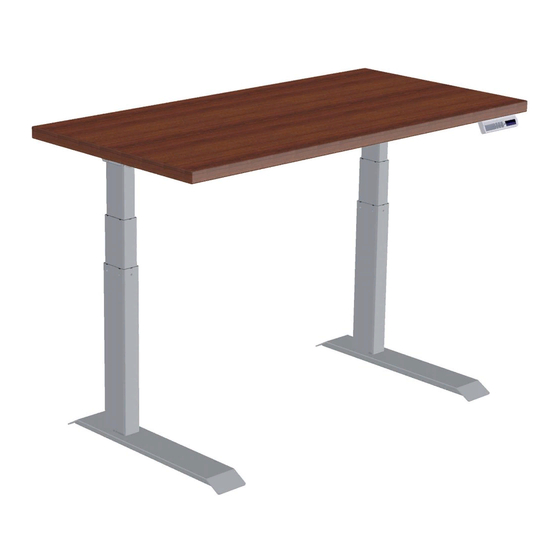
Assembly & Installation Instructions:
Fundamentals 2-Leg Workcenter FDEX54-72-X / FDLX54-72-X
Parts Included
A
Master Leg
Qty: 1
B
Companion Leg
Qty: 1
C
Short Bracket
Qty: 2
D
Left End Bracket
Qty: 1
E
Right End Bracket
Qty: 1
F
4 mm Allen Wrench
Qty: 1
1 of 7
G
#M6 × 14 mm Flat Head Cap
Screw
Qty: 20
H
Foot Glide
Qty: 4
I
#12 × ¾" Pan Head Laminate
Top Screw
Qty: 26
J
Power Supply
Qty: 1
K
Cable Spool
Qty: 1
L
#8 × ⅝" Pan Head Screw
Qty: 7
M
3/ 1 6" Cable Loops
Qty: 5
N
Leg Cable - 2 meter
Qty: 1
O
Power Cable - 3.5 meters
Qty: 1
P
Feet
Qty: 2
Q
Standard or
Programmable Switch
Qty: 1
R
Long Bracket
Qty: 2
Sold Separately:
Worksurface
Workrite Ergonomics | 800.959.9675 www.workriteergo.com
or
Advertisement

Subscribe to Our Youtube Channel
Related Manuals for Workrite Ergonomics FDEX54-72-X

Summary of Contents for Workrite Ergonomics FDEX54-72-X
- Page 1 Assembly & Installation Instructions: Fundamentals 2-Leg Workcenter FDEX54-72-X / FDLX54-72-X Parts Included Master Leg #M6 × 14 mm Flat Head Cap Power Cable - 3.5 meters Qty: 1 Screw Qty: 1 Qty: 20 Foot Glide Feet Qty: 4 Qty: 2...
- Page 2 Loading should be evenly distributed over table surfaces. “Payload Capacity” is the Workrite Ergonomics recommended maximum loading which includes the Workrite sourced table top.
- Page 3 Note: the right leg will be on your left and vice versa when the assembly is seen upside down. Right (Master) leg front Left (Companion) leg Hardware at actual size #M6 × 14 mm Flat Head Cap Screw 3 of 7 Workrite Ergonomics | 800.959.9675 www.workriteergo.com...
- Page 4 3.3 Tighten first six (6) screws securely. Do not drill all the way through worksurface! Hardware at actual size #12 × ¾" Pan Head Laminate Top Screw 4 of 7 Workrite Ergonomics | 800.959.9675 www.workriteergo.com...
- Page 5 6.1 Attach Cable Spool (K) with the #12 × ¾"Pan Head Laminate Top Screw (I) to underside of worksurface. 6.2 Attach Cable Loops (M) to underside of worksurface using the #8 × ⅝” Pan Head Screw (L) making sure to wrap the Cable Loop around the cable prior to attaching. 5 of 7 Workrite Ergonomics | 800.959.9675 www.workriteergo.com...
- Page 6 Never connect or remove leg or 8.2 Turn the table over into an upright position. control cables when power is connected! Doing so will damage the Master Leg. 8.3 Plug the Power Cord into the power outlet. 6 of 7 Workrite Ergonomics | 800.959.9675 www.workriteergo.com...
- Page 7 To clean the legs, apply cleaner to a soft cloth. Suggested cleaners: Windex or Formula 409. Do not use solvents and do not saturate or spray cleaners directly to table base. 7 of 7 Workrite Ergonomics | 800.959.9675 www.workriteergo.com #1500443- Rev B...
Need help?
Do you have a question about the FDEX54-72-X and is the answer not in the manual?
Questions and answers