
Related Manuals for VIPA 606-3B4E1


Summary of Contents for VIPA 606-3B4E1
- Page 1 VIPA HMI Touch Panel | 606-3B4E1 | Manual HB160E_TP | RE_606-3B4E1 | Rev. 11/07 February 2011...
- Page 2 Copyright © VIPA GmbH. All Rights Reserved. This document contains proprietary information of VIPA and is not to be disclosed or used except in accordance with applicable agreements. This material is protected by the copyright laws. It may not be reproduced, distributed, or altered in any fashion by any entity (either internal or external to VIPA), except in accordance with applicable agreements, contracts or licensing, without the express written consent of VIPA and the business management owner of the material.
- Page 3 Manual VIPA System HMI Contents Contents About this manual ..................1 Safety information ..................2 Chapter 1 Hardware description ............. 1-1 Safety information for Users..............1-2 Properties..................... 1-3 Structure ....................1-4 Components..................1-6 Dimensions ..................1-10 Technical Data ................... 1-11 Chapter 2 Deployment Touch Panel ..........
- Page 4 Contents Manual VIPA System HMI HB160E - TP - RE_606-3B4E1 - Rev. 11/07...
- Page 5 About this manual About this Manual The manual describes the Touch Panel TP 606C from VIPA. Here you find detailed descriptions of the Touch Panel beside a product overview. Here you get information about structure, project engineering and operation of the Touch panels from VIPA.
- Page 6 About this manual Manual VIPA System HMI Objective and This manual describes the Touch Panels from VIPA. The manual consists of chapters. Every chapter provides the description of one specific topic. contents It describes the installation, project engineering, usage and the technical data.
- Page 7 Safety information Safety information The Touch Panels are constructed and manufactured for: Applications conforming with • VIPA CPUs 11x, 21x, 31x, 51x and S7-300/400 from Siemens specifications • communication and process control • general control and automation applications • industrial applications •...
- Page 8 Safety information Manual VIPA System HMI HB160E - TP - RE_606-3B4E1 - Rev. 11/07...
- Page 9 During this chapter you get hints for deployment of the Touch Panel Overview TP 606C from VIPA. Besides of a description of the single components of the Touch Panel, you will also find the dimensions that are required for the installation. The chapter closes with the technical data.
- Page 10 Chapter 1 Hardware description Manual VIPA HMI Safety information for Users VIPA modules make use of highly integrated components in MOS- Handling of technology. These components are extremely sensitive to over-voltages electrostatic that can occur during electrostatic discharges. sensitive modules...
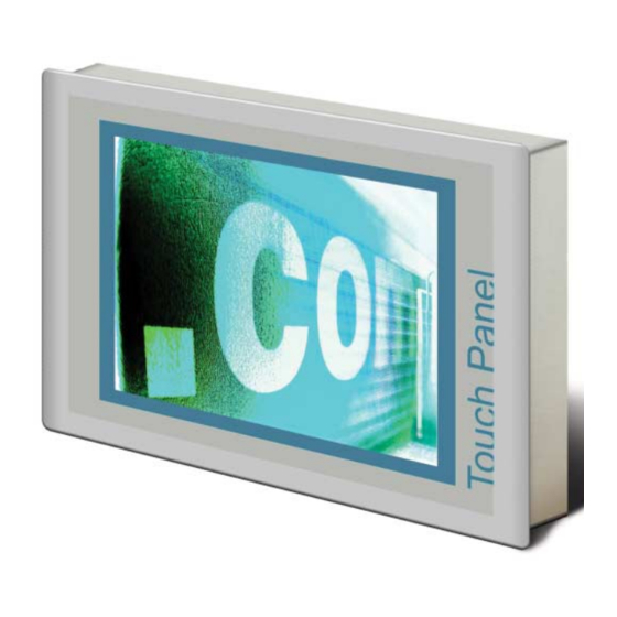
- Page 11 Chapter 1 Hardware description Properties The Touch Panel allows you to visualize and alter operating states and General recent process values of a connected PLC. The VIPA Touch Panel is a compact and modular embedded PC based on TP 606C ® ® 606-3B4E1 Windows CE.
- Page 12 [3] Display with touch sensitive area (touch screen) Side view [1] Compact Flash [2] MMC / SD Note! Please only use storage media, which are tested and approved by VIPA GmbH. HB160E - TP - RE_606-3B4E1 - Rev. 11/07...
- Page 13 Manual VIPA HMI Chapter 1 Hardware description Bottom view (Interfaces) TP 606C 6.5'' 606-3B4E1 RS422/485 interface COM 2 Components RS232 interface COM 1 MPI/PROFIBUS DP/RS485 interface "Host"-USB-A interface "Slave"-USB-B interface RJ45 jack for Ethernet communication Slot for DC 24V voltage supply...
- Page 14 Chapter 1 Hardware description Manual VIPA HMI Components The following memory systems are available for every Touch Panel: Memory management • 128Mbyte work memory • 2Gbyte Micro-SD card (ca. 1800Mbyte for user data) • USB storage media using "Host"-USB-A interface •...
- Page 15 Manual VIPA HMI Chapter 1 Hardware description • Logical states represented by voltage differences between the 4 cores RS422/485 • Serial bus connection in 4-wire technology using full duplex mode interface • Data communications up to a max. distance of 500m •...
- Page 16 Chapter 1 Hardware description Manual VIPA HMI • Interface is compatible to the COM interface of a PC RS232 interface • Logical signals as voltage levels • Point-to-point links with serial full-duplex transfer in two-wire technology up to 15m distance •...
- Page 17 The USB-A interface of your PC can be connected to the "Slave"-USB-B Programming cable interface of your Touch Panel deploying the USB programming cable. The USB programming cable is delivered by VIPA with order No. VIPA 670-0KB10. The Touch Panel has got an integrated power supply. The power supply Power supply has to be provided with DC 24V (20.4 ...
- Page 18 Chapter 1 Hardware description Manual VIPA HMI Dimensions installation width width installation depth For the installation of the Touch Panel in control cabinets and desks the Installation following dimensions are necessary: dimensions 6.5'' Front panel width 2.5 ... 6mm 606-3B4E1...
- Page 19 Manual VIPA HMI Chapter 1 Hardware description Technical Data Order number 606-3B4E1 Type Touch Panel TP 606C Display Display size (diagonal) 6.5 " Display size (width) 132.5 mm Display size (height) 99.4 mm Resolution 480 x 640 / 640 x 480...
- Page 20 Chapter 1 Hardware description Manual VIPA HMI Order number 606-3B4E1 Mounting via integrated pivoted lever Protect type front side IP 65 Protect type back side IP 20 Dimensions Front panel 212 x 156 x 7.5 mm Rear panel 198 x 142 x 37 mm...
-
Page 21: Table Of Contents
Manual VIPA HMI Chapter 2 Deployment Touch Panel Chapter 2 Deployment Touch Panel This chapter deals with the employment of the Touch Panel. Overview At the start of the chapter you receive information about the assembly and the connection of the Touch Panel. The main part of the chapter introduces ®... -
Page 22: Installation
Chapter 2 Deployment Touch Panel Manual VIPA HMI Installation The Touch Panel is suitable for the installation in operating tables and Overview control cabinet fronts. The installation happens via the backside. The Touch Panel is provided with a patented integrated fixing technique that allows an easy connection with a simple screwdriver. - Page 23 Manual VIPA HMI Chapter 2 Deployment Touch Panel Connect For the cabling of the DC 24V power supply green plugs with CageClamp technology are deployed. The spring-clip connector technology simplifies power supply the wiring requirements for signaling and power cables. In contrast to screw terminal connections, spring-clip wiring is vibration proof.
-
Page 24: Commissioning
As soon as the Touch Panel is provided by power supply the Touch Panel VIPA Startup starts with "user area" of the VIPA Startup Manager: Manager User area On delivery the button [Advanced] is shown at the starting screen. Further... - Page 25 Here the communication interfaces may also be configured. Further you reach here the TP information: product number, serial number and licenses. Exit The VIPA Startup Manager is closed by [Exit] and the system returns to the ® Windows operating system.
- Page 26 Chapter 2 Deployment Touch Panel Manual VIPA HMI Settings Buttons may be configured with [Settings]. Here buttons may be added or removed respectively assigned with programs. Main Here general settings may be established. A new background picture may be loaded at "Background ...". With "Font Color"...
- Page 27 Manual VIPA HMI Chapter 2 Deployment Touch Panel Fixed Here the buttons are listed, which may not be changed in the user respectively administrator area. Custom Here new buttons may be configured and assigned with corresponding programs. You may choose "Normal" for the user area or "Advanced" for the administrator area.
- Page 28 Chapter 2 Deployment Touch Panel Manual VIPA HMI Password The administrator area may be protected by a password. Here you may enter respectively change the password of the administrator area. If you click within the user area to the button [Advanced] and a password is defined, you were prompted to enter the password.
- Page 29 Manual VIPA HMI Chapter 2 Deployment Touch Panel Execute Here programs may be added, which have to start in the background during startup e.g. VNC server or transport services. With enabling the checkbox "Autostart" the program is always executed on startup after the preset "Delay time".
- Page 30 Chapter 2 Deployment Touch Panel Manual VIPA HMI About Here you may find the current version of the VIPA Startup-Manager. Control Panel To configure the COM2 interface on the Touch Panel start via the button "Control Panel" the tool "Com2 Configuration".
- Page 31 Manual VIPA HMI Chapter 2 Deployment Touch Panel Configuration To configure the MPI/DP interface on the Touch Panel start via "Control MPI/DP slave Panel" the tool "MPI/DP Slave Configuration". Default: MPI - Address 1 The following settings are only required if not communicate via Movicon or zenon.
-
Page 32: Connection To A Plc System
Chapter 2 Deployment Touch Panel Manual VIPA HMI Connection to a PLC system For the inclusion into your PLC system several HMI/SCADA project- engineering platforms are at your disposal that has to be installed at an external PC. Here you may create your project, where appropriate simulate it and transfer it to the Touch Panel via a connection that you’ve entered... -
Page 33: Operating System Windows
Manual VIPA HMI Chapter 2 Deployment Touch Panel ® Operating system Windows CE 5.0 Professional Plus ® ® The newly developed standard Windows CE allows devices that are Windows ® communicating with each other to exchange information with Windows based devices and to establish connections to the Internet. - Page 34 Chapter 2 Deployment Touch Panel Manual VIPA HMI ® Differences to the Please regard that for the deployment of Windows CE a thorough ® ® standard Windows knowledge of operating Windows are assumed. Here are only shown the ® operation differences to a "standard"...
- Page 35 Manual VIPA HMI Chapter 2 Deployment Touch Panel Structure Icon Via icons on the desktop you gain direct access to the application related to the icon. ® Desktop The desktop is the screen that is shown after login at Windows CE.
- Page 36 Chapter 2 Deployment Touch Panel Manual VIPA HMI Software keyboard The button allows you to select one of the available software keyboards. At the moment the following standard keyboards are implemented: Software keyboard Normal: At pushed SHIFT key: Keyboard At pushed [a´ü] key: Note! Please regard that the umlauts äöü...
- Page 37 Manual VIPA HMI Chapter 2 Deployment Touch Panel System setting Due to the fact that many components of the Control Panel are conform ® with the system control of Windows , most of the description is here (Control Panel) dispensed. The description of the control panel components relevant for...
- Page 38 Chapter 2 Deployment Touch Panel Manual VIPA HMI Set MPI parameters The dialog window where to configure the integrated MPI interface is to be found at Start > Settings > Control Panel > MPI Configuration. Here you set the highest MPI address (highest station address). Within a MPI network the highest MPI address must be identical! With TS (this station) you set the local MPI address for the Touch Panel.
-
Page 39: Operating System Windows
Manual VIPA HMI Chapter 2 Deployment Touch Panel ® Operating system Windows Embedded CE 6.0 Professional ® ® The newly developed standard Windows CE allows devices that are Windows ® communicating with each other to exchange information with Windows based devices and to establish connections to the Internet. - Page 40 Chapter 2 Deployment Touch Panel Manual VIPA HMI ® Differences to the Please regard that for the deployment of Windows CE a thorough ® ® standard Windows knowledge of operating Windows are assumed. Here are only shown the ® operation differences to a "standard"...
- Page 41 Manual VIPA HMI Chapter 2 Deployment Touch Panel Structure Icon Via icons on the desktop you gain direct access to the application related to the icon. ® Desktop The desktop is the screen that is shown after login at Windows CE.
- Page 42 Chapter 2 Deployment Touch Panel Manual VIPA HMI Software keyboard The button allows you to select one of the available software keyboards. At the moment the following standard keyboards are implemented: Software keyboard Normal: At pushed SHIFT key: Keyboard At pushed [a´ü] key: Note! Please regard that the umlauts äöü...
- Page 43 Manual VIPA HMI Chapter 2 Deployment Touch Panel System setting Due to the fact that many components of the Control Panel are conform ® with the system control of Windows , most of the description is here (Control Panel) dispensed. The description of the control panel components relevant for...
- Page 44 Chapter 2 Deployment Touch Panel Manual VIPA HMI Set MPI parameters The dialog window where to configure the integrated MPI interface is to be found at Start > Settings > Control Panel > MPI Configuration. Here you set the highest MPI address (highest station address). Within a MPI network the highest MPI address must be identical! With TS (this station) you set the local MPI address for the Touch Panel.
-
Page 45: Communication Via Activesync
Manual VIPA HMI Chapter 2 Deployment Touch Panel Communication via ActiveSync ActiveSync is a communication platform developed by Microsoft especially Overview for mobile computers to synchronize data between a mobile device and a PC via USB. Many developer tools res. SCADA project-engineering tools use ActiveSync for the data transfer. - Page 46 Chapter 2 Deployment Touch Panel Manual VIPA HMI Install partnership Now you may install a "partnership" via an USB connection with the for USB communi- following approach: cation • Connect your Touch Panel via the "Device"-USB-B jack to your PC and turn on the Touch Panel.
-
Page 47: Integrated Server
Manual VIPA HMI Chapter 2 Deployment Touch Panel Integrated Server The Touch Panel has several integrated server that enable a remote Login data maintenance within a network. Some servers only allow access by means of entering User name and Password. Per default the following login data... - Page 48 Chapter 2 Deployment Touch Panel Manual VIPA HMI By means of an ftp server data between client and server can be ftp server exchanged. Here you may copy, delete or create files and directories. ® Because now an ftp client (Internet Explorer) is integrated in Windows this is the easiest method for remote maintenance of the Touch Panel.
- Page 49 Manual VIPA HMI Chapter 2 Deployment Touch Panel Establishing a Below is explained, how to establish of an ftp connection between a ® ® Windows based PC (here Windows 2000) with Internet Explorer as ftp ftp connection client and your Touch Panel.
- Page 50 Chapter 2 Deployment Touch Panel Manual VIPA HMI The Touch Panel has an integrated http server (web server) that allows http server depending on the access the administration of the Touch Panel res. of websites in the Touch Panel. The administrative access to the http server happens via Ethernet from the PC by setting the IP address of the Touch Panel with attached "Admin"...
- Page 51 Manual VIPA HMI Chapter 2 Deployment Touch Panel Telnet is a text based client-server protocol on TCP level. Using of a Telnet Telnet server ® client like e.g. the "MS-DOS console" in your Windows operating system you may execute text based all file remote functions at your Touch Panel like copy, delete and create files and directories.
- Page 52 Chapter 2 Deployment Touch Panel Manual VIPA HMI Commands After establishment of a Telnet connection the Touch Panel provides you with commands. A list of possible commands with a short description is available via the command help. By beginning with "help" before a command you receive help to this command.
- Page 53 Manual VIPA HMI Chapter 2 Deployment Touch Panel The Touch Panel has an integrated VNC server (virtual network control) VNC server that allows the total control of the Touch Panel with a PC via network. For this, a window displays the current Touch Panel content for remote control.
- Page 54 Chapter 2 Deployment Touch Panel Manual VIPA HMI Access to the network resources The Touch Panel allows you to access shared resources in a Microsoft Overview network like drives and printer. Here you may assign existing public directories or printer in the network to local directories or printer in the Touch Panel.
- Page 55 Manual VIPA HMI Chapter 2 Deployment Touch Panel Configure network The configuration of a network printer happens with the following approach: • Enter this command into the command prompt: printer \> net use printer name network printer Example: Printer name: Printer, network printer: \\testserver\printer Entry: \>...
-
Page 56: Firmware Update
You may execute a firmware update via SD, CF card or USB stick. The Overview latest firmware versions may be found in the service area at www.vipa.de. Attention! When installing a new firmware you have to be extremely careful. Under... - Page 57 Manual VIPA HMI Chapter 3 Installation Guidelines Chapter 3 Installation Guidelines The chapter "Installation Guidelines" gives you information about the Overview interference-immune installation of Programmable Logic Controls (PLC) together with a Touch Panel. Here we describe possible paths in which interference can enter the controller, how you ensure the electromagnetic compatibility (EMC) and how to approach shielding and screening issues.
-
Page 58: Installation Guidelines
Chapter 3 Installation Guidelines Manual VIPA HMI Basic rules for the EMC-equitable assembly of installations The term electromagnetic compatibility (EMC) refers to the ability of an What is EMC? electrical device to operate properly in an electromagnetic environment without interference from the environment or without the device causing illegal interference to the environment. - Page 59 Manual VIPA HMI Chapter 3 Installation Guidelines Coupling The following table shows the four different coupling mechanisms, their causes and possible interference sources. mechanisms and interference sources Coupling mechanism Cause Typical source • Pulsed devices Galvanic or metallic coupling Galvanic coupling...
- Page 60 Chapter 3 Installation Guidelines Manual VIPA HMI Basic rules for In many cases, adherence to a set of very elementary rules is sufficient to ensure EMC. For this reason we wish to advise you to heed the following ensuring EMC...
- Page 61 Manual VIPA HMI Chapter 3 Installation Guidelines In critical cases you should implement special EMC measures! • Connect snubber networks to all inductive loads that are not controlled by special EMC modules. • Use incandescent lamps for illumination purposes inside cabinets or cubicles, do not use of fluorescent lamps.
-
Page 62: Emc-Equitable Assembly
Chapter 3 Installation Guidelines Manual VIPA HMI EMC-equitable assembly Mostly, measures for suppressing interference voltages are only taken, when the control is already in commission and the perfect receive of a wanted signal is disturbed. Causes for such interference's are in the most cases inadequate reference potentials, coming from mistakes at the device assembly and installation. -
Page 63: Emc-Equitable Cabling
Manual VIPA HMI Chapter 3 Installation Guidelines EMC-equitable cabling Content of this section is the line routing of bus, signal and supply lines. Line routing Object of the line routing is to suppress the "slurring" at parallel lines. Line routing inside... - Page 64 • Install these protective elements at the location where the cables enter the building. Note! Any lightning protection system must be based on an individual assessment of the entire plant. For questions please contact VIPA GmbH. HB160E - TP - RE_606-3B4E1 - Rev. 11/07...
- Page 65 Manual VIPA HMI Chapter 3 Installation Guidelines Equipotential Potential differences can occur between different sections when controllers and peripheral equipment are connected by means of non-isolated bonding connections or the screens of screened cables are connected at both ends and grounded on different sections of the plant.
- Page 66 Chapter 3 Installation Guidelines Manual VIPA HMI One-sided In exceptional cases it may be necessary to ground the screen on one side only. However, this will only attenuate the lowest frequencies. The one- grounding of sided grounding of screens may provide advantages when: screens •...
-
Page 67: Special Precautions Providing High Noise Immunity
Manual VIPA HMI Chapter 3 Installation Guidelines Special precautions providing high noise immunity Inductors controlled by your programmable controller (e.g. contactors and Inductors require relays) do not normally require additional snubber networks or suppressors snubber networks as the respective modules have been provided with the required components. -
Page 68: Checklist For The Emc-Compliant Installation Of Controllers
Chapter 3 Installation Guidelines Manual VIPA HMI Checklist for the EMC-compliant installation of controllers Space for Notes EMV-measures Connection of the inactive parts You should take special care to check the connections of: • Module racks • Frames • Screen and protected earth conductor...
Need help?
Do you have a question about the 606-3B4E1 and is the answer not in the manual?
Questions and answers