Table of Contents
Advertisement
Quick Links
Advertisement
Table of Contents

Summary of Contents for CyberOptics SE500ULTRA
- Page 1 SE500 ULTRA Hardware Manual...
- Page 2 Corporation). Warranty, License, and Terms of Sale The warranty , software license and other terms and conditions of sale covering CyberOptics products are set forth in CyberOptics Standard Terms and Conditions of Sale and License available at www .cyberoptics.com or by calling CyberOptics at 1-800-526-2540 and requesting a copy .
-
Page 3: Table Of Contents
Installation Packing the SE500ULTRA Unpacking the SE500ULTRA Choosing a Location Installing the System Installing the Light Pole Positioning / Leveling the SE500ULTRA Installing the Sensor Wiring SE500ULTRA for Power Turning on System Power Connecting the Air Supply Connecting SMEMA Cables... - Page 4 Contents Shutting Down the System Moving the SE500ULTRA System Disconnecting Utilities from the System Bypassing the SE500ULTRA System Replacing Components and Preventive Maintenance Maintenance Schedule Main Electrical Panel Replacing Electrical Cables Replacing the AC Main Circuit Breaker Replacing the Fuses...
- Page 5 Contents Troubleshooting Safety Circuit Block Diagram AC and DC Distribution Block Diagram SMEMA Connector Pinout System Error Messages Solder Paste Failure Causes System Drawings 8015066 ASSY, MAIN ELECTRICAL PANEL, SE500ULTRA Drawing 8016704 Conveyor SE500ULTRA Drawing Index CyberOptics Corporation...
- Page 6 Contents SE500 Hardware Manual ULTRA...
-
Page 7: Preface
Hardware Manual is intended to provide comprehensive information about the ULTRA SE500 ULTRA If you have any questions that are not answered by this guide, contact CyberOptics Customer Service and Support. Refer to “ Technical Support” on page ix. Prerequisite Knowledge Moderate computer experience ●... - Page 8 Address: City/State/ Province: Zip/Postal Code: Country: Machine Serial Number Software Version Page No. or Figure No. Manual Revision/Date Check if page is attached Suggestion: Fax or e-mail to: CyberOptics Corp. Attn: Service Fax: +1-763-542-5100 service@cyberoptics.com viii SE500 Hardware Manual ULTRA...
-
Page 9: Technical Support
Include your serial numbers in all e-mail messages and faxes. ● Have the product serial numbers ready when you telephone CyberOptics. ● CyberOptics guarantees a response to all messages during the next CyberOptics business day . International Technical Support Center +1-800-526-2540 Fax: +1-763-542-5100 Email: service@cyberoptics.com... - Page 10 This page is intentionally left blank. SE500 Hardware Manual ULTRA...
-
Page 11: System Overview
System Overview SE500ULTRA System Specifications Performance Specifications Computer Requirements System Requirements Dimensions CyberOptics Corporation... -
Page 12: Se500Ultra Unit
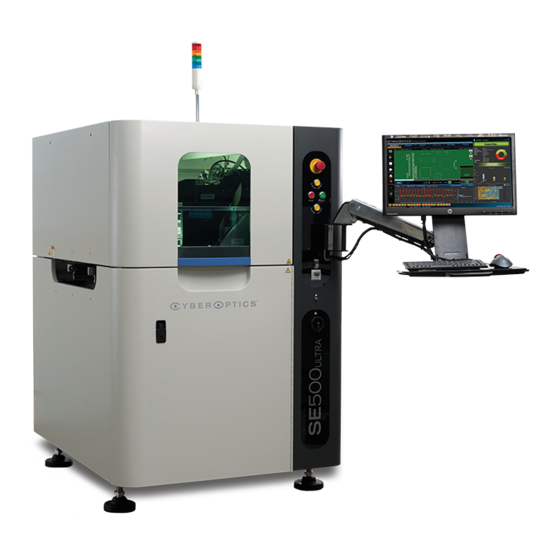
Chapter 1: System Overview SE500 ULTRA The SE500 is an inline Solder Paste Inspection system that inspects solder deposits. ULTRA The SE500 helps to prevent production problems by notifying operators when the print ULTRA process moves outside the control tolerances. The SE500 is intended to help Process ULTRA Engineers to establish process tolerances. - Page 13 SE500ULTRA Signal-light pole Safety enclosure hood Flat-panel display Control panel (see below) Keyboard and trackball tray Air pressure gauge ESD wrist strap connection Power Switch Leveling feet Control Panel E-Stop E-Stop Reset Start Alarm Stop Cancel Figure 1. Front View...
-
Page 14: Se500Ultra Rear View
Chapter 1: System Overview SE500 Rear View ULTRA System connections such as power, air, and I/O are accessed at the rear of the machine as shown in Figure 2 and shown below . Table 2. SE500 System Components ULTRA Component Description AC Circuit Breaker The main circuit breaker is located on the rear electrical panel;... - Page 15 SE500ULTRA Power access cover COM1 port Back access cover COM2 port Ethernet port SMEMA Upstream Cooling fans SMEMA Downstream Digital I/O Air regulator AC circuit breaker Power cord strain relief (Circuit Breaker 1) Figure 2. Rear View CyberOptics Corporation...
-
Page 16: Se500Ultra Internal Parts
Chapter 1: System Overview SE500 Internal Parts ULTRA Opening the hood, which stops all machine motion, gives you access to the sensor, gantry and conveyor. The lower panel can be removed (by service personnel only) to gain access to internal electrical components. - Page 17 SE500ULTRA Sensor Conveyor Gantry PLC Controller Processor Main Electrical panel Figure 3. Internal Components CyberOptics Corporation...
-
Page 18: Main Electrical Panel
Chapter 1: System Overview Main Electrical Panel The Main Electrical Panel in the SE500 contains the electronic components described in ULTRA the following table and shown in Figure 4. Table 4. Main Electrical Panel Components Component Description Middleman PCB Assembly Collects encoder and sensor information and transfers it to the processor for analysis. - Page 19 SE500ULTRA Fixed Rail Motor Belt Motor Controller Y-Stage Servo Amp X-Stage Servo Amp Z-Stage Servo Amp TOWER SYSTEM SMEMA Middleman Assembly PS1–3.5 A PS2–5 A CB2–CB8 Contactor, 18 A PS3–5 A 24 VDC, Coil Safety Relay 6 .0 A 6.0A 6 .0 A...
-
Page 20: Conveyor
Chapter 1: System Overview Conveyor The SE500 receives panels from the upstream conveyor using SMEMA signals to control ULTRA the timing, it clamps the panel into position and also supports the panels with the lift to hold it in place during inspection. When the inspection is complete, the machine releases the panel to the downstream conveyor utilising SMEMA signals for timing. - Page 21 SE500ULTRA Movable Conveyor Rail Top Clamp Rear Conveyor Belt Panel Detect Sensor (Entry/Exit) Panel Lifter Board Stop Sensor Panel Detect Sensor (Entry/Exit) Conveyor Motor Board Stop Slow Speed Fixed Conveyor Rail Autowidth Motor Conveyor Drive Belt (option kit) Sensor Conveyor Manual Adjustment Wheel Note: SE500 does not come with autowidth function as a basic configuration.
- Page 22 Chapter 1: System Overview ➢ To configure the conveyor for Board Flow 1. Connect the board stop at the fixed conveyor rail as shown in Figure 7 for Left to Right configuration which is the default configuration. 2. T o change to use the Right to Left configuration, unscrew the two nuts on the board stop. Note: Set the ConveyorRightToLeft value using the Configuration Editor.
- Page 23 SE500ULTRA ➢ To configure the conveyor software settings for Board Flow 1. Backup the Configuration folder located at C:\Program Files\CyberOptics\SE500 System Software in a safe place for future use. 2. Navigate to C:\Program Files\CyberOptics\SE500 System Software. 3. Double-click SystemSetup.exe. The System Setup dialog box automatically pops up.
- Page 24 Chapter 1: System Overview 13. Select the Set search area as (8.00x8.00 mm) check box. 14. Click START to align the fiducial to the center of the image. 15. Choose Camera Rotation to align the camera. Camera Rotation (degrees): indicates the number of degrees the camera angle needs to ●...
-
Page 25: System Specifications
SMEMA (Per IPC-SMEMA-9851), Ethernet, RS232, Digital I/O, air, power 24 GB recommended Available Disk Space 750 GB Video card Minimum 256 MB memory ● ● Recommended 512 MB memory, OpenGL acceleration Height equivalent of the least significant bit. CyberOptics Corporation... -
Page 26: System Requirements
Chapter 1: System Overview There is an option for upgrading the system processor. Contact CyberOptics for more information. System Requirements Table 7. System Requirements Humidity Operating 20–80% RH non-condensing ● Storage 10-90% RH non-condensing ● Temperature ● Operating (Ambient) 15°– 35° C (59°–95° F) ●... -
Page 27: Performance Specifications
Performance Specifications Performance Specifications The most current performance specifications are found on the product page of the CyberOptics Web site at http://www .cyberoptics.com. Computer Requirements Y ou can run the T each application on a desktop computer that meets the following minimum requirements: Table 8. -
Page 28: Dimensions
Chapter 1: System Overview Dimensions Figure 8. Front View SE500 Hardware Manual ULTRA... - Page 29 Dimensions *To achieve the lowest conveyor height configuration of 83 cm to 96 cm (33 inch to 38 inch), a customized conversion kit is needed. Contact CyberOptics for more information. Figure 9. Side View CyberOptics Corporation...
- Page 30 Chapter 1: System Overview SE500 Hardware Manual ULTRA...
-
Page 31: Installation
Installation Packing the SE500ULTRA Unpacking the SE500ULTRA Choosing a Location Installing the System Wiring SE500ULTRA for Power Connecting the Air Supply Connecting SMEMA Cables Connecting to a Network Connecting to an External Device Wago PLC Assembly Manually Adjusting the Conveyor Width... - Page 32 Chapter 2: Installation Warning: Only CyberOptics’ service personnels shall perform the installation procedures in this Chapter. Packing the SE500 ULTRA These instructions describe how to pack the SE500 in its original wooden shipping crate ULTRA for shipment. It is recommended to save the shipping crate and all of the packing materials in case you need to ship the SE500 back to CyberOptics.
- Page 33 Packing the SE500ULTRA ➢ Packing Accessories 1. Place foam padding between the keyboard, flat screen display and front cover of machine. 2. Place one moisture barrier and two desiccant clay packets at the rear and the stage of the machine and seal as shown.
- Page 34 Chapter 2: Installation 6. Using the drill, a 13 mm socket attachment and hex head bolts, secure the lockdown plate over each of the leveling foot. 7 . Shrink wrap the machine and the accessories. Ensure that necessary transit securing brackets are fixed to the X and Y axes Note: before closing the crate and shipping the system.
-
Page 35: Unpacking The Se500Ultra
Unpacking the SE500ULTRA Unpacking the SE500 ULTRA These instructions describe how to unpack the SE500 from its shipping crate. It is ULTRA recommended to save the crate and all of the packing materials. Performing this procedure requires a drill with a 13 mm socket attachment, a forklift, and a pallet jack. -
Page 36: Choosing A Location
Chapter 2: Installation 8. Lower the leveling feet sufficiently to allow the forks of a pallet jack or a forklift under the machine. 9. Using a pallet jack or forklift, move the machine to a desired location. 10. Remove all the transit securing brackets on X and Y axes before using the machine. Figure 10. -
Page 37: Installing The System
T o ensure optimum performance Caution: ULTRA of your SE500 , a trained CyberOptics service representative is required to install the ULTRA system. Installing the SE500 system consists of the general steps listed below . Each step is ULTRA described in more detail on the following pages. - Page 38 Chapter 2: Installation Positioning / Leveling the SE500 ULTRA Adjust the height of the system to align with incoming and outgoing conveyor sections. System height can be configured at a standard height or can be lowered 5 cm (2 inch.) by repositioning the leveling foot block.
- Page 39 (vertical) from the control panel area (see Figure 15 on page 30). Note: T o achieve the lowest conveyor height configuration of 83 cm to 96 cm (33 inch to 38 inch), a customized conversion kit is needed. Contact CyberOptics for more information. ➢...
- Page 40 Chapter 2: Installation ➢ To remove the front panels If the side panels cannot be removed, remove both the front panel and the right front (vertical) panel. 1. Lift the system hood. 2. Make sure all motion has stopped. 3. Lift up the swing door latch and turn in a clockwise direction to open the swing door. 4.
- Page 41 SE500 conveyor rail is properly aligned. The panel should pass from the ULTRA upstream conveyor through the SE500 and on to the downstream conveyor without any ULTRA resistance. 10. After adjusting the leveling feet, tighten the locking nuts. CyberOptics Corporation...
-
Page 42: Installing The Sensor
Chapter 2: Installation Installing the Sensor Make sure the SE500 system power is off before installing the sensor. The sensor Caution: ULTRA could be damaged if you connect it to the system when power is on. ➢ To install the sensor 1. - Page 43 Installing the System 5. Connect the flat white Camera Link cable to the connector on the back of the sensor and tighten the two small screws. Illumination Control cable connection Camera Link cable connection Figure 19. Sensor Cable Connections CyberOptics Corporation...
-
Page 44: Wiring Se500Ultra For Power
Chapter 2: Installation Wiring SE500 for Power ULTRA The SE500 must be hard-wired into your AC main power. Have a certified electrician to ULTRA wire the system. Before wiring the system, make sure that the AC main power supply is turned off and Caution: locked off. - Page 45 Wiring SE500ULTRA for Power 4. Feed the incoming power lines through the strain-relief connector. Power Cord (AWG 14–16) Screwdriver Stripped wire Voltage (VAC) 110 VAC 240 VAC Power Cord 14-16 Pry open the crimping (AWG) connector using a screwdriver and insert...
-
Page 46: Turning On System Power
Chapter 2: Installation Turning on System Power CyberOptics recommends a 30 minute warm up time to ensure the most accurate system measurements. ➢ To turn on the system 1. Check to make sure the conveyor is clear of panels and the E-Stop button is engaged. -
Page 47: Connecting The Air Supply
Figure 23. Connecting to the Air Regulator Note: The default setting for the air pressure gauge should display the air pressure in psi. If not, or to change other settings on the gauge, refer to “ Configuring the Pressure Gauge Display” on page 43. CyberOptics Corporation... -
Page 48: Connecting Smema Cables
Chapter 2: Installation Connecting SMEMA Cables Use the SMEMA connections to facilitate board handling between machines in the SMT line. ➢ To connect SMEMA cables 1. Shut down Windows and then push the E-Stop button on the front of the unit. 2. -
Page 49: Connecting To A Network
Use the Windows network tools to complete the Ethernet configuration. This is typically done by a network administrator and includes the following: Adding the protocol ● Assigning the IP address ● Configuring the Domain Name System (DNS) ● CyberOptics Corporation... -
Page 50: Connecting To An External Device
Chapter 2: Installation Connecting to an External Device This section describes how to connect a device such as a stacking or diverting conveyor to the SE500 . CyberOptics provides a 14-pin digital I/O connector to interface with the external ULTRA device. ➢... -
Page 51: Wago Plc Assembly
(6.3 A). After testing, 1.6 A fuse is the best option. Warning: The maximum current of the supply module is 6.3 A. When configuring the system, it is important not to exceed the maximum/sum current. T6.3A 250V Figure 27. WAGO PLC Assembly CyberOptics Corporation... -
Page 52: Manually Adjusting The Conveyor Width
Chapter 2: Installation Manually Adjusting the Conveyor Width The system conveyor is equipped with automatic width adjustment and adjusts to the width specified in the SRFF when the file is opened. Y ou can adjust the conveyor manually as described below . ●... -
Page 53: Configuring The Pressure Gauge Display
2. Set the low trigger set point by pressing to cycle through the values. 3. Stop on the value and wait 5 seconds to end programming mode. 4. Press . Set mode will appear for 1 second followed by b-1 (High set point) CyberOptics Corporation... - Page 54 Chapter 2: Installation 5. Set the high trigger set point by pressing to cycle through the values. 6. Stop on the value and wait 5 seconds to end programming mode. Note: if H-1or h-1 appears instead, change the operating output mode as described in “ To set the operating mode”...
-
Page 55: Setting Up System Security
Lead Operator ● Operator ● Anyone using the SE500 can use one of the default logons (password CyberOptics). The ULTRA default setup allows full access to all SE500 features for all users except for the Security ULTRA Setup feature. Only the Supervisor logon has rights to change the Security Setup by default. -
Page 56: Adding Users To The System
Chapter 2: Installation Adding Users to the System Use the Windows system User Accounts to add users to the system 1. On the Windows taskbar, click Start and then click Control Panel . 2. Double-click Administrative Tools . 3. Double-click Computer Management . 4. - Page 57 16. In the Select Groups dialog box, Enter object names to select box, type the name of the Group to which the new user belongs. 17 . Click Check Names . 18. Click OK in the Select Group and Properties dialog boxes. CyberOptics Corporation...
-
Page 58: Assigning Secure Areas
Chapter 2: Installation Assigning Secure Areas Each of the following Secure Areas must be assigned to one of the four SE500 groups ULTRA (Supervisor, Engineers, Lead Operators, Operators) from within the SE500 applications. ULTRA Each group inherits the rights assigned to the group or groups below it. For more information about how to assign Secure Areas, refer to “... - Page 59 5. Click on OK to save your changes or Cancel to close the window without making changes. When you click OK, your changes are saved to a file named SE500 .sec located in the ULTRA default security directory . The settings in the security file are loaded each time the application starts. CyberOptics Corporation...
-
Page 60: Verifying System Accuracy
CyberOptics Certificate of Traceability CyberOptics provides a certificate of traceability with each certification target. The certificate includes the serial number and the certified measurements for the certification target. SE500... - Page 61 Verifying System Accuracy CyberOptics can recertify the certification target and issue a new certificate of traceability as needed for your equipment requirements. T o re-certify your certification target, contact CyberOptics Service and Support (See “ T echnical Support” on page ix.).
-
Page 62: Shutting Down The System
Chapter 2: Installation Shutting Down the System ➢ To shut down the system 1. Stop the inspection process. 2. Press the E-Stop button. 3. Close the inspection application. 4. On the taskbar, click Start and then click Shut Down to shut down the system processor. T urning off power at the power switch does not remove power from the processor. -
Page 63: Moving The Se500Ultra System
Moving the SE500ULTRA System Moving the SE500 System ULTRA The SE500 unit weighs approximately 854.5 kg (1883.8 lbs.). T o avoid injury , Caution: ULTRA always use a forklift or a pallet jack to move the unit. The forklift’s forks need to securely hold both cross beams under the unit. - Page 64 Chapter 2: Installation 5. On the left side of the digital I/O controller, turn the bypass switch from NORMAL to BYP ASS. Bypass switch Figure 30. Bypassing the System 6. Replace the lower font panel and close the hood. 7 . Restore system power. Note: The conveyor width must be manually adjusted and the E-Stop must be released for the system to work.
-
Page 65: Replacing Components And Preventive Maintenance
Replacing Components and Preventive Maintenance Maintenance Schedule Main Electrical Panel Processor Components Conveyor Components Gantry Components Other Components CyberOptics Corporation... -
Page 66: Maintenance Schedule
Chapter 3: Replacing Components and Preventive Maintenance Maintenance Schedule Perform the maintenance procedures in this section as specified in the maintenance schedule below . Perform maintenance more frequently as required, based on machine usage. Warning: T o prevent the risk of injury , turn the AC main circuit breaker to OFF to shut down all electrical power to the SE500 before starting any replacement operations. -
Page 67: Main Electrical Panel
Warning: T o prevent the risk of injury , turn the AC main circuit breaker to OFF to shut down all electrical power to the SE500 before starting any replacement operations. For more ULTRA information, refer to the section “ Shutting Down the System” on page 52. CyberOptics Corporation... - Page 68 Chapter 3: Replacing Components and Preventive Maintenance ➢ To replace DIN rail-mounted components 1. T urn off all electrical power to the system. For more information, refer to the section “ Shutting Down the System” on page 52. 2. Open the hood on the SE500 ULTRA 3.
- Page 69 Z-Stage Servo Amp TOWER SYSTEM SMEMA Middleman Assembly PS1–3.5 A PS2–5 A Contactor, 18 A PS3–5 A Safety Relay 24 VDC, Coil N–PE CB2–CB8 6.0A 6.0A 6.0A 6.0A 10.0A 10 .0A 10 .0A Figure 32. Main Electrical Panel CyberOptics Corporation...
-
Page 70: Replacing Electrical Cables
COM1 Fix Belt 8012970 (8014683) Fix Belt Y Encoder 8013776 Move Belt 8012800 Move Belt (0 in SE350, SE500cp, SE500ultra) 8013720 Width 2 (only in SE500-D) RS232 8013777 Z Encoder 8014489 Width 2 (only in SE500-D) Conveyor 2 (only in SE500-D) -
Page 71: Replacing The Ac Main Circuit Breaker
Replacing the AC Main Circuit Breaker Parts AC Main Circuit Breaker Note: For Parts Replacement, contact CyberOptics for part numbers. Warning: Hazardous voltages may be present. Make sure that power is disconnected from the mains before replacing the AC Main circuit breaker. - Page 72 Chapter 3: Replacing Components and Preventive Maintenance (Loosen) screws (x 4) Back Electrical Panel Power access cover Strain relief nut AC main circuit breaker (CB1) Power Cord Pry open the crimping (AWG 14–16) connector using a screwdriver and insert the conductor.
-
Page 73: Replacing The Fuses
Replacing the Fuses Parts Fuse 10 A Fuse 6 A Note: For Parts Replacement, contact CyberOptics for part numbers. Warning: Hazardous voltages may be present. Make sure that power is disconnected from the mains before replacing the fuse. ➢ To replace the fuse 1. - Page 74 Chapter 3: Replacing Components and Preventive Maintenance Y-Stage Servo Amp Fixed Rail Motor Belt Motor Controller X-Stage Servo Amp Z-Stage Servo Amp TOWER SYSTEM SMEMA Middleman Assembly PS1–3.5 A PS2–5 A Contactor, 18 A PS3–5 A Safety Relay 24 VDC, Coil N–PE CB2–CB8 6.0 A...
-
Page 75: Replacing The Air Regulator
13. Attach the safety cover to the air regulator with the screw . 14. Reconnect and turn on the air supply . 15. T urn the knob at the top of the air regulator to set the air pressure to 90 psi ± 10 psi. CyberOptics Corporation... -
Page 76: Replacing Fans
Chapter 3: Replacing Components and Preventive Maintenance Replacing Fans Parts 8009605 Fan ➢ To replace a fan 1. T urn off all electrical power to the system. For more information, refer to the section “ Shutting Down the System” on page 52. Cooling Fan M4 screws x 4 Back Electrical Panel... -
Page 77: Preventive Maintenance
4. On the inside check the fans for dust buildup. Remove dust buildup using a dry cloth. Keep away from the system so the dust will not get into the electronics panel. 5. Set the AC main circuit breaker to ON. CyberOptics Corporation... - Page 78 Chapter 3: Replacing Components and Preventive Maintenance Cleaning Inside the Enclosure ➢ To clean inside the enclosure Warning: Make sure the AC main circuit breaker is turned OFF and power is disconnected from the mains before starting on any procedure. 1.
- Page 79 6. Rinse the filter in warm water and let it air dry . 7 . Replace the filter and bowl at the bottom of the regulator. Air supply fitting Air shut-off valve Bowl with filter Figure 39. Air Regulator CyberOptics Corporation...
- Page 80 Chapter 3: Replacing Components and Preventive Maintenance Checking the Emergency Stop Functionality Perform this procedure monthly or more frequently if required. Stop all movement on the SE500 system by using the Emergency Stop (E-Stop) button. ULTRA Motion will also stop when a safety interlock is disengaged. : Always press the Emergency Stop button before clearing a conveyor malfunction, Caution before performing machine maintenance, or before reaching inside the machine for any reason.
-
Page 81: Processor Components
15. Place the processor cover back. 16. Tighten the two thumb screws on the rear of the processor. 17 . Slide the processor back into the machine frame. 18. T urn the AC power switch at the rear of the processor to ON. CyberOptics Corporation... -
Page 82: Software Upgrades
Chapter 3: Replacing Components and Preventive Maintenance AC Power Switch Serial Port RS-232 Video Port (COM1) (on board) USB Ports Ethernet Ports Serial Port RS-232 (COM2) Graphic card Framegrabber card USB Ports CANOpen Interface card Figure 41. Card Locations in Processor Software Upgrades The SE500 software can be upgraded or re-installed from the DVD-R/W drive. -
Page 83: Restoring System Disk Using Acronis
If the computer will not start, boot from the Acronis Boot CD. T o do this: 1. Insert the Acronis Boot CD in the computer. 2. Start the computer. 3. At the Acronis Rescue Media Screen, select Acronis True Image (Full Version). CyberOptics Corporation... - Page 84 Chapter 3: Replacing Components and Preventive Maintenance Backing Up the Computer into DVD Using Acronis 1. Open the Acronis True Image Personal software and click the Backup icon as shown. 2. The Create Backup Wizard screen appears as shown. Click Next to continue. SE500 Hardware Manual ULTRA...
- Page 85 3. Select ONLY the NTFS (C:) drive to create the backup copy as shown. Click Next to continue. 4. Insert a blank DVD into the computer DVD-RW drive and select that drive letter and give the filename for the backup image. For example: E:/CYBERXXXX where XXXX is the serial number of the machine shown. CyberOptics Corporation...
- Page 86 Chapter 3: Replacing Components and Preventive Maintenance 5. Select Set the options manually option. Click Next to continue. 6. Click Media Components on the left side of the screen and select Place Acronis True under the General tab. This step will ensure that the Acronis Image (full version) on media software will also be backed up inside the DVD.
- Page 87 Processor Components 7 . Click Next to continue. 8. Make sure all checkboxes are not selected. Click Next to continue. CyberOptics Corporation...
- Page 88 Chapter 3: Replacing Components and Preventive Maintenance 9. Click Proceed to continue. 10. The Backup operation is now in progress. Do not close the window . Recovering the Computer Using Acronis 1. Load the Recovery Image that comes with the SPI machine in to the DVD drive and boot the computer.
- Page 89 Processor Components 2. Click Acronis True Image (Full Version) . 3. Click Recovery under Pick a Task options and the click Next to continue. CyberOptics Corporation...
- Page 90 Chapter 3: Replacing Components and Preventive Maintenance 4. The Restore Data Wizard welcome screen appears. Click Next to continue. 5. Navigate to the CD drive and select the .TIB file — that is the factory default recovery image for the machine. SE500 Hardware Manual ULTRA...
- Page 91 6. The Acronis software will prompt you to select a partition or disk to restore. Y ou must select ONL Y NTSC (C:) and click Next to continue. 7 . The Acronis software will prompt you to resize the recovered partition. Select No, I do not and click Next to continue. want to resize partitions CyberOptics Corporation...
- Page 92 Chapter 3: Replacing Components and Preventive Maintenance 8. Select NTFS(C:) ONLY when the Acronis software prompts you to select a target partition for the restore. 9. In the Restored Partition T ype screen, select Active and click Next to continue. SE500 Hardware Manual ULTRA...
- Page 93 Processor Components 10. The Acronis software will prompt you to if you intend to restore another partition. Select No. and click Next to continue. I do not 11. In the Restore Operation Options screen, click Next . CyberOptics Corporation...
- Page 94 Chapter 3: Replacing Components and Preventive Maintenance 12. The Acronis software will prompt you that it is ready to recover the image to the target partition. Click Proceed . 13. The Recovery process has now begun. Do not cancel or close the window . SE500 Hardware Manual ULTRA...
- Page 95 Processor Components Backing Up the Disk Image to Acronis Secure Zone 1. Open the Acronis True Image Personal software and click the Backup icon as shown. 2. The Create Backup Wizard screen appears as shown. Click Next to continue. CyberOptics Corporation...
- Page 96 Chapter 3: Replacing Components and Preventive Maintenance 3. Select ONLY the NTFS (C:) drive to create the backup copy . Click Next to continue. 4. Select Acronis Secure Zone and click Next to continue. SE500 Hardware Manual ULTRA...
- Page 97 Processor Components 5. Select Use default options option. Click Next to continue. 6. Click Media components on the left side of the screen and select Place Acronis True on media under the General tab. Image (full version) CyberOptics Corporation...
- Page 98 Chapter 3: Replacing Components and Preventive Maintenance 7 . Click Additional Settings on the left side of the screen and select Place Acronis True on media under the General tab. Make sure the check boxes are not Image (full version) selected and click OK to continue.
- Page 99 Processor Components 9. Click Proceed to continue. 10. The Backup operation is in progress. Do not close the window . CyberOptics Corporation...
-
Page 100: Preventive Maintenance
Chapter 3: Replacing Components and Preventive Maintenance Preventive Maintenance Backing Up Data After the SE500 is installed and running, and you have a database of stored assemblies ULTRA and models, copy the following files to a disk and store the disk in a safe place. SRFF files: ●... - Page 101 12. Reconnect the cables. See Figure 41 on page 72 for cable connections. 13. Slide the processor back into the machine and secure in place with two screws. 14. Replace the lower font panel. 15. Close the SE500 hood. ULTRA CyberOptics Corporation...
- Page 102 Chapter 3: Replacing Components and Preventive Maintenance ➢ To clean the processor’s air filter Warning: Make sure the AC main circuit breaker is turned OFF and power is disconnected from the mains before starting on any procedure. 1. T urn off all electrical power to the system. For more information, refer to the section “...
-
Page 103: Conveyor Components
Gantry motion can pinch or sever objects in its path. Parts T op Cap Extrusion Note: For Parts Replacement, contact CyberOptics for part numbers. Required Tools – No. 3 Allen Key – Mallet –... - Page 104 Chapter 3: Replacing Components and Preventive Maintenance 3. Make sure all motion has stopped. 4. Release the right-hand lock plate at the front clamp assembly in a clockwise direction. Release the left-hand lock plate in a counter clockwise direction. Left-hand lock plate Right-hand lock plate...
- Page 105 “ Replacing the Conveyor Belts” on page 104. ➢ To replace the edge guide at rear clamp assembly 1. Remove the five screws on the edge guide. 2. Replace with a new edge guide. 3. Use steps 9–13 to reassemble the top clamp. CyberOptics Corporation...
-
Page 106: Replacing The Conveyor Clamp Blade
Parts Conveyor Blade Note: For Parts Replacement, contact CyberOptics for part numbers. Required Tools – No. 4 Allen Key – Ball Pein Hammer –... - Page 107 2. Lower down the blade holder into the clamping position. Slide the clamp blade until the gap between the top guide and clamp blade is approximately 2.5–3 mm. 3. Tighten all the five blade mounting screws. 4. T est the clamper movement for up/down binding and interference. CyberOptics Corporation...
-
Page 108: Replacing The Conveyor Clamp Air Fittings
Exhaust Reducer 8000517 T eflon Thread Tape (½ inch) Note: For Parts Replacement, contact CyberOptics for part numbers. ➢ To replace an air fitting assembly 1. T urn off all electrical power to the system. For more information, refer to the section “... -
Page 109: Replacing The Conveyor Clamp Hall Effect Switch
Parts Hall Effect Switch Note: For Parts Replacement, contact CyberOptics for part numbers. ➢ To replace the hall effect switch 1. T urn off all electrical power to the system. For more information, refer to the section “... -
Page 110: Replacing The Conveyor Clamp Cylinder
Parts Conveyor Clamp Cylinder 8000517 T eflon Tape Note: For Parts Replacement, contact CyberOptics for part numbers. ➢ To replace the conveyor clamp cylinder 1. T urn off the air supply by turning the air shut-off valve to the horizontal position. - Page 111 13. Reattach the screw on the top of the cylinder, using a ½ inch wrench to support the clamp. 14. T urn on the air supply by turning the air shut-off valve to the vertical position. CyberOptics Corporation...
-
Page 112: Replacing The Conveyor Motors
This section shows the procedure performed when the machine is not in production line. Parts DC Brushless Motor Note: For Parts Replacement, contact CyberOptics for part numbers. Tools – Allen Key No. 2.5 ➢... - Page 113 9. Transfer the drive pulley to a new motor and tighten it, then replace it at the bracket and tighten back with screws. 10. Repeat step 10–11 for replacing the conveyor belt. Refer to the section “ Replacing the Conveyor Belts” on page 104. 11. Reverse the process to reassemble. CyberOptics Corporation...
-
Page 114: Replacing The Conveyor Belts
This section shows the procedure performed when the machine is not in production line. Note: For Parts Replacement, contact CyberOptics for part numbers. Parts Edge Belt Required Tools –... -
Page 115: Replacing The Drive Belts
This section shows the procedure performed when the machine is not in production line. Note: For Parts Replacement, contact CyberOptics for part numbers. Parts Autowidth Timing belt... - Page 116 Chapter 3: Replacing Components and Preventive Maintenance 4. Unscrew the shaft guide by using Allen key No. 3 and remove the drive pulley from the leadscrew . Figure 60. Shaft Guide and Drive Pulleys 5. Remove the timing belt from the motor drive pulley . Figure 61.
-
Page 117: Replacing The Idler Pulleys
This section shows the procedure performed when the machine is not in production line. Parts Idler Pulley Note: For Parts Replacement, contact CyberOptics for part numbers. Required Tool – No. 2.5 Allen Key ➢... - Page 118 Chapter 3: Replacing Components and Preventive Maintenance ➢ To set the belt tension 1. T o get the initial belt tension for setting 22 mm on the belt, push the Idler with minimum force slowly in the direction of the arrow shown in Figure 63. Stop pushing the idler when the belt is starting to strengthen.
-
Page 119: Replacing The Pulley Drive
This section shows the procedure performed when the machine is not in production line. Parts Pulley drive Note: For Parts Replacement, contact CyberOptics for part numbers. Required Tools – No. 2.5 Allen Key – No. 3 Allen Key ➢... -
Page 120: Replacing The Board Sensors
This section shows the procedure performed when the machine is not in production line. Parts Board Sensor Note: For Parts Replacement, contact CyberOptics for part numbers. ➢ To replace the board sensors 1. T urn off all electrical power to the system. For more information, refer to the section “... - Page 121 Conveyor Components Board sensor Mounting Sensor screws bracket Handwheel Board sensor Figure 67. Board Sensors on Conveyor CyberOptics Corporation...
-
Page 122: Replacing The Panel Lifter Cylinder And Inductive Sensor
This section shows the procedures performed when the machine is not in production line. Note: For Parts Replacement, contact CyberOptics for part numbers. Parts Panel Lifter Cylinder Required Tools –... - Page 123 10. Reverse the process to reassemble. Note: For more information on system alignment, refer to “ Aligning the System” section of the “ SE Series Solder Paste Inspection Software User Guide, Part Number: 8020277. CyberOptics Corporation...
-
Page 124: Preventive Maintenance
Chapter 3: Replacing Components and Preventive Maintenance Preventive Maintenance Cleaning the Panel Sensors The conveyor contains four sensors as shown in Figure 68. Warning: Make sure the system power is turned off before working inside the hood. Gantry motion can pinch or sever objects in its path. ➢... - Page 125 Figure 69. Stopper Sensor Bracket Thumb screws 4. Remove the stopper sensor bracket from the conveyor. Re-tightened the thumb screws back. 5. Unlock the two wing nuts and keep the wing nuts in a safe place. Wing Nuts Figure 70. Stopper Bracket Wing nuts CyberOptics Corporation...
- Page 126 Chapter 3: Replacing Components and Preventive Maintenance 6. Use a cutter to cut the cable tie. Cutter Figure 71. Stopper Cable tie Figure 72. Stopper Sensor Bracket dismantled from the conveyor 7 . Take out the stop spacer from the cylinder by using the Allen key No. 2.5. Allen Key No.
- Page 127 9. Re-assemble the cylinder on the bracket using Allen key No. 2.5. Apply adequate amount of Loctite before tightening. Figure 76. Stopper bracket assembly in the opposite side Note: Ensure the stopper bracket is turned to the opposite side and apply Loctite before tightening. CyberOptics Corporation...
- Page 128 Chapter 3: Replacing Components and Preventive Maintenance 10. Re-assemble the stop spacer and align the flange with the top edge properly with Allen key No. 2.5. Ensure that the flange is close to the cylinder top edge. Apply loctite to the bolts. Figure 77.
- Page 129 14. Tidy the cable routing with cable tie onto the cable mount. Figure 82. Cable Routings 15. Reset the conveyor offset after the relocation of the mechanical board stop is completed. For more information, refer to the section “ To reset the conveyor offset settings” on page 123. CyberOptics Corporation...
- Page 130 Chapter 3: Replacing Components and Preventive Maintenance ➢ To relocate the Slow Down Sensor 1. Loosen the slot nut as shown in Figure 83 to adjust the slow down sensor position. Slot Nut Figure 83. Slow Down Sensor Location 2. Use a cutter to cut the cable tie. Figure 84.
- Page 131 4. Re-route the existing wiring route. Figure 86. Re-routing the wiring 5. Move the slow down sensor from left hand side to right hand side. Figure 87. Moving slow down sensor 6. Re-connect the connector. Figure 88. Re-connect Connector CyberOptics Corporation...
- Page 132 Chapter 3: Replacing Components and Preventive Maintenance 7 . Set the distance of 52 mm by using a steel ruler or a 52 mm plate between the slow down sensor and the stopper spacer. Once the distance is set, secure the position with Allen key No.
- Page 133 1. Run SystemSetup.exe . In the System Setup dialog, choose the appropriate system type, conveyor orientation, lane configuration and rail configuration. 2. Select the desired fudicial. 3. Run the Inspection. 4. Conveyor offsets are automatically saved, no manual adjustments are needed. CyberOptics Corporation...
-
Page 134: Gantry Components
This section shows the procedure performed when the machine is not in production line. Parts Forcer Note: For Parts Replacement, contact CyberOptics for part numbers. Required Tools – 1.4 mm spacer – Threadlock Sealant Remove the stator first before replacing the forcer. - Page 135 2. Remove the forcer and hall sensor connectors. 3. Remove all the cable ties. 4. Remove all the screws. Cable ties Forcer and hall sensor connectors cables screws 5. Remove the forcer and the hall sensor. Forcer and hall sensor CyberOptics Corporation...
- Page 136 8. Replace back the forcer, hall sensors connectors and cables. 9. Check the air gap between the hall sensor and the stator with a 1.4 mm spacer. The air gap must be maintained at a 1.4 mm gap width. Contact CyberOptics for the part number of the spacer.
-
Page 137: Replacing The Gantry Stator
Use this procedure to replace the stator on the left or right side of the gantry . This section shows the procedures performed when the machine is not in the production line. Parts Stator Note: For Parts Replacement, contact CyberOptics for part numbers. Required Tools – Threadlock Sealant – Ironless container (For easy handling and housekeeping of the stators) Since the stator has a very strong magnetic attractive force. - Page 138 Chapter 3: Replacing Components and Preventive Maintenance 5. Slide out the middle stator and place it in another ironless container. Middle stator 6. Slide out the last stator and keep it away from the other two stators. Last stator All stators removed 7 .
- Page 139 Gantry Components 11. Be sure to keep the stator’s S-mark connecting to the N-mark of the neighboring stator. Stator N-mark S-mark CyberOptics Corporation...
-
Page 140: Replacing The X-Axis
Parts X-Axis Note: For Parts Replacement, contact CyberOptics for part numbers. ➢ To replace the X-Axis of the gantry 1. T urn off all electrical power to the system. For more information, refer to the section “... - Page 141 5. Remove all the screws attached to the right endplate. screws screws screws 6. Remove the encoder grounding cable and D-sub connector. Grounding Cable D-sub connector 7 . Remove all the screws attached to the left endplate. screws screws screws screw CyberOptics Corporation...
- Page 142 Chapter 3: Replacing Components and Preventive Maintenance 8. Remove Y-axis stator. 9. Remove the two screws attached to the base of the two endplates. Left Side endplate screw Right Side endplate screw 10. Remove the X-axis. X-axis 11. Replace with a new X-axis. Reattach the two screws to the base of the two endplates. 12.
-
Page 143: Replacing The Encoder
Parts Encoder Note: For Parts Replacement, contact CyberOptics for part numbers. ➢ To replace the encoder 1. T urn off all electrical power to the system. For more information, refer to the section “... -
Page 144: Preventive Maintenance
Chapter 3: Replacing Components and Preventive Maintenance Preventive Maintenance Cleaning the Encoder Strips Encoder strips are located on the gantry along the X and Y axes. There are two encoder strips for the X axis. (Left to right) Warning: Make sure the system power is turned off and locked off before working inside the hood. - Page 145 “ Shutting Down the System” on page 52. 2. Remove all screws on both sides of the stage. Side plate 3. Remove the side plate. 4. Loosen the screw on the encoder bracket and remove the encoder. Encoder bracket 5. Remove the encoder strip. CyberOptics Corporation...
- Page 146 Chapter 3: Replacing Components and Preventive Maintenance 6. Replace the new encoder strip with the standard tool by pasting the strip onto the gantry . Contact CyberOptics for the part number of the standard tooling kit. Standard Tooling kit Encoder Strip 7 .
- Page 147 Screw Screw Figure 91. Encoder carrier screws 6. Insert a RENISHAW 0.8mm spacer between the read head and the scale. Contact CyberOptics for the part number of the REINSHAW spacer. REINSHAW 0.8 mm Spacer Do not scratch the scale. Caution: 7 .
- Page 148 Chapter 3: Replacing Components and Preventive Maintenance 9. If this is done properly , the required air gap can be achieved and the green LED light should be ON. Carrier 10. Slightly move the carrier and make sure that the green light is ON during the whole travel. 11.
- Page 149 Figure 92. Grease Fittings 4. Using a grease gun with a tapered nozzle fitting, pump grease into each fitting until grease is visible around the fittings. 5. Slide the stage back and forth manually . 6. Wipe off grease overflow . CyberOptics Corporation...
- Page 150 Chapter 3: Replacing Components and Preventive Maintenance ➢ To lubricate the Z-Stage leadscrew 1. T urn off all electrical power to the system. For more information, refer to the section “ Shutting Down the System” on page 52. Warning: Make sure the system power is turned off before working inside the hood. Gantry motion can pinch or sever objects in its path.
-
Page 151: Adjusting X-Axis Parallelism
“ Shutting Down the System” on page 52. 2. Set a target within 5 μm for the reference guideway . Target set within 5 µm 3. Set a target within 5 μm for the following guideway . Tightening torque Target within 5 µm at 90kgf.cm CyberOptics Corporation... -
Page 152: Adjusting Y-Axis Parallelism
Chapter 3: Replacing Components and Preventive Maintenance Adjusting Y-Axis Parallelism This procedure is to adjust the Y-axis parallelism of the gantry stage. This procedure can be performed with access to the left/right of the machine in production line. This section shows the procedure performed when the machine is not in production line. -
Page 153: Adjusting X-Axis And Y-Axis Orthogonality
1. T urn off all electrical power to the system. For more information, refer to the section “ Shutting Down the System” on page 52. 2. Place the square granite ruler and indicators. Contact CyberOptics for the part number of the granite ruler and indicator. - Page 154 Chapter 3: Replacing Components and Preventive Maintenance 3. Make Y-axis as the reference. Y Indicators 4. Set a target within 5μm and adjust the X-Axis. screw adjustment Target set within 5µm SE500 Hardware Manual ULTRA...
-
Page 155: Sensor
CyberOptics warranty . If you have problems with the sensor or you suspect that the sensor needs to be replaced, call your CyberOptics Service and Support representative. (See “ Technical Support” on page ix) ➢ To replace the sensor 1. - Page 156 Chapter 3: Replacing Components and Preventive Maintenance Captive screw Top mounting pin Z Stage Captive screw Captive screw Bottom mounting pin Figure 94. Mounting Plate on the Z-Stage Illumination Control cable connection Camera Link cable connection Figure 95. Sensor Cable Connections SE500 Hardware Manual ULTRA...
- Page 157 Loading T olerance value back to its default value. 6. Repeat step 5 until the camera rotation values are within the specified limits. 7 . Once the rotational alignment is complete, close the Recipe and reopen it for the changes to take effect. CyberOptics Corporation...
-
Page 158: Other Components
Parts Safety Interlock Switch Safety Interlock Key Note: For Parts Replacement, contact CyberOptics for part numbers. ➢ To replace the safety interlock switch 1. T urn off all electrical power to the system. For more information, refer to the section “... - Page 159 2. Close the hood to make sure the pin is lined up with the safety interlock switch socket. T o check the alignment: Re-engage the E-Stop. ● Observe the safety circuit relays inside the electronics panel. The LEDs should be turned ● 3. Adjust the switch for correct alignment and tighten the mounting screws. CyberOptics Corporation...
-
Page 160: Replacing Leveling Feet
5. Repeat steps 1– 4 as required to replace the other leveling feet. 6. Adjust the leveling feet as needed to align the SE500 with the conveyors. For more ULTRA information, refer to the section “ Positioning / Leveling the SE500ULTRA” on page 28 for details. Locking nut Adjustment nut Figure 98. -
Page 161: Troubleshooting
Troubleshooting Safety Circuit Block Diagram AC and DC Distribution Block Diagram SMEMA Connector Pinout System Error Messages Solder Paste Failure Causes CyberOptics Corporation... -
Page 162: Safety Circuit Block Diagram
Chapter 4: Troubleshooting Safety Circuit Block Diagram CyberOptics Corp. Dwg. No. 8020054 Date: Sept. 06, 12 Schematic, System, Elec. SE500ultra SE500ultra DC Distribution Rev C Components connected with dot PS2 DC 8012956 line is optional for auto-Width. Y Servo Drive... -
Page 163: Ac And Dc Distribution Block Diagram
AC and DC Distribution Block Diagram AC and DC Distribution Block Diagram CyberOptics Corporation... -
Page 164: Smema Connector Pinout
Chapter 4: Troubleshooting SMEMA Connector Pinout The SMEMA cables allow the SE500 to communicate with the upstream and downstream ULTRA conveyors. For more information about SMEMA cables, refer to “ Connecting SMEMA Cables” on page 38. SMEMA Connector Upstream Cable Downstream Cable 1 - 2 Machine Ready... -
Page 165: System Error Messages
. This log file provides sufficient information to diagnose the problem or report the problem to CyberOptics Service and Support for further analysis. Y ou can configure the logging options under T ools>Options>Advanced tab to record additional information in the MachineControl.log file. -
Page 166: Solder Paste Failure Causes
Chapter 4: Troubleshooting Solder Paste Failure Causes Failure Possible Cause Evidence Mode Lack of Support Board flexes while pressed on when locked in print position Print speed too fast Paste left on stencil behind squeegee Print pressure too low Paste left on stencil behind squeegee High Height Contamination on board Localized issue, usually on one board. - Page 167 High Volume while printing should be very close. Board support while printing Board flexes while pressed on when locked in print position Damaged Squeegees Check blades for damage - usually results in line of defects, front to back. CyberOptics Corporation...
-
Page 168: Sos
4. Right-click the value and click Properties . 5. Edit the value from 0 to 1. 6. Click OK . This configuration setting must only be changed under the supervision of Caution: CyberOptics Service and Support personnel. SE500 Hardware Manual ULTRA... -
Page 169: System Drawings
System Drawings 8015066 ASSY, MAIN ELECTRICAL PANEL, SE500ULTRA 8016704 Conveyor SE500ULTRA... -
Page 170: 8015066 Assy, Main Electrical Panel, Se500Ultra
8015066 ASSY, MAIN ELECTRICAL PANEL, SE500 ULTRA Drawing Figure 99. 8015066 ASSY, MAIN ELECTRICAL PANEL, SE500 (Sheet 1 of 6) ULTRA... - Page 171 Figure 100. 8015066 ASSY, MAIN ELECTRICAL PANEL, SE500 (Sheet 2 of 6) ULTRA...
- Page 172 Figure 101. 8015066 ASSY, MAIN ELECTRICAL PANEL, SE500 (Sheet 3 of 6) ULTRA...
- Page 173 Figure 102. 8015066 ASSY, MAIN ELECTRICAL PANEL, SE500 (Sheet 4 of 6) ULTRA...
- Page 174 Figure 103. 8015066 ASSY, MAIN ELECTRICAL PANEL, SE500 (Sheet 5 of 6) ULTRA...
- Page 175 Figure 104. 8015066 ASSY, MAIN ELECTRICAL PANEL, SE500 (Sheet 6 of 6) ULTRA Note: The part numbers that are appended with ITEM, for example, 2X 8019437_ITEM10 are not FRU parts and are not sold by CyberOptics.
-
Page 176: 8016704 Conveyor Se500Ultra
8016704 Conveyor SE500 ULTRA Drawing 8016704 Conveyor for SE500CP and SE500 18 Sep 2013 ULTRA Spare Part Location Map Figure 105. 8016704 Conveyor SE500 (Sheet 1 of 8) ULTRA... - Page 177 Spare parts list for SE-350-L (New Clamp)-8016818 Description Use Quantity CyberOptics Part Number Motor Wire Harness FIXED RAIL (M1) 1 pc / unit 8014333 Motor Wire Harness WIDTH MOTOR (WM) 1 pc / unit 8014337 Proximity sensor with wire Assy...
- Page 178 Description Use Quantity CyberOptics Part Number Solenoid Valve, SY3103120-5LZD-C4-Q 3 pcs / unit 8014349 Timing belt 1 pc / unit (Width Adjust) 8014350 10W T5 900L Timing belt 1 pc /unit 8014352 (Auto Width Adjust Motor) 10W T5 275L Timing belt...
- Page 179 Description Use Quantity CyberOptics Part Number Clamp Blade 2 pcs / unit 8015956 Cylinder, Clamp Blade 2 pcs / unit 8014957 CDQSD16-10D-A93LS Cylinder, Lifter 1 pc / unit 8014579 CDQ2A20-30D-A73 Cylinder, Board Stop 1 pc /unit 8014580 CDQMB12-30-A93LS Stop Spacer / Block...
- Page 180 Description Use Quantity CyberOptics Part Number Flow Control 2 pcs / unit 8014593 AS1001F-04 Clamps Y Joint Fitting Kit 1 set /unit 8014602 KQ2U04-00 AS1001F-04 Note : W/O tubing Handwheel 1 pc / unit 8015958 (Include Handwheel-5202507, Spacer-5202508, Timing Pulley-5202856 &...
- Page 181 Description Use Quantity CyberOptics Part Number Clamp Rear Up & Down Proximity Sensor Wire Harness 1 pc / unit 8014610 Clamp Front Up & Down Proximity Sensor Wire Harness 1 pc / unit 8014612 Auto Width Home Sensor Wire Harness...
- Page 182 Description Use Quantity CyberOptics Part Number Cableveyor 1 pc / unit 8016819 CPS015-20-R28-B2-600L Linear Bushing 4 pc / unit 8016299 LMH 12 UUN Support Plate 1 pc / unit 8019008 Yoke Plate 2 pcs / unit 8016824 Supernut 2 pcs / unit...
- Page 183 Note : The lead time of delivery depending on stock level CyberOpticsSP_V2_20101228 Figure 112. 8016704 Conveyor SE500 (Sheet 8 of 8) ULTRA Note: The part numbers that are appended with ITEM, for example, 2X 8019437_ITEM10 are not FRU parts and are not sold by CyberOptics.
-
Page 185: Index
Numerics motor controller description 8 Board clamp 8015066 ASSY, MAIN ELECTRICAL PANEL, description 10 SE500ULTRA 160 Board stop, mechanical 8016704 Conveyor SE500ULTRA 166 description 10 Bypassing system 53 AC circuit breaker location 4 Cables AC main circuit breaker Replacing 60... - Page 186 Index replacing cylinder 100 encoder, adjusting 137 replacing Hall effect switch 99 encoder, replacing 133 Conveyor Components 93 forcer, replacing 124 location 7 Conveyor offset reset settings 123 lubricating 139 Conveyor width motor controller stator, replacing 127 description 8 x-axis, replacing 130 Cooling fans description 4 Cylinder (conveyor clamp), replacing 100...
- Page 187 System computer processor components 71 description 6 pulleys 107 location 7 safety interlock switch 148 replacing components 71 sensor 145 x-axis 130 replacing X-Axis 130 Trackball Replacing Cards 71 description 2 Replacing the Conveyor Belts 104 location 3 Requirements CyberOptics Corporation...
- Page 188 Index Unpacking system 25 USB port description 4 Verifying system accuracy 50 WAGO PLC assembly 41 Website ix Wiring the system 34 X-Axis parallelism, adjusting 141 X-Stage servo amp description 8 Y-Axis parallelism, adjusting 142 Y-Stage servo amp description 8 Z-Stage lubricating lead screw 140 Z-Stage servo amp...
Need help?
Do you have a question about the SE500ULTRA and is the answer not in the manual?
Questions and answers