Table of Contents
Advertisement
Quick Links
Advertisement
Table of Contents

Related Manuals for Allot NetEnforcer AC-2500 Series

Summary of Contents for Allot NetEnforcer AC-2500 Series
- Page 3 NetEnforcer AC-2500 Series Policy Based Bandwidth Management Hardware Guide P/N D360002 R2...
- Page 5 Important Notice Allot Communications Ltd. ("Allot") is not a party to the purchase agreement under which NetEnforcer was purchased, and will not be liable for any damages of any kind whatsoever caused to the end users using this manual, regardless of the form of action, whether in contract, tort (including negligence), strict liability or otherwise.
-
Page 6: Printing History
Important Notice Printing History First Edition: October, 2006 Second Edition: September, 2007 AC-2500 Series Hardware Guide... -
Page 9: Table Of Contents
Table of Contents Important Notice .......................... iii Printing History ..........................iv Table of Contents ........................... v Table of Figures ........................... vii CHAPTER 1: AC-2500 SERIES HARDWARE ............1-1 Unpacking the NetEnforcer ....................... 1-2 NetEnforcer Front Panel ......................1-3 AC-2500 Series Front Panels ....................1-4 LCD Panel .......................... - Page 10 CHAPTER 4: REDUNDANCY ..................4-1 Enabling Redundancy ........................ 4-1 Parallel Redundancy ........................4-9 Status Indicators in Parallel Redundancy Mode ..............4-10 Secondary NetEnforcer Activation ..................4-11 Active Redundancy ........................4-13 Failover ........................... 4-13 Policy Configuration ....................... 4-13 Connecting the NetEnforcer in Active Redundancy ............... 4-14 Active Redundancy for the AC-2520 ..................
-
Page 11: Table Of Figures
Table of Figures Figure 1-1 – Front Panel: AC-2500 Series ................... 1-3 Figure 1-2 – Front Panel: AC-2520 Copper ................. 1-4 Figure 1-3 – Front Panel: AC-2520 Fiber ..................1-4 Figure 1-4 – Front Panel: AC-2540 Fiber ..................1-5 Figure 1-5 – NetEnforcer LCD Panel ..................1-6 Figure 1-6 –... - Page 12 Figure 4-2 – Networking Tab AC-2520 – NetXplorer Configuration .......... 4-4 Figure 4-3 – NIC Tab AC-2540 – NetXplorer Configuration ............4-7 Figure 4-4 – Networking Tab AC-2540 – NetXplorer Configuration .......... 4-8 Figure 4-5 – Serial Redundancy – Normal Scenario ..............4-15 Figure 4-6 –...
-
Page 13: Chapter 1: Ac-2500 Series Hardware
Several NetEnforcer models are available to support large and small sites and different data network speeds. All NetEnforcer AC-2500 series units support 2M connections (4M flows), 4,000 pipes and 8,000 Virtual Channels. Additional Pipes and Virtual Channels can also be purchased separately per device. -
Page 14: Unpacking The Netenforcer
Unpacking the NetEnforcer Verify that the following items are included with the NetEnforcer: • NetEnforcer (hardware with pre-installed software) • NetEnforcer AC-2500 Series Hardware Guide • Two mains power cables according to National Electrical Code (NEC) with molded IEC sockets •... -
Page 15: Netenforcer Front Panel
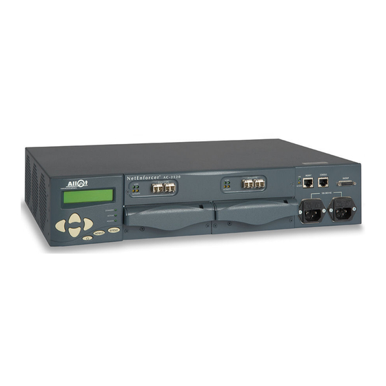
Chapter 1: AC-2500 Series Hardware NetEnforcer Front Panel The AC-2500 series connects to your network via Link Connection connectors. The LCD panel, connectors and LED indicators on the front panel, are shown in the following diagrams. The front panel of each AC-2500 series unit is separated into four areas as shown below: Figure 1-1 –... -
Page 16: Ac-2500 Series Front Panels
Chapter 1: AC-2500 Series Hardware AC-2500 Series Front Panels AC-2520 Front Panels Figure 1-2 – Front Panel: AC-2520 Copper Figure 1-3 – Front Panel: AC-2520 Fiber NetEnforcer AC-2500 Hardware Guide... -
Page 17: Figure 1-4 - Front Panel: Ac-2540 Fiber
Chapter 1: AC-2500 Series Hardware AC-2540 Front Panels Figure 1-4 – Front Panel: AC-2540 Fiber CAUTION CLASS 1 LASER PRODUCT. DANGER! Invisible laser radiation when opened. AVOID DIRECT EXPOSURE TO BEAM. NetEnforcer AC-2500 Hardware Guide... -
Page 18: Lcd Panel
Chapter 1: AC-2500 Series Hardware LCD Panel The NetEnforcer LCD panel provides an indication of traffic usage and enables you to configure NetEnforcer directly without the need to connect a terminal. You can also start, reboot and shutdown NetEnforcer from the front panel. Display Area Display Area Standby Indicator... - Page 19 Chapter 1: AC-2500 Series Hardware Unit Status Indicators The modes of operation of the Standby, Active and Power LEDs on the LCD panel are described in the table below. Indicator Status NetEnforcer Status Standby Two NetEnforcers are connected in Parallel Redundancy mode and this NetEnforcer is the secondary system.
-
Page 20: Power Supply Modules
Chapter 1: AC-2500 Series Hardware Interface Status Indicators The modes of operation of the Link (External and Internal) LEDs are described in the table below. Link Status Indicators Ext/Int LED NetEnforcer Status A lit green LED indicates that a link is detected. Green A blinking red LED indicates that traffic is detected on the interface. - Page 21 Chapter 1: AC-2500 Series Hardware Each power supply has two LEDs located beneath the power supply handles. Model Copper/Fiber options Power inlet options AC-2520 Transceiver SFP Copper AC/DC Transceiver SFP SX Transceiver SFP LX 5 Transceiver SFP LX 20 Transceiver SFP ZX AC- 2540 Transceiver SFP Copper AC/DC...
-
Page 22: Accessories Area
Chapter 1: AC-2500 Series Hardware Accessories Area Management Port (Out of Band Management) Out-of-band management provides the following: • Offers physical separation between shaped traffic and management traffic. • Enables access to NetEnforcer even if there is a problem in the network (for example, DoS attack). - Page 23 Chapter 1: AC-2500 Series Hardware Management Port Status Indicators Management Port Status Indicators – AC-2500 Series The modes of operation of the Management port LEDs are described in the table below. Mgmnt LED NetEnforcer Status Green A lit green LED indicates that a link is detected. Orange A blinking red LED indicates that traffic is detected on the interface.
-
Page 24: Cabling
Chapter 1: AC-2500 Series Hardware Cabling AC-2500 Series Copper NOTE Ethernet Cables may be Straight or Cross, depending upon your network. For those Ethernet cables which are included with the NetEnforcer, see Unpacking the NetEnforcer on p. 1-2 for type details. Shielded cables must be used in order to insure compliance. -
Page 25: Ac-2500 Multi Mode (Sx) Fiber
Chapter 1: AC-2500 Series Hardware AC-2500 Multi Mode (SX) Fiber NOTE Ethernet Cables may be Straight or Cross, depending upon your network. For those Ethernet cables which are included with the NetEnforcer, see Unpacking the NetEnforcer on p. 1-2 for type details. Connections Cable Type Connector Type... -
Page 26: Ac-2500 Series Single Mode (Lx5, Lx20, Zx) Fiber
Chapter 1: AC-2500 Series Hardware AC-2500 Series Single Mode (LX5, LX20, ZX) Fiber NOTE Ethernet Cables may be Straight or Cross, depending upon your network. For those Ethernet cables which are included with the NetEnforcer, see Unpacking the NetEnforcer on p. 1-2 for type details. Connections Cable Type Connector Type... -
Page 27: Connectors
Chapter 1: AC-2500 Series Hardware Connectors NetEnforcer Bypass Units using Multi Mode fiber (SX) utilize dual SC Connectors. Figure 1-6 – Dual SC Connector (Multi Mode Fiber) NetEnforcer Bypass Units using Single Mode fiber (LX5, LX20 and ZX) utilize dual LC connectors. -
Page 28: Bypass Units
Chapter 1: AC-2500 Series Hardware Bypass Units The AC-2500 series operates with an external Bypass Unit. The Bypass Unit is a mission-critical subsystem designed to ensure network connectivity at all times. The Bypass mechanism provides "connectivity insurance" in the event of a NetEnforcer subsystems failure. -
Page 29: Figure 1-8 - Connecting The Netenforcer Ac-2520 To Double Copper Bypass Unit
Chapter 1: AC-2500 Series Hardware The following procedure describes how to connect a Double Copper Bypass Unit to NetEnforcer AC-2520. To External To Internal To External To Internal Router Switch Router Switch Figure 1-8 – Connecting the NetEnforcer AC-2520 to Double Copper Bypass Unit To connect the Double Copper Bypass to the NetEnforcer: NOTE For important information regarding cable and connector types, see... -
Page 30: Figure 1-9 - Double Fiber Bypass Unit - Multimode
Chapter 1: AC-2500 Series Hardware Connect the Internal cable from the Internal port on the Bypass Unit, to a switch connector. Repeats Steps 1 to 4 for Link 2. Connect the D-type High Density connector from the Primary port on the Bypass Unit, to the Backup port on NetEnforcer. -
Page 31: Figure 1-10 - Double Fiber Bypass Unit - Single Mode
Chapter 1: AC-2500 Series Hardware Figure 1-10 – Double Fiber Bypass Unit – Single Mode NOTE Use 62.5/125μ or 9/125μ fiber optic cables with dual LC connectors (not provided) to connect 1 Gbps ports of the switch and the router. The Double Fiber Bypass Unit includes connectors for connecting to Link 1 and Link 2 on the AC-2520. -
Page 32: Figure 1-11 - Connecting The Netenforcer Ac-2520 To Double Fiber Bypass Unit - Single Mode
Chapter 1: AC-2500 Series Hardware The following procedure describes how to connect a Double Fiber Bypass Unit to NetEnforcer AC-2520. To Internal To External Switch Router To External To Internal Switch Router Figure 1-11 – Connecting the NetEnforcer AC-2520 to Double Fiber Bypass Unit – Single Mode To connect the Double Fiber Bypass to the NetEnforcer: NOTE... -
Page 33: Ac-2540 Bypass Unit
Chapter 1: AC-2500 Series Hardware Connect a 62.5/125μ or 9/125μ Internal fiber optic cable from the Internal port on the Bypass Unit to a 1 Gbps switch. Repeats Steps 1 to 4 for Link 2. Connect the D-type High Density connector from the Primary port on the Bypass Unit, to the Backup port on the Primary NetEnforcer. -
Page 34: Figure 1-13 - Connecting The Netenforcer Ac-2540 To Multi-Port Fiber Bypass Unit
Chapter 1: AC-2500 Series Hardware Figure 1-13 – Connecting the NetEnforcer AC-2540 to Multi-Port Fiber Bypass Unit To connect the Bypass Unit to the NetEnforcer AC-2540: NOTE For important information regarding cable and connector types, see Cabling on p. 1-12. 1-22 NetEnforcer AC-2500 Hardware Guide... -
Page 35: Powering Up
Chapter 1: AC-2500 Series Hardware Connect the External cable from the To NetEnforcer External port (Link 1) on the Bypass Unit to the External port on NetEnforcer (Link 1). Connect the Internal cable from the To NetEnforcer Internal port (Link 1) on the Bypass Unit to the Internal port on NetEnforcer (Link 1). -
Page 36: Connection To Dc Power
Chapter 1: AC-2500 Series Hardware When connecting NetEnforcer to 120 / 240 VAC supply, plug into 10 A service receptacles, type N5/10 or NEMA 5-10R. Ensure that each site has a suitable ground. Ground all metal racks, enclosures, boxes and raceways. The NetEnforcer equipment should be reliably grounded through the power supply cord. -
Page 37: Grounding
Chapter 1: AC-2500 Series Hardware The DC supply source is to be located within the same premises as this equipment. There shall be no switching or disconnecting devices in the grounded circuit conductor between the DC source and the point of connection of the grounding electrode conductor. -
Page 38: Powering Up Via Lcd Panel
Chapter 1: AC-2500 Series Hardware Powering Up Via LCD Panel NOTE The NetEnforcer and the Bypass Unit have to be fully plugged and connected before power is turned on. This is to ensure proper and systematic power up. It is recommended to connect the two power line feeds to separate power sources to have full power redundancy. -
Page 39: Chapter 2: Placement In The Network
Chapter 2: Placement in the Network The NetEnforcer is normally placed on the internal side of your access router. The Internal port of the NetEnforcer interfaces with your Local Area Network (LAN) and the External port of the NetEnforcer interfaces with your access router. To connect NetEnforcer to your network: Connect the Bypass Unit to NetEnforcer, as described in Bypass Units, page 1-16. -
Page 41: Chapter 3: Setting Up The Netenforcer
Chapter 3: Setting Up the NetEnforcer In order to manage and configure NetEnforcer policies remotely from your Web browser or NetXplorer centralized management software, several basic parameters must be configured on NetEnforcer. You can configure these basic parameters using a terminal connected to NetEnforcer or by using the LCD panel. -
Page 42: Figure 3-1 - Netenforcer Setup Menu
(see above). The system boots up and you are prompted for a login and a password. 4. Enter admin for the login and allot for the password. (To change the password, see page 3-8.) 5. Press <Enter>. The NetEnforcer Setup Menu is displayed: Figure 3-1 –... - Page 43 Telnet (IP address of NetEnforcer). Press <Enter>. The system boots up and you are prompted for a login and a password. 2. Enter admin for the login and allot for the password. (To change the password, see page 3-8.) Press <Enter>. The NetEnforcer Setup Menu is displayed:...
-
Page 44: Figure 3-2 - Current Configuration (1)
Chapter 3: Setting Up the NetEnforcer Displaying the Current Configuration You can display and view the currently set network configuration parameters at any time. To display the current configuration: In the NetEnforcer Setup Menu, enter 1 (List current configuration) and press <Enter>. -
Page 45: Figure 3-3 - Network Configuration
Chapter 3: Setting Up the NetEnforcer Press <Enter> to return to the NetEnforcer Setup Menu. Configuring Network Parameters You can define network parameters manually. To define network parameters manually: In the NetEnforcer Setup Menu, enter 2 (Network configuration) and press <Enter>. The Network Configuration menu is displayed: Figure 3-3 –... - Page 46 Jonny2. Domain name A domain name for your NetEnforcer, for example, allot.com. Do not provide a leading ‘.’. Default gateway IP address The IP address of your default gateway, for example, 10.0.0.2. If you do not have a default gateway, enter NONE.
- Page 47 Chapter 3: Setting Up the NetEnforcer • The duplex type for the External interface. Enter full for full duplex, half for half duplex or auto for AutoSensing. • If you selected full or half duplex, enter the link speed of the External interface, 10M or 100M.
-
Page 48: Figure 3-4 - Password
You can change the login password for either the Admin user or the Monitor user. The Admin user has access to all NetEnforcer functions, while the Monitor user has read-only access. It is strongly recommended to change the default password (allot). NetEnforcer might enable access from anywhere on the Internet, and should therefore be protected with a unique password. -
Page 49: Figure 3-5 - Time Setup
Chapter 3: Setting Up the NetEnforcer Modifying Date and Time Settings You can modify date and time settings as required. You can set the system time manually, or you can set up NetEnforcer to receive time checks from an NTP (Network Time Protocol) server, if you have one on your network. - Page 50 Chapter 3: Setting Up the NetEnforcer • Press <Enter> to set the time. Changing the Root User Password You can change the root password that provides access to super-user rights. To change the root password: 1. Use the supplied serial cable to connect the terminal to the Console Connector on the front panel of NetEnforcer.
-
Page 51: Configuring Via The Lcd Panel
Chapter 3: Setting Up the NetEnforcer Configuring Via the LCD Panel All NetEnforcer models provide an LCD panel from which you can configure basic NetEnforcer parameters without connecting a terminal. This enables quick and easy setting of basic parameters such as the IP address of NetEnforcer and NIC settings. When not being used to configure the NetEnforcer, the display area in the LCD panel displays its default view, which is the current inbound and outbound bandwidth usage. - Page 52 Chapter 3: Setting Up the NetEnforcer NOTE If QoS functionality is not included in your NetEnforcer (not enabled by your activation key), the default view indicates the following: Inbound:- Outbound:-. Configuring NIC Settings Configuring NIC settings enables you to configure the internal and external Ethernet adapters to either automatically sense the direction and speed of network traffic, or use a predetermined duplex type and speed.
- Page 53 Chapter 3: Setting Up the NetEnforcer [100]/[10] Mbps Use the arrow buttons to select the link speed of the selected interface and press the Enter button. The display area indicates the following: [S]ave/[C]ancel Use the arrow buttons to select whether to save the settings or cancel and press the Enter button.
- Page 54 Chapter 3: Setting Up the NetEnforcer Select whether you have a gateway defined in your network. If you select N then you will exit to the next step, skipping step 2-4. If you have a gateway select Y and proceed: 2-4.Gateway: xxx.xxx.xxx.xxx (the current gateway definitions are displayed) Specify the IP address of the default gateway.
- Page 55 Chapter 3: Setting Up the NetEnforcer Activating Bypass To send the NetEnforcer into Bypass: With the display area displaying the default view, press the Select button. The Main menu is displayed. Press the down arrow three times to display the following: Main menu: 4.
- Page 56 Chapter 3: Setting Up the NetEnforcer Use the arrow buttons to select whether to reboot NetEnforcer and press the Enter button. NetEnforcer reboots and the display area indicates the following: System Rebooting * (blinking asterisk) NOTE This message also appears in the display area when the NetEnforcer is rebooted using a terminal.
- Page 57 Chapter 3: Setting Up the NetEnforcer To return to LCD default view: With the display area displaying the default view, press the Select button. The Main menu is displayed. Press the down arrow six times to display the following: Main menu: 7.
-
Page 59: Chapter 4: Redundancy
Chapter 4: Redundancy Enabling Redundancy Failure of a network device can be catastrophic, causing network downtime and lost business. The key to designing any mission-critical network is to recognize that these failures can occur, and to design a network that can handle failures and still allow the network to function. - Page 60 Chapter 4: Redundancy • Options are: o internal1 MODE:SPEED o internal2 MODE:SPEED o external1 MODE:SPEED o external2 MODE:SPEED For example: go config nic –internal1 full:100 To set redundancy mode: go config network -redund_mode • Options are: o parallel o active o serial For example: go config network –redund_mode parallel To toggle redundancy:...
-
Page 61: Figure 4-1 - Nic Tab Ac-2520 - Netxplorer Configuration
Chapter 4: Redundancy Configuring the AC-2520 via NetXplorer Log into NetXplorer Right click the NetEnforcer you wish to configure in the Navigation Pane Select Configuration from the drop down menu. Open the NIC tab and in the Action on Failure field, set INTERNAL1 and EXTERNAL1 to fail paired port. -
Page 62: Figure 4-2 - Networking Tab Ac-2520 - Netxplorer Configuration
Chapter 4: Redundancy Open the Networking tab and set the Redundancy Mode as required to Parallel, Serial or Active. Select the Enable Bypass Unit checkbox. Figure 4-2 – Networking Tab AC-2520 – NetXplorer Configuration Click Save. The system will reboot After rebooting, you can view the changes from the Configuration tab. - Page 63 Chapter 4: Redundancy 2. Open the NetXplorer GUI by clicking on the icon found on the desktop or from the Start menu. If no icon is installed, browse to the IP of the server. 3. From the GUI, select the relevant NetEnforcer. Right-click and select Configuration.
- Page 64 Chapter 4: Redundancy To set redundancy mode: go config network -redund_mode • Options are: o parallel o active o serial For example: go config network –redund_mode parallel To toggle redundancy: go config network –bypass_unit • Options are: o enable o disable For example: go config network –bypass_unit enable Configuring the AC-2540 via NetXplorer Log into NetXplorer...
-
Page 65: Figure 4-3 - Nic Tab Ac-2540 - Netxplorer Configuration
Chapter 4: Redundancy Figure 4-3 – NIC Tab AC-2540 – NetXplorer Configuration Set INTERNAL2, EXTERNAL2, INTERNAL4 and EXTERNAL4 to No Action in the Action on Failure field. Open the Networking tab and set the Redundancy Mode as required, to Parallel, Serial or Active. Select the Enable Bypass Unit checkbox. -
Page 66: Figure 4-4 - Networking Tab Ac-2540 - Netxplorer Configuration
Chapter 4: Redundancy Figure 4-4 – Networking Tab AC-2540 – NetXplorer Configuration Click Save. The system will reboot After rebooting, you can view the changes from the Configuration tab. For more information concerning NetEnforcer configuration via NetXplorer, see the NetXplorer Operation Guide. NetEnforcer AC-2500 Hardware Guide... -
Page 67: Parallel Redundancy
Chapter 4: Redundancy Parallel Redundancy A NetEnforcer can operate in parallel to provide Parallel Redundancy. Parallel Redundancy requires two NetEnforcer systems and, where an external Bypass Unit is used, a single Bypass Unit. The Primary NetEnforcer handles the traffic and the Secondary NetEnforcer is designed to stand by as long as the Primary NetEnforcer is active. -
Page 68: Status Indicators In Parallel Redundancy Mode
Chapter 4: Redundancy Status Indicators in Parallel Redundancy Mode When operating in Parallel Redundancy mode, two NetEnforcer units are connected. During operation, the LED indicators on NetEnforcer give various readings. The LEDs relevant to operations in Parallel Redundancy mode are the Standby, Active and Power LEDs on the NetEnforcer LCD panel. -
Page 69: Secondary Netenforcer Activation
Chapter 4: Redundancy Standby Active Power Analysis Primary Primary NetEnforcer failed or not Unit completed booting. Secondary Secondary NetEnforcer failed or not Unit completed booting. Bypass is activated (in the primary unit and all traffic is going through Bypass. Table 4-1 – LED Conditions: AC-2500 Series, Parallel Redundancy Mode Secondary NetEnforcer Activation When two NetEnforcers are connected in Parallel Redundancy mode, the Secondary NetEnforcer will take control and become the active unit under the following... - Page 70 Chapter 4: Redundancy To connect two AC-2500 Series NetEnforcers in Parallel Redundancy: Before using NetEnforcers in Parallel Redundancy mode, make sure that the configuration of both NetEnforcers is identical; except for their IP addresses, which must be unique for each unit. After ensuring identical configuration, test each NetEnforcer (while connected to the network as a single device) and verify that they are operating identically to one another.
-
Page 71: Active Redundancy
Chapter 4: Redundancy Active Redundancy In an Active Redundancy configuration, each NetEnforcer manages a single link while duplicating the link’s traffic to the other NetEnforcer. Both NetEnforcers are active. Each unit shapes the traffic of one link only, but the shaping algorithm considers traffic of both links. -
Page 72: Connecting The Netenforcer In Active Redundancy
Chapter 4: Redundancy Connecting the NetEnforcer in Active Redundancy Line 1 (and 2 in the AC-2540) is used to pass actual traffic – these interfaces will be used to connect the NetEnforcers to the corresponding switches or routers. Line 3 (and 4 in the AC-2540) is used to duplicate traffic and pass it to the second NetEnforcer. -
Page 73: Serial Redundancy
Chapter 4: Redundancy • The remaining interfaces of the bypass units remain unconnected. Serial Redundancy In Serial Redundancy two bypass units are connected to the network in serial and the two NetEnforcers work in Active/Bypass mode. One NetEnforcer is in active mode at all times, and the other is in bypass mode. There is no NetEnforcer is standby mode. -
Page 74: Netenforcer Failover
Chapter 4: Redundancy NetEnforcer Failover In case the Primary NetEnforcer fails, the unit will go in to bypass mode forwarding all traffic directly to the network bypassing the failed NetEnforcer. The Secondary NetEnforcer will go in to active mode forwarding all traffic via the secondary unit. NetEnforcer functionality will be maintained. -
Page 75: Serial Redundancy In Mesh Topologies
Chapter 4: Redundancy Figure 4-7 – Serial Redundancy – Bypass Scenario Serial Redundancy in Mesh Topologies Serial Redundancy can support mesh topology configurations. In the network diagram described below, each of the NetEnforcer units should be able to handle two links which requires it to have four network interfaces. -
Page 76: Figure 4-8 - Serial Redundancy - Mesh Scenario
Chapter 4: Redundancy Figure 4-8 – Serial Redundancy – Mesh Scenario In a network configuration with four network interfaces, each of the NetEnforcer units must have eight network interfaces. The AC-2540 can be used in such a configuration 4-18 NetEnforcer AC-2500 Hardware Guide... -
Page 77: Chapter 5: Hardware Specifications
Chapter 5: Hardware Specifications Dimensions Standard 2U by 19-inch, rack mountable Height 3.46 in (88 mm) Width 17.32 in (440 mm) Depth 14.76 in (375 mm) Weight Copper: 24.9 lbs (11.3 kg) Fiber: 25.3 lbs (11.48 kg) NOTE The weight of the Copper Bypass Unit is 3.86 lbs (1.75 kg) and the weight of the Fiber Bypass Unit is 4.28 lbs (1.94 kg). -
Page 78: Operating Environment
Chapter 5: Hardware Specifications Operating Environment Temperature 32° F to 104° F (0° to 40° C) Humidity 5% to 95% (non condensing) NetEnforcer AC-2500 Hardware Guide... -
Page 79: Standards, Compliance And Certifications
Chapter 5: Hardware Specifications Standards, Compliance and Certifications EMC Directive 89/336/EEC, article 7(1) EN 55022:1998+A1(00) class A EN 61000-3-2:1995_A1(98)+A2(98) EN 61000-3-3:1995 EN 55024:1998+A1(01) FCC 47 CFR part 15, subpart B, class A ICES-003:1997, class A VCCI:2002, class B NEBS: GR-1089-Core* Safety IEC 60950:1999 with Japanese deviations EN 60950:2000... -
Page 81: Chapter 6: Firewall Port Reference
Chapter 6: Firewall Port Reference In some networks, the NetEnforcer can be separated from the NetXplorer server by a firewall for security reasons. To enable the communication between the NetXplorer and NetEnforcers the following ports in the Firewall should be opened: •... -
Page 83: Chapter 7: Équipement De Série Ac-2500
Chapter 7: Équipement de série AC-2500 Le NetEnforcer est une passerelle d’apprentissage transparente certifiée conforme à la norme IEEE 802.1, fonctionnant parallèlement à une unité de dérivation en vue d’assurer la continuité du débit de données en cas de problème matériel ou logiciel. La dérivation du NetEnforcer redirige l’ensemble du trafic uniquement vers des éléments passifs, permettant ainsi au réseau de fonctionner. -
Page 84: Mises En Garde D'ordre Général
Chapter 7: Équipement de série AC-2500 Mises en garde d’ordre général CONFIGURATION Afin de garantir une continuité de service en cas de panne, l’ensemble des modèles de la série AC-2500 fonctionne uniquement en raccordement avec une unité de dérivation adaptée. LASER PRODUIT LASER DE CLASSE 1. - Page 85 Chapter 7: Équipement de série AC-2500 pas être contrecarrée par l’utilisation d’une rallonge non munie d’un conducteur de protection (relié à la masse). Toute interruption du conducteur de protection (relié à la masse) ou toute déconnection de la borne de masse de protection pourrait compromettre la sécurité...
-
Page 86: Remarques D'ordre Général
Chapter 7: Équipement de série AC-2500 Remarques d’ordre général LASER Dans le cas d’un produit doté d’un émetteur-récepteur en fibre optique, les émissions dégagées par les produits décrits dans ce guide sont de Catégorie 1, conformément aux normes IEC 60825-1 et FDA 21 CFR 1040.10 / 1040.1. Ces produits ne doivent en aucun cas être installés dans un réseau optique traitant des émissions de classe supérieure à... -
Page 87: Spécifications Matérielles
Chapter 7: Équipement de série AC-2500 Spécifications matérielles Dimensions Conception 2U standard de 19 pouces, montable en rack Hauteur 88 mm (3.46 in.) Largeur 440 mm (17.32 in.) Profondeur 375 mm (14.76 in.) Poids Cuivre: 11,3 kg (24.9 lbs) Fibre optique: 11,48 kg (25.3 lbs) REMARQUE L’unité...
Need help?
Do you have a question about the NetEnforcer AC-2500 Series and is the answer not in the manual?
Questions and answers