Advertisement
Quick Links
Description and Operation
Description and Operation
Description and Operation
Description and Operation
Description and Operation
Edwards Tone Generator and Speaker/Amplifiers are
intended for industrial applications where high audible
output and microcomputer reliability are required.
Catalog Series 5532M ending with suffixes -AQ, -24AQ,
-Y6 or -24Y6 are CE Marked. Additionally, the Adaptatone
Millennium series are UL and cUL Listed as Audible Signal
Appliances for use in the following hazardous locations.
Catalog
Number
5532M-AQ
Class I, Div. 2, Groups A, B, C, D
5532M-N5
Class II, Div. 2, Groups F, G
5532M-Y6
Class III, Div. 1 and 2
5532MHV-AQ
5532MHV-Y6
5540M-485Y6
Class I, Div. 2, Groups A, B, C, D
5540MV-485Y6
Class II, Div. 2, Groups F, G
Class III, Div. 1 and 2
The 5532B Speaker/Amplifiers are UL Listed and CSA Cer-
tified as Audible Signaling Appliances.
The 5532M-Y6 is additionally UL Listed in a Speaker and
Amplifier category, when powered with 120V/240V AC
50/60 Hz, for use in conjunction with the 5541M-Y6 Mil-
lennium System Master either for emergency/evacuation,
non-fire, or for supplementary fire alarm control panel
accessory applications (see Instructions for 5541M-Y6,
part 3100471).
The Tone Generator operates from local power. It accom-
modates up to four normally-open contacts on its inputs.
The tone that sounds in response to an active input is
determined by setting miniature programming switches
inside the unit. Figure 19 has switch settings for setting
tones.
Four tones may be programmed into the Tone Generator
at any time. These tones operate on a pyramid-type pri-
ority system. The tone programmed on SW1 overrides
the tones programmed on SW2, SW3, and SW4. The tone
on SW2 overrides the tones programmed on SW3 and SW4.
Likewise, the tone on SW3 overrides the tone programmed
on SW4. The tone programmed on SW4 has the lowest
priority and cannot override any other programmed tone.
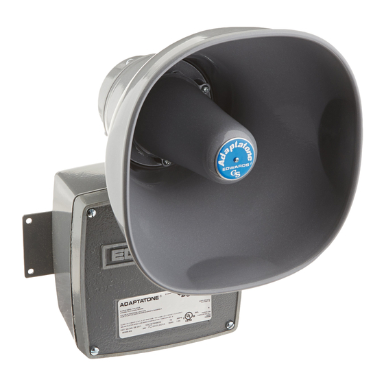
Speaker/Amplifiers are heavy-duty, stand-alone signaling
devices that operate from local power and sound a tone
programmed at the Tone Generator. Speaker direction
and the output level are easily adjustable.
Specifications
Specifications
Specifications
Specifications
Specifications
Weight - Tone Generator ....................... 6 Pounds (2.7 kg)
Weight - Speaker/Amplifier .................. 9 Pounds (4.1 kg)
Hazardous Locations, UL Standard UL1604
Ambient Temp. ................... +41F to +104F (+5C to +40C)
Non-Hazardous Locations
Variable Ambient Temp. ..... -40F to +151F (-40C to +66C)
Hazardous Locations and Variable Ambient Conditions apply only
where UL listings are accepted and do not apply to either CE confor-
mity or TUV-Rheinland Certification.
Installation Instructions for Adaptatone Millennium Tone Generator Series 5540M-485
and Tone Generator with Voice Messaging Series 5540MV-485 and
Hazardous
Locations
Speaker/Amplifier, Series 5532
Electrical Specifications
Electrical Specifications
Electrical Specifications
Electrical Specifications
Electrical Specifications
Catalog
Number
Tone Generator
5540M-485Y6
5540MV-485Y6
Temp.
Speaker/Amplifier - Standard Volume
Code
5532M-AQ
T4 (135C)
T5 (100C)
5532M-N5
5532M-Y6
T4 (135C)
T5 (100C)
5532B-AQ
5532B-N5
5532B-Y6
Speaker/Amplifer - High Volume
5532MHV-AQ
5532MHV-Y6
5532BHV-AQ
5532BHV-Y6
*5532M-Y6 is suitable for use with 120/240V AC Main Power input in conjunction
with the 5541M-Y6 Millennium System Master either for emergency/evacuation,
non-fire, or for supplementary fire alarm control panel accessory applications (see
instructions for 5541M-Y6, part 3100471).
Input Board
Voltage Current
Voltage
24V DC
6 mA
125V DC**
250V DC**
120V AC 50/60 Hz
240V AC 50/60 Hz
24V DC
24V AC 50/60 Hz
120V AC 50/60 Hz
125V DC**
250V DC**
120V AC 50/60 Hz
240V AC 50/60 Hz
24V DC
36V DC
24V AC 60 Hz
24V AC 50 Hz
120V AC 60 Hz
120V AC 50 Hz
125V DC**
250V DC**
120V AC 60 Hz
240V AC 60 Hz
120V AC 50 Hz
240V AC 50 Hz
24V DC
24V AC 50/60 Hz
125V DC
250V DC
120V AC 50/60 Hz
240V AC 50/60 Hz
24V DC
36V DC
24V AC 60 Hz
24V AC 50 Hz
125V DC
250V DC
120V AC 60 Hz
240V AC 60 Hz
120V AC 50 Hz
240V AC 50 Hz
P/N 3100346 ISSUE 3 © 2003
Main Power
Current (A)
Standby Tone On
0.10
0.21
0.02
0.10
0.10
0.32
0.10
0.20
0.10
0.74
0.10
1.3
0.10
0.36
0.10
0.21
0.02
0.10
0.10
0.32
0.10
0.20
0.06
0.69
0.07
0.84
0.26
1.36
0.26
1.36
0.10
0.29
0.09
0.29
0.05
0.16
0.04
0.10
0.10
0.29
0.11
0.23
0.09
0.29
0.10
0.22
0.10
1.5
0.10
2.3
0.10
0.39
0.02
0.19
0.10
0.56
0.10
0.34
0.06
1.51
0.07
1.98
0.26
1.86
0.26
1.86
0.05
0.25
0.04
0.23
0.10
0.62
0.11
0.33
0.09
0.62
0.10
0.33
Advertisement

Related Manuals for Edwards Signaling 5540M-485 Series

Summary of Contents for Edwards Signaling 5540M-485 Series
- Page 1 Installation Instructions for Adaptatone Millennium Tone Generator Series 5540M-485 and Tone Generator with Voice Messaging Series 5540MV-485 and Speaker/Amplifier, Series 5532 Description and Operation Description and Operation Description and Operation Electrical Specifications Electrical Specifications Electrical Specifications Electrical Specifications Electrical Specifications Description and Operation Description and Operation Input Board...
- Page 2 Dimensions 5532M 5532MHV 8 7/8" 11 1/2" (225 mm) (292 mm) 8 1/4" 9 3/4" (210 mm) (248 mm) 13" 14 1/4" (330 mm) (362 mm) Figure 1. Speaker/Amplifier Dimensions PROGRAMMING DIPSWITCH TERMINAL BLOCK TB1 INPUT BOARD (SEE FIGURE 7) PROGRAMMING DIPSWITCH (SWITCHES SHOWN...
-
Page 3: Flat Surface Mounting
d. Connect incoming power to wire leads using a CAUTION CAUTION CAUTION CAUTION CAUTION butt splice or other method listed, certified, or otherwise approved by local authorities. Leads During installation, care must be taken so that components are black and white. on the printed circuit board are not damaged. - Page 4 terminals 3 and 4 on the main board of the tone W A R N I N G S W A R N I N G S W A R N I N G S W A R N I N G S W A R N I N G S generator per Figure 7.
- Page 5 Table 2.2 Unit Address Switch Configuration (Cont'd) Unit Address S1-1 S1-2 S1-3 S1-4 S1-5 Decimal OPEN OPEN OPEN OPEN CLOSED CLOSED OPEN OPEN OPEN CLOSED OPEN CLOSED OPEN OPEN CLOSED CLOSED CLOSED OPEN OPEN CLOSED OPEN OPEN CLOSED OPEN CLOSED CLOSED OPEN CLOSED...
- Page 6 <ZONE> Programmable unit Zone issued by the master or controlling computer Range ASCII A-D (1 byte). Note – Zone value is not retained after power loss unless battery backup is installed. Value defaults to Zone A on power up. <ETX> The <ETX>...
- Page 7 <00> Two byte ASCII ‘00’ used as protocol padding (two byes) <ZONE> Programmable unit zone character. Range ASCII A-D. (1byte) <ETX> The <ETX> character has a value of 3 hexadecimal and is required at the end of every message (1 byte) <CHKSUM>...
- Page 8 <CHKSUM> Optional two byte Message Block checksum (2 bytes). Refer to Section 4.0 for Block checksum calculation and verification. If checksum is not desired, must pad these two bytes with two ASCII zeros 00. Unit Response: <STX><UA> 44 <TIME LEFT><ACK><ETX> <CHKSUM> <UA>...
- Page 9 <CHKSUM> Receiving unit calculates two-byte checksum and returns ASCII value. Refer to Section 4.0 for Block checksum calculation and verification. Example: Command: <STX>014500A<ETX>00 Response: <STX>01M-485v1.0<ETX>84 Unit address 01 returns “M-485” string and is configured with version 1, rev.0 firmware. Calculated two-byte checksum is ‘84’. RELAY ENERGIZE COMMAND - 31 Send Format: <STX><UA>31<TIME>...
- Page 10 <30> Two byte ASCII Command 30 echoed back from receiving unit. <00> Two byte ASCII ‘00’ used as protocol padding (two byes) <ACK> Unit received valid message and checksum <ETX> The <ETX> character has a value of 3 hexadecimal and is required at the end of every message (1 byte).
- Page 11 The calculated Message Block checksum are appended to the message string. Two bytes, ASCII 7 and ASCII 1, consume these two checksum data fields. See below. Send format: <STX>054300A<ETX>71 Wiring applications RS-232 to RS-485 Multi or Single drop RS-232 Port RS-485 cable DB9 F/M (up to 4000 ft)
- Page 12 RS-485 Multi or Point to Point RS-485 Port RS-485 cable (up to 4000 ft) Tone Generator 5540M-485Y6 or PLC Controller 5540MV-485Y6 IBM PC with RS485 Serial Port Tone Generator 5540M-485Y6 or 5540MV-485Y6 Up to 32 units (maximum) Suggested Network Topology Node Schemes PAGE 12 P/N 3100346 ISSUE 3...
- Page 13 Wiring to RS-232/485 Convert Box (MCN485CB2EOLT) RJ11 PINOUT 1 2 3 4 5 6 1 = NC 2 = RS-485 (+) RS-485 (+) RS-485 (-) 3 = SHIELD BLACK NOT A 4 = NC SHIELD TELEPHONE 5 = RS-485 (-) CONNECTION 9 VOLT AC 6 = NC...
- Page 14 Power and Signal/Tone leads from 5540 to be earth-ground connected to Audio Coupler Board as Plastic tie-wrap (provided)-- leads--black and applicable. use to separate power leads white or black for from signal and tone initiating leads power; yellow striped green for earth-ground.
- Page 15 RELAY POWER SUPERVISION (WHERE APPLICABLE) AUD + AUD - AUDIO COUPLER BOARD TO OTHER SPEAKER/AMPLIFER AUDIO COUPLER BOARDS TONE GENERATOR Figure 7. Wiring Audio Output of Tone Generator to Speaker/Amplifer Audio Coupler Board INPUT BOARD PROGRAMMING SWITCHES (ON OTHER SIDE) AUDIO INPUT BOARD...
- Page 16 Figure 11. Connecting to the 5532B Series Speaker/Amplifiers PAGE 16 P/N 3100346 ISSUE 3...
- Page 17 Figure 12. Tone Programming Switch Tone Description No Tone Ding-Dong Percussive pairs of 700 and 570 Hz tones, each damped to zero Warble 575 and 770 Hz alternately, 87 ms each Siren 600-1250 Hz up and down sweep in 8 seconds and repeat Stutter Percussive 470 Hz, 83 ms on, 109 ms off Slow Whoop...
-
Page 18: Description And Operation
Installation Instructions for Adaptatone Millennium Tone Generator Series 5540M-24, 5540M-120 and Tone Generator with Voice Messaging Series 5540MV-24 and Speaker/Amplifier, Series 5532 Description and Operation Electrical Specifications Input Board Main Power Catalog Current (A) Number Voltage Current Voltage Standby Tone On Tone Generator 5540M-24AQ 24V DC... - Page 19 Dimensions 5532M 5532MHV 8 7/8" 11 1/2" (225 mm) (292 mm) 8 1/4" 9 3/4" (210 mm) (248 mm) 13" 14 1/4" (330 mm) (362 mm) Operating voltage Max. off state Continuous on current Surge (inrush/duration) Cat. No. (Volts*) leakage current (mA) (mA) (Amps/milliseconds) 5540M-24AQ...
-
Page 20: Installation
Installation WARNING NOTE: The increased resistance due to long wire runs needs to be accounted for in sizing wire. Consult Applications Engineering for details. CAUTION .lat Surface Mounting Rigid Pipe Mounting NOTE: Cover screws are captive. Do not remove from cover. -
Page 21: Maintenance And Test
WARNING WARNING NOTE: Terminal block TB1 can be unplugged from the main board of the tone generator to complete wiring. Maintenance and Test WARNING WARNING PAGE 4 P/N 3100010 ISSUE 3... - Page 22 Audio output wiring to be connected to Audio Coupler Board of 5532M. Double wire, shielded cable with braid or drain connected to earth-ground lead of 5540. Up to 2500 5532M Series can be so connected in parallel to a single 5540M Series unit. Signal/Tone initiating leads to be Power and Power and...
- Page 23 INPUT ON INPUT BOARD BOARD (5V DC to 24V DC +/- 1%) FROM CUSTOMER CIRCUIT CUSTOMER CIRCUIT INPUT BOARD NEUTRAL LINE 120V AC ON INPUT BOARD RELAY POWER SUPERVISION (WHERE APPLICABLE) AUD + AUD - AUDIO COUPLER BOARD TO OTHER SPEAKER/AMPLIFER AUDIO COUPLER BOARDS TONE GENERATOR...
- Page 24 INPUT BOARD PROGRAMMING SWITCHES (ON OTHER SIDE) AUDIO INPUT BOARD MAIN BOARD MAIN BOARD DIRECTION OF DIRECTION OF INCREASING INCREASING VOLUME VOLUME POTENTIOMETER FOR PROCESSOR BOARD POTENTIOMETER FOR VOLUME ADJUSTMENT VOLUME ADJUSTMENT INPUT BOARD (TONE GENERATOR ONLY) PROGRAMMING SWITCHES (ON OTHER SIDE) VOICE BOARD MAIN BOARD DIRECTION OF...
- Page 25 ON INPUT BOARD VAC 1 L1 120V AC (AC-HOT) OUT 0 OUT 1 OUT 2 OUT 3 VAC 2 OUT 1 OUT 2 OUT 3 OUT 4 OUT 5 OUT 6 OUT 7 TO PLC AC COM PAGE 8 P/N 3100010 ISSUE 3...
- Page 26 Switch Tone Description .or Evacuation Use Only .or Evacuation Use Only Evacuation Use Only .or Evacuation Use Only CAUTION P/N 3100010 ISSUE 3 PAGE 9...
Need help?
Do you have a question about the 5540M-485 Series and is the answer not in the manual?
Questions and answers