Table of Contents

Summary of Contents for Paradox Digiplex Evo APR-PRT3
- Page 1 APR-PRT3 Printer Module: ASCII Protocol Programming Instructions We hope this product performs to your complete satisfaction. Should you have any questions or comments, please visit www.paradox.com and send us your comments.
-
Page 2: Table Of Contents
Table of Contents Technical Specifications ..........1 Request User Label ..........13 Installation ..............2 Area Arm ..............13 Overview ..............2 Area Quick Arm ............13 Programming Sections ..........2 Area Disarm ............. 14 Serial Port Setup ............3 Emergency Panic ............ -
Page 3: Installation
Installation The Printer Module is connected to the control panel’s combus. Connect the four terminals labeled red, black, green, and yellow of the module to the corresponding terminals on the control panel as shown in Figure 2 on page 21. See the EVO or DGP-848 Reference & Installation Manual for the maximum allowable installation distance from the control panel. -
Page 4: Serial Port Setup
ASCII Protocol, set options [5] and [6] to OFF . = default setting For more information on the Clipsal C-Bus Protocol, see the C-Bus Programming Instructions on our website at paradox.com. Virtual Input Programming The home automation module can be programmed to open/close the Printer Module’s virtual inputs and generate activity within the Digiplex system. - Page 5 Section Data Description Default [701] __/__/__ (000 to 255) x Base Time Virtual Input 1 Timer Refer to the table below for a list of the programming sections for all virtual inputs. Virtual Virtual Virtual Virtual Section Section Section Section Input Input Input...
- Page 6 [780] close command virtual input timer close command or virtual input timer [790] close command virtual input timer close command or virtual input timer [800] close command virtual input timer close command or virtual input timer [810] close command virtual input timer close command or virtual input timer [820] close command...
-
Page 7: Virtual Pgm Programming
Virtual PGM Programming The Printer Module supports up to 30 virtual PGMs which are not related to any physical output on the module, but operate in the same manner and are programmed in the same way as traditional PGMs. The tables below offer an example of the virtual PGM programming sections which must be set for virtual PGM 1. - Page 8 = default setting Virtual Section [1] OFF / [2] OFF [1] ON / [2] OFF [1] OFF / [2] ON [1] ON / [2] ON [100] no deactivation deactivation event virtual PGM timer deactivation event or virtual PGM timer [110] no deactivation deactivation event virtual PGM timer...
- Page 9 [201] __/__/__ (000 to 255) x Base time [351] __/__/__ (000 to 255) x Base time [211] __/__/__ (000 to 255) x Base time [361] __/__/__ (000 to 255) x Base time [221] __/__/__ (000 to 255) x Base time [371] __/__/__ (000 to 255) x Base time [231]...
- Page 10 [230] message not resent message resent [380] message not resent message resent [240] message not resent message resent [390] message not resent message resent Sections [102] to [105] Virtual PGM Activation Event The Virtual PGM Activation Event determines which event will activate the Printer Module’s virtual PGM output(s). The Event Group specifies the event, the Feature Group identifies the source, and the Start # and End # set the range within the Feature Group.
- Page 11 Enter the sections that correspond to the Event Group, Feature Group, Start # and End # of the PGM. Event Group Feature Group Start # End # Section Section Section Section Virtual PGM1 [106] __/__/__ [107] __/__/__ [108] __/__/__ [109] __/__/__ Virtual PGM2 [116]...
-
Page 12: Ascii Protocol
ASCII Protocol The ASCII Protocol is a serial communication protocol which allows your home automation module to communicate with the Digiplex control panel through the APR-PRT3 Printer Module. The home automation module must be programmed with the ASCII Protocol in order for successful communication to occur. -
Page 13: Request Area Status
Request Area Status The following commands request the area status. Areas 05-08 only apply when using an EVO96 / EVO192 control panel. Byte 1 Byte 2 Byte 3 Byte 4 Byte 5 Byte 6 <cr> Request Area Status 01 <cr> Request Area Status 02 <cr>... -
Page 14: Request Area Label
The Request Zone Label command also involves an information request. When the command is valid, the first five characters of the command are returned followed by the requested zone label. All zone labels are 16 characters in length. Request Area Label The following commands request the area label. -
Page 15: Area Disarm
A (Regular arm) F (Force arm) <cr> Quick Arm Area 02 S (stay arm) I (Instant arm A (Regular arm) <cr> Quick Arm Area 08 F (Force arm) S (stay arm) I (Instant arm The One-Touch feature must be enabled in the Digiplex control panel to use this feature. See the appropriate Digiplex control panel’s Reference and Installation Manual for more information. -
Page 16: Fire Panic
Fire Panic The following commands are used for fire panic alarms in up to eight areas. Areas 05-08 only apply when using an EVO96 / EVO192 control panel. Byte 1 Byte 2 Byte 3 Byte 4 Byte 5 Byte 6 Panic 3 - Fire Area 01 <cr>... -
Page 17: System Events
System Events All Digiplex system events are sent through the Printer Module to the home automation module using the following format. Byte 1 Bytes 2-4 Byte 5 Bytes 6-8 Byte 9 Bytes 10-12 xxx* yyy** zzz*** System Event * xxx represents the 3-digit event group (G). ** yyy represents the 3-digit event number (N). - Page 18 Event Event Group Description Event Number (N) Event Number Description Area Number (A) Group (G) Auto Arming Arming by WinLoad Late to Close No Movement Arming Special Arming Partial Arming 001-008 One-touch Arming Future Use Future Use (InTouch) Voice Module Arming Disarm with Master 001-999 User Codes...
- Page 19 Event Event Group Description Event Number (N) Event Number Description Area Number (A) Group (G) Zone Tamper Restore 0-096 Zone Numbers 001-008 Special Tamper Keypad Lockout 001-008 TLM Trouble AC Failure Battery Failure Auxiliary Current Limit Trouble Event 000-008 Bell Current Limit Bell Absent Clock Trouble Global Fire Loop...
- Page 20 Event Event Group Description Event Number (N) Event Number Description Area Number (A) Group (G) Power up after total power down Software reset (Watchdog) Test Report Future Use Special Events 000-008 WinLoad In (connected) WinLoad Out (disconnected) Installer in programming Installer out of programming Early to Arm by User 001-999...
- Page 21 Event Event Group Description Event Number (N) Event Number Description Area Number (A) Group (G) Intellizone Delay Engaged** Fire Delay Engaged Auto Arm Arming with Voice Module (set until See Note 1 Exit Delay finishes) Status 3 on page 20 Tamper Zone Low Battery Fire Loop Trouble...
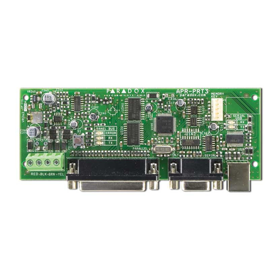
- Page 22 Figure 2: .APR-PRT3 Connection 1) Green “RX” LED: Flashes when the Printer Module is receiving data through the serial port only. 2) Red “TX” LED: Flashes when the Printer Module is transmitting data through the serial port only. 3) 25-Pin Parallel Port: Connect the Printer Module’s 25-pin parallel port to any dot matrix printer. Note: The dot matrix printer must support a minimum of 80 columns.
-
Page 23: Pgm Activation Event
Appendix 1: Programming PGM A PGM is a programmable output that toggles to its opposite state (i.e. a normally open PGM will close) when a specific event occurs in the system. For example, a PGM can be used to reset smoke detectors, activate strobe lights, open/close garage doors and much more. PGM Activation Event The PGM Activation Event determines which event from which source will activate the PGM. - Page 24 Event Event Feature Group Feature Start # End # Group TLM Trouble (see NOTE 3 on page 28) Smoke detector reset Arm with no entry delay Arm in Stay mode Arm in Away mode Full arm when in Stay mode Voice module access Remote control access Non-reportable Event...
- Page 25 Event Event Feature Group Feature Start # End # Group Auto Arming Arming by WinLoad Late to Close No Movement Arming Partial Arming Special Arming One-touch Arming Future Use Future Use (InTouch) Voice Module Arming Any special arming event Not Used Not Used User Codes 001 to 255 001 to 255...
- Page 26 Event Event Feature Group Feature Start # End # Group Auto Arm Cancelled One-touch Stay/Instant Disarm Disarming with WinLoad Disarming with WinLoad after alarm WinLoad cancelled alarm Special Disarm Events Future Use Future Use Future Use (InTouch) Voice Module Disarming Any special disarm event Not Used Not Used...
- Page 27 Event Event Feature Group Feature Start # End # Group TLM Trouble (see NOTE 2 on page 28) AC Failure Battery Failure Auxiliary Current Limit Trouble Event Bell Current Limit Bell Absent Clock Trouble Global Fire Loop Any trouble event Not Used Not Used TLM Trouble...
- Page 28 Event Event Feature Group Feature Start # End # Group Power up after total power down Software reset (Watchdog) Test Report Future Use Special Events WinLoad In (connected) WinLoad Out (disconnected) Installer in programming Installer out of programming Any special event Not Used Not Used User Codes 001 to 255...
- Page 29 Event Event Feature Group Feature Start # End # Group Armed Force Armed Stay Armed Instant Armed See Note 1 Status 1 on page 28 Strobe Alarm Silent Alarm Audible Alarm Fire Alarm Ready Exit Delay Entry Delay System in Trouble See Note 1 Status 2 Alarm in Memory...
- Page 30 Warranty Paradox Security Systems Ltd. (“Seller”) warrants its products to be free from defects in materials and workmanship under normal use for a period of one year. Except as specifically stated herein, all express or implied warranties whatsoever, statutory or otherwise, including without limitation, any implied warranty of merchantability and fitness for a particular purpose, are expressly excluded. Because Seller does not install or connect the products and because the products may be used in conjunction with products not manufactured by Seller, Seller cannot guarantee the performance of the security system and shall not be responsible for circumstances resulting from the product’s inability to operate.
Need help?
Do you have a question about the Digiplex Evo APR-PRT3 and is the answer not in the manual?
Questions and answers